Nomenclature
Symbols
-
 ${C_{bat}}$
-
battery discharge rate (C)
-
$DL$
-
disk loading (
${\rm{N}}/{{\rm{m}}^2}$
) -
${e_{SoC}}$
-
effect of battery SoC
-
$E$
-
energy consumption (
${\rm{kWh}}$
) -
$FM$
-
figure of merit
-
$GW$
-
aircraft’s gross weight (
${\rm{kg}} \cdot {\rm{m}}/{{\rm{s}}^2}$
) -
${H_p}$
-
hybrid power ratio
-
${k_{control}}$
-
control margin to be added when trimming and accelerating
-
${k_{download}}$
-
wing download factor in vertical and transition flight
-
${k_{fuel}}$
-
engineering factor that takes into account the additional fuel tank weight and fuel trapped ratio relative to the weight of loaded fuel
-
${k_{OPI}}$
-
power overhead under a OPI failure mode
-
$ L/D$
-
lift to drag ratio
- N
-
number of components
-
$P$
-
power (
${\rm{kW}}$
) -
$R$
-
ratio
-
$SFC$
-
specific fuel consumption (
${\rm{kg}}/{\rm{kWh}}$
) -
$SoC$
-
battery state of charge
-
$SoH$
-
battery state of health
-
$SP$
-
specific power (
${\rm{kW}}/{\rm{kg}}$
) -
$V$
-
velocity (
${\rm{m}}/{\rm{s}}$
) -
$\varepsilon $
-
constant of voltage drop model by battery SoC
-
$\eta $
-
efficiency
-
$\rho $
-
air density (
${\rm{kg}}/{{\rm{m}}^3}$
) -
${\rm{\Pi }}$
-
normalised power
-
${\theta _{sizing\;point}}$
-
argument of sizing point


Subscripts
-
$VTOL$
-
vertical takeoff and landing flight mode including hover-climb, transition, and descent
-
$cruise$
-
cruise flight mode (airplane mode)
-
$nominal$
-
nominal mission (mission profile excluding reserve)
-
$reserve$
-
reserve
-
$req$
-
required
-
$avail$
-
available
-
$bat$
-
battery
-
$TG$
-
turbo-generator
-
$fuel$
-
aviation fuel
-
$total$
-
battery + TG
-
$HS$
-
hybrid system including TG, battery, and fuel
-
$charge$
-
charging battery
-
$ini$
-
initial
-
$max$
-
maximum
-
$min$
-
minimum
-
$cont$
-
continuous
-
$cont\;to\;max$
-
continuous to maximum
-
$normal$
-
normal flight mode (non-failure mode)
-
$failure$
-
failure mode
-
$OEI$
-
one engine inoperative
-
$OBI$
-
one battery pack inoperative
-
$OPI$
-
one proprotor inoperative
-
$electric$
-
electric component including motor, inverter and thermal management system
-
$prop$
-
propeller
-
$proprotor$
-
proprotor
-
$crit$
-
critical


1.0 Introduction
The electrification trend in aviation is driving the fast-paced advancement of electric vertical takeoff and landing (eVTOL) aircraft [Reference Garrow, German and Leonard11, Reference Geržinič, van Oort, Hoogendoorn-Lanser, Cats and Hoogendoorn12]. Simultaneously, various eVTOL aircraft suitable for urban air mobility (UAM) ecosystems have been proposed, specifically aimed at alleviating traffic congestion in metropolitan areas [Reference Holden and Goel16]. Beyond urban transportation solutions, there is a growing demand for regional air mobility (RAM) aircraft designed for intercity trave [Reference Hader and Baur14]. These aircraft, similar to the eVTOLs used in metropolitan areas, are tailored to efficiently cover longer distances, addressing the need for faster and more sustainable travel between regions. This emerging trend represents a shift in focus from simply alleviating urban congestion to improving regional connectivity. However, battery-powered eVTOL aircraft have limitations for long-range flights beyond a few hundred miles [Reference Adu-Gyamfi and Good1] owing to the low specific energy of currently available batteries [Reference Maheshwari, Mudumba, Sells, DeLaurentis and Crossley21, Reference Rendón, Sánchez, Gallo and Anzai28, Reference Viswanathan, Epstein, Chiang, Takeuchi, Bradley and Langford31, Reference Warren, Garbo, Kotwicz Herniczek, Hamilton and German34]. A gas turbine (GT) hybrid propulsion system is one of solutions for developing a long-range eVTOL aircraft using the current battery technology [Reference Bowman, Felder and Marien2, Reference Salem, Palaia and Quarta29, Reference Ye, Savvarisal, Tsourdos, Zhang and Jason35, Reference Zhang, Saudemont, Robyns and Petit37].
The turbo-generator (TG)—a compact unit integrating a gas turbine with an electrical generator—has undergone continuous engineering advancements to achieve higher power density, improved thermal management, and mechanical reliability [Reference Ginet, Joho and Verrier13]. These developments provide a technological foundation for hybrid-electric propulsion in next-generation aircraft, including eVTOL configurations. Among various hybrid configurations, the series hybrid propulsion system is the most suitable hybrid propulsion system for eVTOL aircraft with distributed electric propulsion because batteries can be charged and discharged during flight [Reference Finger, Braun and Bil7, Reference Rendón, Sánchez, Gallo and Anzai28]]. A hybrid power system that combined a battery pack system with a turbo-generator (TG) component has been studied [Reference Kuśmierek, Galiński and Stalewski18]. Recent studies have used a hybrid power ratio sweep approach [Reference Isikveren, Kaiser, Pornet and Vratny17] to design an aircraft that satisfied these requirements while having an optimal hybrid power system. Hoelzen et al. [Reference Hoelzen, Liu, Bensmann, Winnefeld, Elham, Friedrichs and Hanke-Rauschenbach15] investigated the variations in battery weight caused by systematically varying the hybrid power ratio according to different battery operating strategies during the initial sizing phases. Cakin et al. [Reference Cakin, Kaçan, Aydogan and Kuvvetli3] conducted research that focused on systematically varying the hybrid power ratio (i.e. a key rule in their research) to examine its effects on the flight range of lift-cruise and multicopter configurations using a serial hybrid electric system; their comprehensive analysis was dedicated to understanding how small adjustments in the hybrid power ratio could significantly affect the flight characteristics of these types of aircraft. Finger et al. [Reference Finger, Goetten, Braun and Bil6, Reference Finger, Braun and Bil8–Reference Finger, de Vries, Vos, Braun and Bil10] broadened the scope of hybrid electric aircraft research by focusing on the initial sizing strategies; their analysis compared the effects of power loading, wing loading and hybrid power ratio on aircraft performance. They also extended the depth of their study by incorporating an evaluation of both point performance and comprehensive mission performance. Lee et al. [Reference Lee, Lim and Yee19] developed a conceptual design tool for hybrid electric propulsion systems, targeting vertical takeoff and landing aircraft. Park et al. [Reference Park, Lee, Lim and Yee24] utilised RISPECT to evaluate a hybrid electric propulsion system that combined hydrogen fuel cells and battery technology. Both Lee et al. [Reference Lee, Lim and Yee19] and Park et al. [Reference Park, Lee, Lim and Yee24] utilised a sweeping method to systematically adjust the hybrid power ratio to identify the optimal configuration for hybrid electric systems. In contrast, de et al. [Reference de Vries, Brown and Vos4] emphasised the importance of using a power-control strategy rather than a broad sweep of the power ratio; they tailored the power ratios for each mission segment and proposed a method that aligned with specific operational requirements. Similarly, Marzougui et al. [Reference Marzougui, Saenz and Bareille23] applied a rule-based energy management strategy to select power sources for hydrogen- and battery-powered hybrid eVTOL aircraft. These studies underscore the significance of adopting strategies that cater to the unique demands of eVTOL aircraft and ensure that the design and operational methods are effectively aligned for an optimal hybrid eVTOL design.
For safe urban operations, incorporating designs that consider potential failure modes and their corresponding responses is essential [Reference Marciello, Orefice, Nicolosi, Ciliberti and Della Vecchia22, Reference Raigoza, Chadwick and Kishore26, Reference Thompson, Taye, Guo, Wei, Quinones and Ahmed30]. Finger et al. [Reference Finger, Bil and Braun5] conducted a study that emphasised the OEI in the design of a hybrid-powered fixed-wing aircraft; they found that including OEI in the design process could have a significant impact on the design of the aircraft, particularly on the maximum takeoff weight, which could increase by up to 50%. This research demonstrates how failure modes (such as OEI) are critical for designing more robust hybrid aircraft. Furthermore, for hybrid eVTOL aircraft with distributed electric propulsion, OPI and OBI failure modes are essential [Reference Vratny32].
In addition, when designing a hybrid power system for an eVTOL aircraft, identifying potential failure modes with a particular focus on battery location is critical. For example, a battery fire can potentially lead to dual failure modes, exacerbating the risks involved. Therefore, conducting research that not only identifies these potential failure modes based on battery placement but also designs the hybrid power system accordingly to ensure overall system resiliency and safety is imperative. However, no research has been conducted on the design of hybrid power systems that considered potential failure modes associated with battery placement.
This research developed an optimal hybrid power system design by applying a deterministic hybrid power ratio, considering several failure modes depending on the battery installation location, in contrast to the hybrid power ratio calculated by the conventional sweep method or optimisation method. The initial sizing of a series hybrid power system for a generic quad tiltrotor eVTOL aircraft was performed. The study determined the minimum weight of a hybrid power system using tailored deterministic hybrid power ratios based on a rule-based sizing method. Different failure modes were identified based on the battery installation location, and an initial sizing methodology for deterministic hybrid power systems was established. Depending on the battery installation position, the gross weight of the aircraft with a deterministic hybrid power system was compared for three and four failure modes. In addition, the effects of battery technology and number of TGs were studied together to analyse the factors that lead to a lightweight hybrid power system.
2.0 Vehicle performance requirements and hybrid power sources
2.1 Mission requirement
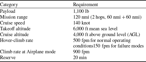
For the design of a hybrid power system for eVTOL aircraft, the initial sizing methodology started by defining a mission profile modelled on NASA’s 2-hop concept [Reference Patterson, Antcliff and Kohlman25] but with an extended range of 60 nmi per hop, aggregating to 120 nmi, as depicted in Fig. 1. The mission profile encompassed three distinct operational modes: Ground mode (grey line) including ‘Taxi’ for terrestrial locomotion; VTOL mode (blue line) including ‘Hover’, ‘Hover-Climb’, ‘Transition’, and ‘Descend’ for vertical flight; and Airplane mode (red line) covering ‘Acceleration + Climb’ and ‘Cruise’ for longitudinal flight. The tripartite categorisation facilitated an exhaustive analysis of aircraft capabilities across diverse flight states. The transition from VTOL to Airplane mode presented significant predictive challenges in the initial sizing [Reference Yu, Chen, Wang, Yan and Yuan36]; therefore, in this study, the transition is assumed to be a hover phase. The climb rate in Airplane mode was 900 fpm. The descent phase of the Airplane mode was replaced by cruise flight as a conservative approach [Reference Patterson, Antcliff and Kohlman25], which aligned with the standard aircraft design philosophy. Furthermore, this study ensured that the takeoff and cruise altitude conditions, as well as the reserve flight requirements, are congruent with the findings of NASA. By aligning these aspects, as detailed in Table 1, with a payload of 1100 lb and cruise speed of 140 knots, the vehicle requirements reflected the UAM mission profile proposed by NASA. This alignment ensuring consistency of this study with established research in the field. The hover-climb rates, complying with 14 CFR Parts 27 and 29, Category A, were normally set at 500 and 150 fpm under failure modes. In the mission profile for sizing the eVTOL aircraft consists of a nominal mission composed of two separate hops and an additional reserve flight for more than 20 minute.
Vehicle requirement

Sizing mission profile: two hops nominal mission with an additional reserve flight.

2.2 Retrofit of a generic quad tiltrotor aircraft
This study focused on extending the range of electric aircraft by converting them from a purely battery-powered system to a hybrid electric power system on a generic quad tiltrotor aircraft. The shift in propulsion systems was intended to enable longer flight distances, thereby offering improved performance without necessitating modifications to the airframe or payload. However, a key requirement for this retrofit was ensuring that the gross weight of the aircraft equipped with the hybrid electric propulsion system did not exceed the maximum allowable gross weight of the existing airframe. To analyse the failure modes based on the battery location, two different battery locations for the generic quad tiltrotor aircraft are defined as shown in Fig. 2. The generic quad tiltrotor aircraft consists of two main wings and a single vertical tail wing with four tiltrotors. The hybrid power system configuration has a TG and fuel tank located in the fuselage, whereas battery packs are located either in the fuselage or in the nacelles. Figure 2a shows the battery packs installed inside the nacelles; Fig. 2b shows the battery packs installed inside the fuselage. The battery location not only determines the physical separation of components but also affects the types of coupled failures that must be considered. In the battery layout within fuselage, the battery and propulsion units are spatially separated, so only three independent failure modes are relevant: OEI, OBI and OPI. By contrast, in the battery layout within nacelle, the battery, motor and proprotor are colocated within a confined structure, creating the possibility of compounded OPI+OBI failures. Such coupled failures may occur not only due to internal malfunctions of the motor-inverter and battery systems but also from external events. Because eVTOL aircraft operate predominantly at low altitudes, they are inherently more exposed to bird strike hazards. A direct impact on the nacelle or proprotor could simultaneously damage the propulsion system and the battery pack housed within the same nacelle, leading to a combined OPI+OBI failure. This highlights the need to consider OPI+OBI in battery layouts within the nacelle, whereas it remains irrelevant for those within the fuselage.
Generic quad tiltrotor aircraft.

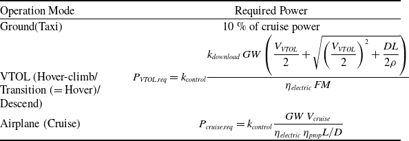
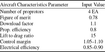
The performance prediction model in Table 2, which is rooted in momentum theory, correlates with the three operation modes defined in the mission profile. i.e. Ground, VTOL, and Airplane modes, providing a comprehensive approach for evaluating aircraft performance [Reference Leishman20, Reference Raymer27]. The essential input variables for aircraft performance calculations are listed in Table 3. The control margin and electrical efficiency were applied differently depending on flight mode. The control margin was 1.1 in VTOL mode, which consumed more power, and 1.05 in cruise mode. The electrical efficiency was 0.9 in cruise mode, which consumed more energy, and 0.85 in VTOL mode. However, the control margin was excluded from the energy calculation because of its use to calculate the maximum power requirement.
Simplified performance estimation model

Assumed parameters related to aircraft characteristics

2.3 Hybrid electric propulsion system
In the application of a series hybrid propulsion system that provides only electric power to the generic quad tiltrotor aircraft, as depicted in the hybrid power flow chart in Fig. 3, all four proprotors are individually powered by their own set of dual redundant electric motors. The redundancy of dual inverters for every motor ensures that a solitary fault in the motor or inverter does not lead to OPI failure, thereby maintaining system reliability. This hybrid system is designed with four battery packs and either single or twin TG configurations to supply the necessary power for specific mission segments. The power is then efficiently distributed and managed via a power management and distribution (PMAD) unit, which channels electricity to each inverter, while also enabling the recharging of some energy. This system requires the calculation of the power ratio between the TG and battery, which is a critical parameter for delivering power to each electric motor and charging the batteries. The hybrid power ratio is mathematically defined using Equation (1), which represents the proportion of the electrical power drawn from the battery relative to the total useful power [Reference Isikveren, Kaiser, Pornet and Vratny17]. The hybrid power ratio (
 ${H_p}$
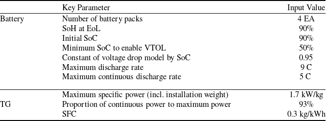
) is determined to be 0 when the aircraft operates solely on TG power and 1 when the aircraft relies entirely on battery power. The hybrid power ratio between 0 and 1 represents the percentage of combined use of TG and battery power. A negative hybrid power ratio value indicates that the TG charges the battery. The variability in hybrid power ratio, which is contingent on various flight segments and operational conditions, guides the sizing of hybrid power systems. The initial sizing was extensively analysed using a simplified propulsion system model. It was assumed that the TG-specific power and specific fuel consumption (SFC) remained constant, despite real-world variations, owing to factors such as altitude and operating conditions. Equation (2) establishes an effectiveness factor that depends on the battery’s state of charge (SoC) incorporating a standard constant representative of the battery model. Table 4 presents a detailed summary of the key parameters for both the TG and batteries in the hybrid power system. A simplified battery cell model [Reference Wang, Diepolder, Zhang, Söpper and Holzapfel33] was employed to address the voltage drop caused by the residual capacity.
 \begin{align}{H_p} = \frac{{{P_{bat}}}}{{{P_{bat}} + {P_{TG}}}}\end{align}
where
-
(a) TG only:
${H_p} = 0$
-
(b) Battery discharge only:
${H_p} = 1$
-
(c) TG + Battery discharge:
$0 \lt {H_p} \lt 1$
-
(d) TG + Battery charge:
${H_{}} \lt 0;\,\,{P_{bat}} \lt 0$


 \begin{align}{\rm{\;}}{e_{bat. SoC}} = \frac{{SoC}}{{1 - \varepsilon \left( {1 - SoC} \right)}}\end{align}
Key parameters of hybrid power system

Hybrid power flow chart of a generic quad tiltrotor aircraft with series hybrid electric propulsion system.

3.0 Deterministic sizing methodology of hybrid power systems
3.1 Five sizing rules for hybrid power ratios
This section introduces five sizing rules designed to effectively allocate available power and energy in hybrid power systems. These sizing rules aim to achieve the minimum gross weight of the aircraft while ensuring safe flight even under various failure modes. The five sizing rules can be categorised into two power sizing rules (1 and 2) and three energy sizing rules (3–5). The power sizing rules determine the capacity of the key power components to ensure safe flight under both normal and failure modes. The energy sizing rules guide the efficient utilisation of the aviation jet fuel and battery energy for each mission profile, considering the characteristics of the power components. As the safe operation of the aircraft is a priority, power sizing rules take precedence over energy sizing rules. The five sizing rules for guiding hybrid power ratio are
-
1. Ensure safe operation of the battery and TG under normal modes.
-
2. Guarantee reliable VTOL performance under failure modes.
-
3. Prioritise the more efficient energy source during cruise.
-
4. Recharge the battery during nominal cruise.
-
5. Utilise the remaining battery energy during the reserve phase.
The first rule specifies safe battery power usage when operating a VTOL under normal flight mode, guiding the battery operation below the maximum continuous discharge rate. When operating at the maximum rated discharge rate, there is a risk of fire and degradation of battery performance. Such a strategy is the key to preserving the performance integrity of batteries, especially in the VTOL mode, thereby extending their lifecycle and minimising the need for frequent replacements. This approach ensures both the longevity of the batteries and the consistent operational efficiency of the aircraft.
The second rule focuses on the requirements of a hybrid power system to maintain robust VTOL functionality in any failure cases, thus allowing a safe VTOL flight, even when the battery has the lowest SoC after the reserve flight.
The third rule details the strategy for cruise flight operations; this gives precedence to utilising an energy source (fuel) with a higher specific energy for cruise flight with the longest flight time, aiming to reduce the weight of the energy payloads.
The fourth sizing rule guides the battery for charging during a nominal cruise flight, thereby facilitating efficient power management for the VTOL function. This includes maintaining a consistent SoC in the battery before and after the nominal mission, which aids straightforward energy consumption calculations.
The last sizing rule guides the aircraft to use all available energy sources for reserve flight; however, the utilisation of battery power has to be limited to the minimum SoC required to maintain VTOL capability. This enables setting the hybrid power ratio during a reserve flight, which only uses up to the SoC of the VTOL-enabled battery, and the rest uses fuel.
Hybrid power ratio at normal operations

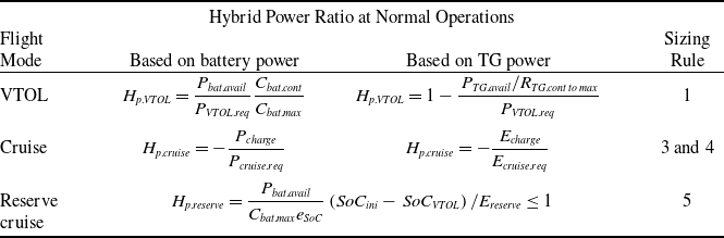
Consequently, with the exception of the second sizing rule, the other sizing rules (i.e. second through fifth rules) aid the calculation of the hybrid power ratios, and each one is tailored to specific operational conditions, as presented in Table 5. Calculation formulas for the hybrid power ratio in the VTOL and cruise modes based on the available battery and TG power have been proposed. The hybrid power ratio of the VTOL flight is calculated using the battery and TG power only up to the maximum continuous power on the VTOL flight, where the maximum power is required. The hybrid power ratio for cruise flight is calculated to charge the battery while using energy-efficient fuel because this is the most energy-consuming part of the flight. Because the reserve flight uses battery energy, the hybrid power ratio is calculated using the minimum SoC to enable VTOL(
 $So{C_{VTOL}}$
) and available battery energy based on the available battery power determined by the power required during the VTOL. The following sections describe the hybrid power ratios for various failure modes guided by the second sizing rule.
3.2 Sizing hybrid power system considering various failure modes
The second sizing rule is essential for determining the minimum available battery power sizing under the failure mode for a propulsion system. It is imperative to ensure a comprehensive safety analysis, defining the potential failure modes of eVTOL propulsion systems. Typically, for a conventional aircraft with engines, a single-engine failure is characterised as an OEI failure mode that is equivalent to a single TG failure in the eVTOL aircraft. In addition, a malfunction in one battery pack is categorised as an OBI failure mode. A failure involving the propeller or its associated motors constitutes the OPI failure mode. These are three general potential failure cases. However, when motors, propellers and batteries are integrated within a single nacelle, a more complex failure case is possible. This unique configuration can result in a combined OPI+OBI event, particularly in situations such as a battery fire triggered by bird-strike damage to the nacelle. Therefore, it is necessary to account for all four failure modes. By separately analysing the three- and four-failure cases, this study provides a comparative assessment of the sizing outcomes under different battery placement scenarios.
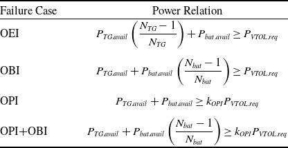
Table 6 summarises the relation between the available component power and the required aircraft power in each failure case.
 $N$
denotes the number of components. In the OEI case of a single-TG aircraft, the battery packs must supply sufficient power to meet the flight demand within the operational limits. For multi-TG aircraft, if one TG fails, the remaining TGs and the battery packs must compensate for the lost power. Similarly, in the case of OBI, the remaining battery packs and the TGs share the power load. The required power also differs between normal and OPI modes. In the event of OPI, the remaining proprotors must sustain a higher disk loading than in the normal mode, resulting in an increased total power requirement. For example, if one proprotor of the quad tiltrotor fails, the diagonally opposite proprotor is also deactivated to maintain balance. Consequently, the remaining two proprotors must generate twice the thrust to compensate for the loss. The power required in OPI can be expressed by the power overhead factor,
 ${k_{OPI}}$
, as shown in Equation (3), where
 $DL$
denotes the disk loading under normal mode.
 ${N_{proprotor\;}}$
denotes the number of operative proprotors, which is four under normal mode and two under OPI for a quad tiltrotor aircraft. This value is configuration-specific and may differ for other designs.
Relation between available component power and aircraft power required in each case

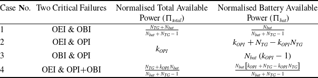
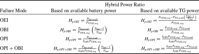
The capacity of each power source in the eVTOL aircraft is primarily determined by the VTOL phase, which imposes the highest power requirement. The available capacities are normalised with respect to the required power to determine the minimum total available power across the failure modes, as shown in Equation (4). In this equation, the total available power is the sum of the battery and TG contributions. The battery power is likewise normalised against the required power, as given in Equation (5). Using these normalised expressions, the sizing process begins by defining four representative binding pairs of flight modes – OEI–OBI, OEI–OPI, OBI–OPI and OEI–OPI+OBI. Each pair constitutes a sizing case that constrains the minimum required power capacities of both the TG and the battery. For each case, two power-balance equations can be written at the corresponding VTOL demand points, as summarised in Table 7. The critical failures are identified by comparing the normalised total available power under the potential failure cases. When considering the three failure modes, two critical cases are determined from the comparison of Cases 1–3; these may vary depending on the number of battery packs and TGs. In contrast, when all four failure modes are included, the OEI and OPI+OBI cases are consistently critical for maintaining positive battery power. Once these two critical cases are determined, the minimum available battery power can be calculated using the equations in Table 7. The resulting hybrid power ratio for each failure mode, based on the available battery and TG power, is listed in Table 8.
 \begin{align}{k_{OPI}} = \frac{{{P_{OPI.req}}}}{{{P_{VTOL.req}}}}\; = \frac{{\frac{{{V_{climb.failure}}}}{2} + \sqrt {{{\left( {\frac{{{V_{climb.failure}}}}{2}} \right)}^2} + \frac{{{N_{proprotor.normal\;}}}}{{{N_{proprotor.OPI}}}}\frac{{DL}}{{2\rho }}} }}{{\frac{{{V_{climb.failure}}}}{2} + \sqrt {{{\left( {\frac{{{V_{climb.failure}}}}{2}} \right)}^2} + \frac{{DL}}{{2\rho }}} }}\end{align}
 \begin{align}{{\rm{\Pi }}_{total}} = \frac{{{P_{bat.avail}} + {P_{TG.avail}}}}{{{P_{VTOL.req}}}}\;\;\;\end{align}
 \begin{align}{{\rm{\Pi }}_{bat}} = \frac{{{P_{bat.avail}}}}{{{P_{VTOL.req}}}}\end{align}
Normalised available power in each case

Hybrid power ratio for each failure mode

3.3 Initial sizing process of optimal hybrid power system
An initial sizing flow chart for the eVTOL aircraft focusing on sizing the hybrid power system is shown in Fig. 4. The initial target gross weight is set, and the aircraft performance for the mission profile is calculated. The initial sizing of the hybrid power system is performed using the required power to satisfy the performance. The total gross weight, including the weight of the hybrid power system, is calculated. If it is equal to the initial target gross weight, the process is terminated; otherwise, the initial target gross weight is updated and the process is repeated. The initial sizing is an iterative process in which the predicted performance and weight of the aircraft are calculated. The sizing method described in Section 3.2 is applied to determine the optimal hybrid power system. The optimal hybrid power system is defined as the minimum-weight power supply system capable of ensuring safe flight. Because hybrid power systems combine multiple power sources, the optimal hybrid power system can be configured by applying different approaches, depending on the relative technological maturity of the two power sources. When the TG technology is more advanced than the battery, a minimum battery sizing method is applied. Conversely, when the battery technology is superior to the TG, a minimum TG sizing method is used.
Flow chart of sizing hybrid power system.

The minimum battery sizing determines the optimal battery capacity that minimises excess power for a given TG configuration. This process requires identifying the most critical failure cases and establishing boundary conditions for zero excess power. The available battery power in the minimum battery case is expressed in normalised form in Table 7 and calculated using Equation (6). Subsequently, the TG capacity is obtained by comparing the required power under both normal and failure modes, as shown in Equation (7). It should be emphasised that the hybrid power system sizing assumes the specific energy of the TG to be superior to that of the battery, thereby justifying the use of the TG during cruise. Accordingly, the lower limit of the TG continuous power in the minimum TG approach is defined as the sum of the required cruise power and the excess power necessary for battery charging, as given in Equation (8). The maximum rated power of the TG can then be derived using the ratio of maximum continuous to maximum rated power, denoted as
 ${R_{TG.cont\;to\;max}}$
. Another assumption, applicable beyond the minimum TG approach, is the presence of at least two battery packs. This ensures that the TG is sized primarily with respect to the OBI mode, rather than cruise, in the case of single-pack failures. The maximum available battery power is determined by comparing VTOL power requirements under both normal and failure scenarios, as presented in Equation (9). The hybrid power ratios corresponding to each failure case are then calculated using the formulations in Table 8. The available fuel energy, corresponding to the fuel-system weight, can be reformulated as a function of available battery power by applying the hybrid power ratio for the reserve segment from Table 5, as expressed in Equation (10). The key input parameters used in this process are listed in Table 4. The overall hybrid system weight is finally estimated through a set of equations linking the weights of the TG, battery and fuel, as given in Equation (11). These weight calculations account for specific power and, in the case of the battery, incorporate the influence of SoC and state of health (SoH) at end-of-life (EoL).
 \begin{align}{\rm{\;}}{P_{bat.avail@min.{\rm{\;}}bat}} = {{\rm{\Pi }}_{bat}}_{VTOL.req}{\rm{\;\;\;}}\end{align}
 \begin{align}{P_{TG.avail@min.bat{\rm{\;}}}} = max\left[ {\begin{array}{*{20}{c}}{{{\left( {\frac{{{P_{cruise.req}}\left( {1 - {H_{p.cruise}}} \right)}}{{{R_{TG.cont{\rm{\;}}to{\rm{\;}}max}}}}} \right)}_{cruise}},{{\left( {\frac{{{P_{VTOL.req}}\left( {1 - {H_{p.VTOL}}} \right){\rm{\;}}}}{{{R_{TG,cont{\rm{\;}}to{\rm{\;}}max}}}}} \right)}_{normal}},}\\{{{\left( {\left( {1 - {H_{p.OEI}}} \right){P_{VTOL.req}}\frac{{{N_{TG}}}}{{{N_{TG}} - 1}}} \right)}_{OEI}},{{\left( {\left( {1 - {H_{p.OBI}}} \right){P_{VTOL.req}}} \right)}_{OBI}},}\\{{{\left( {\left( {1 - {H_{p.OPI}}} \right){k_{OPI}}{P_{VTOL.req}}} \right)}_{OPI}},{{\left( {\left( {1 - {H_{p.OPI + OBI}}} \right){k_{OPI}}{P_{VTOL.req}}} \right)}_{OPI + OBI}}}\end{array}} \right]\end{align}
 \begin{align}{\rm{\;}}{P_{TG.avail@min.TG}} = \left( {1 - {H_{p.cruise}}} \right)\frac{{{P_{cruise.req}}}}{{{R_{TG.cont{\rm{\;}}to{\rm{\;}}max}}}}{\rm{\;\;\;}}\end{align}
 \begin{align}{P_{bat.avail@min.TG}} = max\left[ {\begin{array}{*{20}{c}}{{{\left( {{H_{p.VTOL}}{P_{VTOL.req}}\frac{{{C_{bat.max}}}}{{{C_{bat.cont}}}}} \right)}_{normal}},}\\{{{\left( {{H_{p.OEI}}{P_{VTOL.req}}} \right)}_{OEI}},{{\left( {{H_{p,OBI}}{P_{VTOL.req}}\frac{{{N_{bat}}}}{{{N_{bat}} - 1}}} \right)}_{OBI}},}\\{{{\left( {{H_{p.OPI}}{k_{OPI}}{P_{VTOL.req}}} \right)}_{OPI}},{{\left( {{H_{p.OPI + OBI}}{k_{OPI}}{P_{VTOL.req}}\frac{{{N_{bat}}}}{{{N_{bat}} - 1}}} \right)}_{OPI + OBI}}}\end{array}} \right]\end{align}
 \begin{align}{E_{fuel.avail}} = {E_{nominal}} + \left( {1 - {H_{p.reserve}}} \right)\;{E_{reserve}} = {E_{nominal}} + {E_{reserve}} - {P_{bat,avail}}\frac{{So{C_{ini}} - So{C_{min}}}}{{{e_{SoC.min}}{C_{bat.max}}}}\end{align}
 \begin{align}{W_{HS}} = \left[ {\frac{1}{{{e_{SoC.min}}\;So{H_{EoL}}S{P_{Bat}}}}{P_{bat.avail}} + \frac{1}{{S{P_{TG}}}}{P_{TG.avail}} + {k_{fuel}}SFC\;{E_{fuel.avail}}} \right] \\[8pt] \nonumber \end{align}
The disparity in technological maturity between batteries and TGs necessitates distinct sizing methodologies, which yield differing outcomes. Nevertheless, a convergence point exists where the optimal weight of both approaches coincide. By deriving the equation at this intersection, one can identify the critical factor that determines whether the minimum battery of minimum TG sizing method should be applied. This intersection, termed the sizing transition threshold, occurs when the weight fraction obtained from the minimum battery approach equals that from the minimum TG approach, as defined in Equation (12). Equation (13) is derived by substituting the respective contributions of the battery and TG into the hybrid power ratio, consistent with the definitions in Table 8. In this study, the sizing point is defined as the flight mode that demands the highest power during vertical climb across all potential failures (OEI, OBI, OPI, OPI+OBI). An argument of sizing point,
 ${\theta _{sizing\;point}}$
, therefore depends on which case imposes the maximum requirement, as formalised in Equation (14). Table 9 summarises the argument associated with each sizing point. Finally, to satisfy Equation (13), the term within the brackets must equate to zero. This evaluation criterion establishes the critical specific power of the battery system at the sizing transition point, expressed in Equation (15). When the applied battery-specific power is lower than this threshold, it indicates that the battery technology is relatively less mature, and the minimum battery sizing method should be applied. Conversely, when the battery-specific power exceeds this value, it suggests that the battery technology is more advanced than that of the TG, in which case the minimum TG sizing method should be employed.
 \begin{align}{\left( {{W_{bat}} + {W_{TG}} + {W_{fuel}}} \right)_{min.bat}} = {\left( {{W_{bat}} + {W_{TG}} + {W_{fuel}}} \right)_{min.TG}}\end{align}
 \begin{align*}\left( {{H_{P.sizing\;point@min.bat}} - {H_{P.sizing\;point@min.TG}}} \right)\end{align*}
 \begin{align}\left[ {\frac{1}{{{e_{SoC.min}}So{H_{EoL}}S{P_{bat}}}} - \frac{1}{{S{P_{TG}}}}{\theta _{sizing\;point}} - \frac{{{k_{fuel}}SFC\;\left( {So{C_{ini}} - So{C_{min}}} \right)}}{{\;{C_{bat.max}}{e_{SoC.min}}}}} \right] = 0\end{align}
 \begin{align}sizing\;point = arg \mathop {max }\limits_{i \in \left\{ {Potential\;failure\;modes} \right\}} {{\rm{\Pi }}_{bat@i}}\end{align}
 \begin{align}S{P_{bat.crit}} = \frac{1}{{\;{e_{SoC.min}}\;So{H_{EoL}}\;\left[ {\frac{1}{{S{P_{TG}}}}{\theta _{sizing\;point}} + \frac{{{k_{fuel}}SFC\left( {So{C_{ini}} - \;So{C_{min}}} \right)}}{{{C_{bat.max}}{e_{SoC.min}}}}} \right]}}\end{align}
Argument of each sizing point

4.0 Result and discussion
4.1 Deterministic hybrid power system considering three failure modes
This section presents the initial sizing results considering the three failure modes (OEI, OBI and OPI) wherein the battery packs are installed inside the fuselage. The study maintains constant values for the airframe and payload to concentrate on analysing the hybrid power system. As components of hybrid power systems, TGs have reached sufficient technological maturity. In contrast, battery technology is in a state of ongoing development. This analysis includes a detailed exploration of the various technological levels of the battery system. Figure 5 depicts a gross weight comparison based on the technological maturity of the battery-specific energy for hybrid power systems with single and twin TGs. For confidentiality reasons, the absolute values of the fixed airframe weight cannot be disclosed, as they are based on proprietary industrial data. Instead, the results are presented in terms of relative weight fractions, which preserve the overall sizing trends and clearly illustrate the influence of battery placement and failure modes without requiring access to proprietary values. Figure 5a shows the results of applying the minimum battery sizing method when the TG technology is superior to the battery. Evidently, the higher the battery-specific energy, the lighter the gross weight of the aircraft. The trend slopes for the designed results have different gross weight slopes for the battery technologies used, depending on whether it is a single or twin TG hybrid system; therefore, there is an intersection point with the same gross weight. When the specific energy of the battery pack is below the threshold of 310 Wh/kg at the first intersection point, the twin TG can be used to design a lighter aircraft. Conversely, if the specific energy is higher than this threshold, the single TG can be used to design a lighter aircraft. Figure 5b shows the results of applying the minimum TG sizing method when the battery technology is superior to the TG. The minimum TG sizing method yields identical gross weights for the single and twin TGs. When the hybrid system is designed with the minimum TG, the battery has sufficient power to enable battery-only operation under the OEI failure mode, as shown in Fig. A3a in the Appendix. This results in no difference in total weight between single TG and twin TGs. As battery technology improves, the minimum TG sizing method enables the design of a lighter aircraft compared to the minimum battery sizing method. The second intersection point (341 Wh/kg) at which the same gross weight can be designed using both sizing methods is identified. This intersection point serves as the criterion for selecting between two deterministic initial sizing approaches. Figure 6 illustrates the optimal sizing results for the three failure modes. When the battery technology exceeds the second intersection point, the minimum TG sizing method should be applied to the hybrid power system. Conversely, for battery technologies below this point, the minimum battery sizing method is appropriate. In particular, if the specific energy is below the first intersection point (310 Wh/kg), a twin-TG configuration must be adopted; if it lies between the first (310 Wh/kg) and second (341 Wh/kg) points, a single-TG configuration is recommended.
Gross weight comparison based on technological maturity of battery-specific energy.

Optimal gross weight based on technological maturity of battery-specific energy.

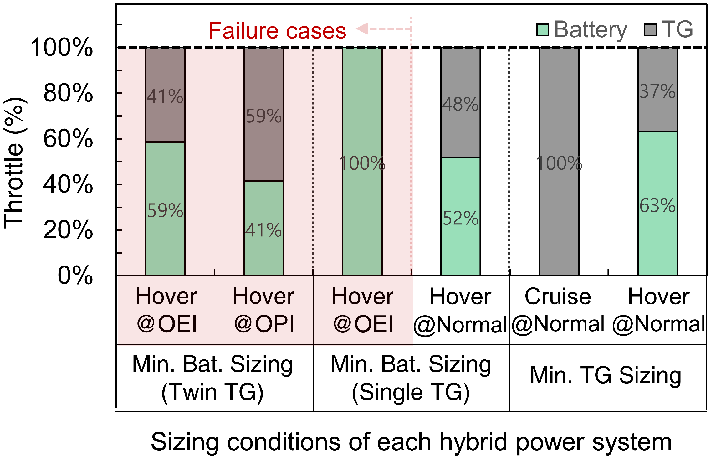
To determine the initial sizing, the hybrid power usage for each critical flight mode was analysed considering the three failure modes for each hybrid power system, as shown in Fig. 7. The shaded red colour indicates failure mode. Considering the three failure modes in the hybrid system, each hybrid power system has different sizing conditions. The twin TG hybrid power system of the minimum battery sizing method determines the available power capacity based on the VTOL (Hover-Climb) flight in the OEI and OPI cases. The single TG hybrid power system of the minimum battery sizing method determines the available power capacity based on the VTOL flight at the OEI and normal modes. The hybrid power system of the minimum TG sizing method determines the available power capacity based on cruise and VTOL flight under normal modes. The minimum TG sizing method determines the hybrid power system under normal flight states based on the maximum continuous power, whereas the minimum battery sizing method determines the hybrid power system under failure cases based on the maximum rated power. If the sizing results for the single and twin TG configurations are identical for the minimum battery sizing method, it is advisable to select the twin TG configuration with a power margin during normal operations for development, as shown in Figs A1 and A2 in the Appendix. At a battery-specific energy of 341 Wh/kg, the same sizing results (i.e. gross weights) are obtained for the hybrid power systems with various deterministic hybrid power ratios, thus implying that many different combinations of batteries and TG power comprised a hybrid system. Although battery systems can be easily configured for the desired power, the TG power has limited options because of the use of off-the-shelf products. Consequently, when developing an optimal hybrid power system for an aircraft, it is advantageous to configure it at the intersection where the minimum battery and TG sizing methods yield the identical result. This intersection corresponds to the sizing transition threshold introduced in Section 3.3, which produces the same result as derived in Equation (15).
Hybrid power usage considering the three failure modes.

Gross weight comparison based on technological maturity of battery-specific energy considering the four and three failure modes.

4.2 Comparison between three and four failure modes
This section extends the analysis to compare the sizing results under four failure modes, factoring in the conditions where both OPI and OBI occur simultaneously. Figure 8 shows a continuation of the analysis from Fig. 6. The analysis, which focuses on the four failure modes, is represented using a dotted line, consistently following the same symbolic representation for each sizing method. Depending on the applied battery technology, considering the OPI + OBI case in the initial sizing, the gross weight of the aircraft increases by approximately 50–300 lb. This increase can be attributed to the need for additional power capacity because the two failure modes occur simultaneously. The selection criteria for the sizing methodology used to derive the optimal gross weight of the aircraft depend on the type of failure identified. The weight of the hybrid power system designed with a battery-specific energy of 274 Wh/kg is the same regardless of the minimum battery and TG sizing method and TG configuration. A detailed analysis is described in the Appendix. Considering the four failure modes, results of the minimum battery sizing method, applied when the battery technology maturity is relatively low, shows that a twin TGs are more optimal than a single TGs for designing hybrid power systems. As battery technology improves, the minimum TG sizing method can be used to design an optimal hybrid power system. In addition, it is also important to remember that the assumption is that the existing airframe is used, so exceeding the maximum takeoff weight (MTOW) of the existing airframe is not feasible. Feasible results are a battery-specific energy greater than 240 Wh/kg for the three failure modes and greater than 300 Wh/kg for the four failure modes. As shown in Fig. 9, the initial sizing of the minimum battery sizing method is based on the single and twin TGs. For both cases, the hybrid VTOL power capacity is determined by the failure modes, namely the OEI and OPI+OBI modes. The minimum TG sizing result is determined by the TG power required for normal cruise and the power demand under the OPI+OBI failure mode during VTOL operation. Considering the four failure modes, for both the single and twin TGs with the minimum battery sizing, the sizing flight conditions that determine maximum power are identical for the OEI and OPI+OBI failure modes, with the only difference being the minimum TG sizing method. The minimum TG sizing method is characterised by the cruise mode, where the minimum power required is determined according to the sizing rules 3 and 4, and the battery system is determined to be sufficient to supply the remaining power, excluding TG power, in the most severe failure mode, OPI+OBI. This results in a single intersection point. Because all three hybrid power systems are designed based on the OPI+OBI mode, which is the failure mode, they all have the same gross weight at a battery-specific energy of 274 Wh/kg. The second intersection point of the design method considering the three failure modes is 341 Wh/kg, while the single intersection point of the design method considering four failure modes is 274 Wh/kg, which is 67 Wh/kg lower. These intersection points are determined by considering the technology level of the battery and TG based on the failure mode being considered. In particular, the ratio of the maximum continuous power to the maximum rated power of the battery (56%) is significantly lower than that of the TG (93%). This difference leads to a lower intersection point for the hybrid power system considering the four failure modes.
Hybrid power usage considering four failure modes.

Table 10 summarises the deterministic hybrid power ratios of the onboard hybrid power system. The minimum battery sizing method allocates the remaining required power to the TG based on the minimum battery power required considering normal and failure modes, reducing the deterministic hybrid power ratio when considering the four failure modes. The minimum TG sizing method determines the maximum battery power based on the minimum TG power required under normal cruise mode, which results in a higher deterministic hybrid power ratio when considering the four failure modes. As more severe failure modes are considered, the deterministic hybrid ratio presented by the methodology in this study, a lower hybrid power ratio when the battery technology is worse than the TG, and a higher hybrid ratio when the battery technology is better than the TG. It can be confirmed that the methodology presented in this paper, namely the minimum battery and TG sizing approach, works as intended.
Deterministic hybrid power ratios of onboard hybrid power system

Placing the battery in a location other than the nacelle would have resulted in a lighter aircraft design with only three failure modes considered, without considering OPI+OBI. The initial sizing results and analysis highlighted the importance of the battery location from the beginning of the aircraft design through the identified failure modes.
4.3 Uncertainties and limitations
This section discusses the inherent uncertainties and limitations of the hybrid power system model used for the eVTOL aircraft, along with the assumptions made in this study. To conduct an in-depth exploration of the initial sizing methodologies for hybrid power systems, it was assumed that the airframe weight was constant. This assumption was illustrated in a retrofit, in which the propulsion system of an existing battery-powered aircraft was replaced with a hybrid power system. The key constraint in this retrofit was the design of a hybrid power source such that its weight, combined with the airframe and payload weights, did not exceed the airframe’s maximum gross weight capacity. This assumption enabled exclusive focus on the hybrid power source sizing without the complexities of varying airframe weights.
A simplified battery model for SoC was used in this study. Although effective for the scope of this study and developed to mitigate the impact of the battery SoC on the available power, this model introduces inherent uncertainty. The simplified battery SoC model, while aiding in reducing the complexity of the analysis, fails to fully capture the nuanced effects of SoC variations on the available power of the battery in a real environment. The necessity of balancing the model complexity with computational feasibility leads to a certain level of uncertainty. As such, this study contributes to minimising the impact of battery SoC on power availability; however, the uncertainties arising from the simplified SoC model cannot be completely eliminated. This limitation underscores the need for future research on more developed battery models that can accurately reflect the dynamic nature of the battery SoC and its impact on the hybrid power system in eVTOL aircraft.
This study relied heavily on simplified performance models and static efficiency values. Basic technical parameters, such as the specific energies of the battery and fuel system, along with the specific power of the TG, were chosen for simplicity. Although practical for simplifying the initial analysis, this approach introduces a notable degree of uncertainty. This uncertainty is primarily due to variations in the TG configurations (single vs. twin), each with different accessory weights, and the influence of various operating environments such as altitude, temperature, humidity and power throttle settings. However, simplifying these aspects is necessary in the initial design phase for obtaining the optimal values of the critical parameters of interest. In future studies, specific power values for TGs that vary under different operating conditions and environmental factors will be used to increase the fidelity of the model.
5.0 Conclusions
This study developed an optimal hybrid power system design by applying a deterministic hybrid power ratio, considering several failure modes depending on the battery installation location. The investigation was conducted on a series gas turbine hybrid electric propulsion system for the generic quad tiltrotor aircraft. Based on the battery placement, the failure modes were categorised into two groups. In the typical eVTOL layout, the battery is located within the fuselage, and the three failure modes are identified: OEI, OBI and OPI. Because the battery and propulsion units are spatially separated in this configuration, a coupled OPI+OBI failure is not considered. By contrast, in battery layouts within the nacelle, where the battery and motor share the same nacelle, the combined OPI+OBI case is also examined. Such coupled failures may occur due to internal system malfunctions or external hazards, such as bird strikes at low altitude, which can simultaneously damage both the battery and the proprotor housed within the same nacelle. This structural distinction necessitates consideration of four potential failure cases with interconnected failure modes unique to battery layouts within the nacelle.
The deterministic hybrid power ratio of the hybrid power system, determined by the applied sizing methods, was compared to the single and twin TG configurations. When considering the three failure modes, as battery technology improves, the minimum battery sizing for the twin TG, and next the single TG, next the minimum TG sizing can result in an optimal hybrid power system design. Interestingly, when considering the four failure modes, designed with the minimum battery sizing, the twin TG results in lighter aircraft than the single TG. In addition, considering the three failure modes, the hybrid power system always results in lighter aircraft designs. Therefore, when considering more severe failure modes such as OPI+OBI, the system becomes heavier owing to the need to accommodate higher power requirements.
This study demonstrated that different battery placements can have different failure modes, which in turn affect the deterministic hybrid power ratio. The findings also provide important guidance for organising optimal hybrid power systems. In addition, this study identified the most suitable TG configuration for the current state of battery technology when configuring hybrid power systems. However, certain limitations exist, namely, the use of a simplified propulsion model and assumption of fixed airframe weights. In the future, to achieve more refined sizing results, a more advanced model for hybrid power system will be adopted, and variable airframe weights will be considered.
Acknowledgments
This work was supported by the Korea Agency for Infrastructure Technology Advancement (KAIA) grant funded by the Ministry of Land, Infrastructure, and Transport (Grant RS-2022-00143965). The authors also acknowledge the support of Hanwha Systems, whose contribution was essential to the successful completion of the project. The first author wishes to thank his wife and daughter for their continued encouragement and understanding throughout the course of this research.
Competing interests
The authors declare none.
Appendix
A.1. Sizing conditions for each hybrid power system
By applying the minimum battery and TG sizing approaches, the power consumption of the single and twin TG hybrid power systems was analysed for each flight condition. Figure A1 shows the hybrid power usage for a single TG hybrid power system, determined using the minimum battery sizing approach. Figure A1a shows the hybrid power system determined by considering three failure modes; Fig. A1b shows the hybrid power system determined by considering four failure modes. An optimal hybrid power system should utilise the maximum hybrid power in both flight states. We observed that both the hybrid power systems considering three and four failure modes used the maximum hybrid power under the OEI sizing condition, which was the failure mode. The hybrid power system that considered the three failure modes was the maximum hybrid power used under normal conditions over the climbing flight segment. A hybrid power system considering the four failure modes was used with a full hybrid power throttle in the hover-climb flight segment of OPI + OBI, which was an additional failure mode. The hybrid power usage of the twin TG hybrid power system, as determined by the minimum battery sizing approach, is shown in Fig. A2. The twin TG hybrid power system also allows the full hybrid power throttle to be used in the OEI failure mode, and the remaining operable TG power can be used in conjunction with the battery power, allowing more TG power to be allocated when the battery technology is not mature, resulting in a lighter hybrid power system than a single TG. Unlike a single TG, a twin TG hybrid power system that considers the three failure modes utilises the maximum hybrid power in the OPI failure mode. Twin TG hybrid power systems considering four failure modes were designed to utilise the maximum hybrid power for the same flight conditions as single TGs but with different hybrid power ratios. Both hybrid power systems considering three and four failure modes used the maximum hybrid power only under failure conditions. The minimum battery sizing approach determines the available battery power in the OEI failure mode; therefore, when the battery is immature, the twin TG system uses hybrid power by minimising the battery power, allowing a lighter hybrid power system to be designed. The hybrid power usage in the hybrid power system, determined using the minimum TG sizing approach, is shown in Fig. A3, with the same results for single and twin TGs. The hybrid power system is designed to operate on battery power alone in OEI failure mode, with the required power for the remaining flight conditions allocated to battery power once the minimum TG power is determined. Therefore, the minimum TG sizing approach determines the same hybrid power system regardless of whether the TGs are single or twin. As shown in Fig. A3a, the hybrid power system considering the three failure modes uses the maximum hybrid power in the cruise and hover-climb flight segments under normal flight modes. As shown in Figure A3b, the hybrid power system considering the four failure modes uses the maximum hybrid power in cruise under normal flight modes and in the flight segment of the OPI+OBI failure mode.
Hybrid power usage for single TG configuration determined by min. battery sizing.

Hybrid power usage for twin TG configuration determined by min. battery sizing.

A.2. Aircraft mission analysis for each hybrid power system
Hybrid power usage for the hybrid power system determined by min. TG sizing.

Aircraft mission analysis across each flight segment under normal operating conditions for the hybrid power system considering four failure modes.

Figure A4 illustrates the aircraft mission analysis across each flight segment under normal operating conditions for the hybrid power system, considering four failure modes. A comparison of hybrid power systems considering three and four failure modes showed similar results under normal operating conditions. Therefore, only the hybrid power systems determined for the four failure modes were discussed in the aircraft mission analysis. The results for the single TG hybrid power system determined using the minimum battery size approach are shown in Fig. A4a; the twin TG hybrid power system determined using the minimum battery size approach is shown in Fig. A4b and the hybrid power system determined using the minimum TG size approach is shown in Fig. A4c. All hybrid power systems were designed with a battery technology level of 274 Wh/kg to compare the same gross aircraft weight. In this graph, the horizontal axis represents the mission segments based on the mission profile, and the final segment depicts the flight segment of the cruise during the reserve flight. The remaining energy is indicated on the left vertical axis, and the power consumption of the power source is shown on the right vertical axis. The hybrid power ratio is shown as a green number at the bottom of the bar graph, with a positive number indicating battery discharge and a negative number indicating charge. In accordance with the energy sizing rule #3, during the cruise mode, the aviation jet fuel, recognised for its higher specific energy in the hybrid energy source, is primarily consumed by the battery in a charging state. The hybrid power ratio for the ‘cruise’ flight segment ranges from −0.1 to −0.3, depending on the battery capacity of each system. In addition, the maximum charge rate during battery charging is used as a constraint in the initial sizing. The maximum charge rate was set to no more than 1.5 C; thus, the results were used within 1.2 C. The hybrid power systems, determined by the minimum battery sizing approach, use more TG power under normal operating conditions; a twin TG system can further maximise this tendency. Therefore, when battery technology is not mature, configuring a twin TG system with the minimum battery sizing approach may result in a lighter hybrid power system. The hybrid power systems determined by the minimum TG sizing approach use relatively more battery power under normal operating conditions. Therefore, as battery technology matures, configuring a hybrid power system using the minimum TG sizing approach may result in a lighter hybrid power system.