1 Introduction
Taylor–Couette (TC) flow, the flow between two coaxial and independently rotating cylinders, can present different types of transition to turbulence. For vanishing viscosity, TC flow is linearly unstable if
 $|r_{o}{\it\omega}_{o}|<|r_{i}{\it\omega}_{i}|$
, where
 $r_{i,o}$
are the radii of the inner and outer cylinders, and
 ${\it\omega}_{i,o}$
their angular velocities (Rayleigh Reference Rayleigh1917), due to the centrifugal forces. If viscosity is considered, a minimum rotation strength is required to overcome the viscous damping. For pure inner cylinder rotation, once this stability threshold is crossed, TC flow presents a supercritical transition to turbulence, where the purely azimuthal flow develops large-scale structures that fill up the entire gap and effectively redistribute angular momentum (Taylor Reference Taylor1923; Fardin, Perge & Taberlet Reference Fardin, Perge and Taberlet2014). With increasing rotation, these large-scale structures undergo a series of transitions from laminar Taylor vortices to wavy Taylor vortices to modulated wavy Taylor vortices to turbulent Taylor vortices (Andereck, Liu & Swinney Reference Andereck, Liu and Swinney1986). Even at very large Reynolds numbers these structures have been observed to persist in some regions of the parameter space, i.e. at
 $Re\sim O(10^{5})$
in simulations (Ostilla-Monico et al.
Reference Ostilla-Monico, van der Poel, Verzicco, Grossmann and Lohse2014a
) and then at
 $Re\sim O(10^{6})$
in experiments (Huisman et al.
Reference Huisman, van der Veen, Sun and Lohse2014). The flow field shows a clear lack of statistical spatial homogeneity and these ‘rolls’ cause substantially large deviations of the near-wall velocity profiles of TC flow from the classic wall-turbulence profiles of channels and pipes. This effect has been attributed to the role of curvature and the centrifugal instability (Ostilla-Mónico et al.
Reference Ostilla-Mónico, Verzicco, Grossmann and Lohse2016). For an overview of supercritical TC flow at large Reynolds numbers, we refer the reader to the review of Grossmann, Lohse & Sun (Reference Grossmann, Lohse and Sun2016).
If, instead, the outer cylinder is rotated, and the inner cylinder is kept fixed, the flow undergoes a subcritical transition to turbulence. This transition is quite different from the supercritical transition detailed previously, as the flow does not go undergo a series of changes from less complex to more complex flow patterns, but instead makes a sudden transition to turbulence, either in localized spots or filling the entire gap. While Taylor (Reference Taylor1936) found evidence for this subcritical transition by measuring the torques and how they deviated from the predictions for steady flow, this transition was first systematically studied by Coles (Reference Coles1965), who found that for low outer cylinder Reynolds numbers,
 $Re_{o}=dr_{o}{\it\omega}_{o}/{\it\nu}$
with
 ${\it\nu}$
the fluid kinematic viscosity and
 $d$
the gap width,
 $d=r_{o}-r_{i}$
, intermittent turbulent patches coexisted with laminar flow, with well-defined interfaces. The persistence time of these patches increased with increasing inner cylinder Reynolds number
 $Re_{i}=d{\it\omega}_{i}r_{i}/{\it\nu}$
, and so did the turbulent fraction, until the flow was fully turbulent. For the lower
 $Re_{o}$
range, the flow had to be started in a supercritical state, such that the centrifugal instabilities provided an initial perturbation for the generation of turbulence. For larger values of
 $Re_{o}$
, the flow no longer required the centrifugal instability to transition to turbulence, and could remain exclusively in the subcritical region and still see a spontaneous, or ‘catastrophic’, transition to turbulence.
Studies of subcritical TC flow continued through the years, both theoretically, in an attempt to develop nonlinear stability criteria, as well as numerically and experimentally. The focus of many of these studies was on the sharp turbulent–laminar interface and on spiral turbulence, a particular flow where the bursts took a spiral shape (van Atta Reference van Atta1966; Andereck, Dickman & Swinney Reference Andereck, Dickman and Swinney1983). We refer the reader to the thesis of Borrero-Echeverry (Reference Borrero-Echeverry2014) for a detailed historical overview of studies of subcritical TC flow. Subcritical transitions to turbulence have been well studied in the past, and are an active area of research, because not only TC flow, but also pipe and channel flows present a subcritical transition to turbulence. For a comprehensive overview of this field, we refer the reader to the review by Eckhardt et al. (Reference Eckhardt, Faisst, Schmiegel and Schneider2008).
A recent systematic study of pure outer cylinder rotation (OCR) in TC flow was performed by Burin & Czarnocki (Reference Burin and Czarnocki2012), who experimentally studied in detail the effect of gap width and end-plate configurations on the transition to turbulence. These authors also performed velocimetry in the bulk and found that regions of high turbulence were associated with high shear. Earlier, Borrero-Echeverry, Schatz & Tagg (Reference Borrero-Echeverry, Schatz and Tagg2010) had already provided evidence for superexponential dependence on the Reynolds number of the decay times of turbulence. Therefore, it seems that outer cylinder TC flow with high Reynolds number is turbulent for extremely long time scales. This regime has not been well characterized: Burin & Czarnocki (Reference Burin and Czarnocki2012) did not provide velocimetry close to the walls. The other experimental studies by Paoletti & Lathrop (Reference Paoletti and Lathrop2011) and Paoletti et al. (Reference Paoletti, van Gils, Dubrulle, Sun, Lohse and Lathrop2012) only provided torque measurements for pure OCR, which indicated values well above the values for laminar flow but also much lower than the torque values for pure inner cylinder rotation. However, experiments are limited by the necessary presence of end plates to provide flow confinement, and this could potentially affect the physics. Numerical studies of pure OCR in an infinite (periodic) domain are limited to Deguchi, Meseguer & Mellibovsky (Reference Deguchi, Meseguer and Mellibovsky2014), who considered Reynolds numbers near the transition to turbulence.
In this article, we conducted a series of direct numerical simulations (DNS) of axially periodic and fully turbulent TC flow with only outer cylinder rotation, in an attempt to isolate and study subcritical behaviour of TC flow, and to eliminate the effect of perturbations arising at the end plates. We consider pure outer cylinder rotation because it does not have the complex combination of sub- and supercritical behaviour seen in turbulent counter-rotating TC flow (van Gils et al. Reference van Gils, Huisman, Grossmann, Sun and Lohse2012; Brauckmann & Eckhardt Reference Brauckmann and Eckhardt2013; Grossmann et al. Reference Grossmann, Lohse and Sun2016). The simulated TC geometry is a narrow-gap system, which produces very strong rolls in the case of pure inner cylinder rotation (ICR), and limits the effect of strong curvature, which causes very different flow physics (Ostilla-Mónico et al. Reference Ostilla-Mónico, Verzicco, Grossmann and Lohse2016). In this article, we extend the analysis of Ostilla-Mónico et al. (Reference Ostilla-Mónico, Verzicco, Grossmann and Lohse2016) in an attempt to understand which pieces of the flow physics come from the centrifugal (in)stability and to reveal and quantify the differences between supercritical and subcritical TC turbulence.
2 Simulation details
The DNS were performed using an energy-conserving second-order centred finite-difference code with fractional time stepping (Verzicco & Orlandi Reference Verzicco and Orlandi1996; van der Poel et al.
Reference van der Poel, Ostilla-Monico, Donners and Verzicco2015). This code has been extensively used and validated for TC flow. The ratio of radii
 ${\it\eta}=r_{i}/r_{o}$
was chosen as
 ${\it\eta}=0.909$
as in Ostilla-Mónico et al. (Reference Ostilla-Mónico, Verzicco, Grossmann and Lohse2016), to mitigate curvature effects. The aspect ratio
 ${\it\Gamma}=L_{z}/d$
, where
 $L_{z}$
is the axial periodicity length, was taken as
 ${\it\Gamma}=2.09$
. To reduce computational costs, a rotational symmetry order
 $n_{s}=20$
was imposed, which results in a minimum azimuthal extent of
 ${\rm\pi}$
-gap widths at the inner cylinder. This choice of
 $n_{sym}$
and
 ${\it\Gamma}$
results in computational boxes that are large enough to show sign changes of the azimuthal velocity autocorrelation functions at the mid-gap, as was already observed in Ostilla-Mónico, Verzicco & Lohse (Reference Ostilla-Mónico, Verzicco and Lohse2015) for pure inner cylinder rotation. The size of the time steps was chosen dynamically by imposing that the maximum Courant–Friedrichs–Lewy (CFL) number in the grid is 0.5.
Three different outer cylinder Reynolds numbers were simulated:
 $Re_{o}=5.5\times 10^{4}$
,
 $Re_{o}=1.1\times 10^{5}$
and
 $Re_{o}=2.2\times 10^{5}$
. These outer cylinder Reynolds numbers have an equivalent shear Reynolds number
 $Re_{s}=2|{\it\eta}Re_{o}-Re_{i}|/(1+{\it\eta})$
(Dubrulle et al.
Reference Dubrulle, Dauchot, Daviaud, Longaretti, Richard and Zahn2005) to pure ICR rotations at
 $Re_{i}=5\times 10^{4}$
,
 $Re_{i}=1\times 10^{5}$
and
 $Re_{i}=2\times 10^{5}$
. These Reynolds numbers are much larger than the transitional Reynolds numbers for spiral turbulence
 $Re_{o}\sim 5000$
(Coles Reference Coles1965; Andereck et al.
Reference Andereck, Dickman and Swinney1983; Deguchi et al.
Reference Deguchi, Meseguer and Mellibovsky2014), and are in the regime where no spiral structures are seen in experiments (Burin & Czarnocki Reference Burin and Czarnocki2012). With the largest Reynolds number, an inner cylinder frictional Reynolds number
 $Re_{{\it\tau},i}=u_{{\it\tau},i}d/{\it\nu}$
of up to
 $1220$
is achieved, where the frictional velocity of the inner cylinder is defined as
 $u_{{\it\tau},i}=\sqrt{{\it\tau}_{w}/{\it\rho}}$
with
 ${\it\tau}_{w}$
the shear stress at the cylinder wall and
 ${\it\rho}$
the fluid density. The outer cylinder frictional Reynolds number (velocity) is simply
 $Re_{{\it\tau},o}={\it\eta}Re_{{\it\tau},i}$
(
 $u_{{\it\tau},o}={\it\eta}u_{{\it\tau},i}$
). For convenience we define the inner cylinder viscous length as
 ${\it\delta}_{{\it\nu},i}={\it\nu}/u_{{\it\tau},i}$
, the non-dimensional distance from the wall
 $\tilde{r}=(r-r_{i})/d$
, the non-dimensional axial coordinate
 $\tilde{z}=z/d$
and the non-dimensional angular velocity
 $\tilde{{\it\omega}}={\it\omega}/{\it\omega}_{o}$
, with the angular velocity
 ${\it\omega}=u_{{\it\theta}}/r$
.
We also note that the lowest Reynolds number simulated is about one order of magnitude larger than the estimated Reynolds number for transition at
 ${\it\eta}=0.909$
by Burin & Czarnocki (Reference Burin and Czarnocki2012). It was impossible with our simulations to achieve stable turbulent states at Reynolds numbers lower than
 $Re_{o}=5.5\times 10^{4}$
, probably due to the small computational box used. To perform the simulations, we first started a simulation with
 $Re_{o}=1.1\times 10^{5}$
and a stationary inner cylinder with white noise of
 $O(r_{o}{\it\omega}_{o})$
. After a very long transient of about 1000 large eddy turnover times based on
 $d/(r_{o}{\it\omega}_{o}{\it\eta})$
, a statistically stationary state was reached. The transients were significantly longer than those of pure ICR TC flow, because
 $u_{{\it\tau}}$
is a factor of two to three times smaller. This state was used as the initial condition for both the
 $Re_{o}=2.2\times 10^{5}$
and
 $Re_{o}=5.5\times 10^{4}$
simulations, and the mesh was either coarsened or refined to ensure a correct balance between accuracy and speed of computation. Attempting to start simulations at lower
 $Re_{o}$
from initial conditions at
 $Re_{o}=5.5\times 10^{4}$
resulted in divergence of the fields for unclear reasons. If white noise of order
 $O(r_{o}{\it\omega}_{o})$
was used at
 $Re_{o}=1.1\times 10^{4}$
, the system would slowly relaminarize and return to the purely azimuthal, steady state.
After the transients, the simulations were run for (at least) an additional 67 large eddy turnover times based on
 $\tilde{t}={\it\eta}r_{o}{\it\omega}_{o}t/d$
. The temporal convergence was assured by checking the radial dependence of the angular velocity current
 $J^{{\it\omega}}$
, defined as
 $J^{{\it\omega}}=r^{3}(\langle u_{r}{\it\omega}\rangle _{{\it\theta},z,t}-{\it\nu}\partial _{r}\langle {\it\omega}\rangle _{{\it\theta},z,t})$
(Eckhardt, Grossmann & Lohse Reference Eckhardt, Grossmann and Lohse2007), where
 $\langle \cdots \,\rangle _{x_{i}}$
denotes averaging with respect to
 $x_{i}$
.
 $J^{{\it\omega}}$
should have no radial dependence when averaged for an infinite time; however, for finite-time statistics we considered that deviations smaller than 3 % from the average value in the bulk were sufficient, as these were associated with deviations of the time-averaged torque (
 $J^{{\it\omega}}$
at the cylinders) at both cylinders smaller than
 $1\,\%$
, a value we have used previously (Ostilla-Mónico et al.
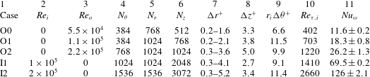
Reference Ostilla-Mónico, Verzicco, Grossmann and Lohse2016). The computational domain was uniformly discretized in the azimuthal and axial directions, while a clipped Chebyshev-type clustering was used in the radial direction. Full details of the numerical resolution used are provided in table 1. The table includes pure ICR data (i.e. the I1 and I2 cases) from Ostilla-Mónico et al. (Reference Ostilla-Mónico, Verzicco, Grossmann and Lohse2016) (referred to there as R1 and R2) for comparison. The I1 case has the same
 $Re_{{\it\tau}}$
as the O2 case, while the I2 case has the same driving shear as the O2 case.
Details of the numerical simulations. Column 1 is the name by which the simulation will be referred to in the article. Columns 2 and 3 are the inner and outer cylinder Reynolds numbers. Columns 4–6 represent the numbers of points in the azimuthal, radial and axial directions. Column 7 shows the minimum and maximum resolutions in the radial direction normalized with the inner cylinder wall unit. Columns 8 and 9 show the axial and azimuthal resolutions (at the inner cylinder) in inner cylinder wall units. Column 10 refers to the inner cylinder frictional Reynolds number, and the last column shows the torque non-dimensionalized as a pseudo-Nusselt number.

3 Results
We first focus on the torque to drive the cylinders. At comparable Reynolds numbers, a smaller torque is required for pure OCR than for pure ICR, as can be seen from table 1. The torque, non-dimensionalized as a pseudo-Nusselt number
 $Nu_{{\it\omega}}=J^{{\it\omega}}/J_{pa}^{{\it\omega}}$
, where
 $J_{pa}^{{\it\omega}}$
is
 $J^{{\it\omega}}$
for the purely azimuthal flow, is approximately a factor four smaller. As a direct consequence of this, the frictional Reynolds number
 $Re_{{\it\tau}}$
is approximately a factor two lower because
 $Re_{{\it\tau}}\sim \sqrt{Nu_{{\it\omega}}}$
. This results in smaller values of
 $u_{{\it\tau}}$
for pure OCR, and thus the longer transients observed in the DNS.
Transport of angular velocity from across the gap is much more inefficient in the case of subcritical turbulence, something that can be expected from the ‘optimal’ transport results of van Gils et al. (Reference van Gils, Huisman, Grossmann, Sun and Lohse2012) and Paoletti et al. (Reference Paoletti, van Gils, Dubrulle, Sun, Lohse and Lathrop2012), where the driving torque drastically decreases with the appearance of the radial partitioning into subcritical and supercritical zones. However, unlike the quasi-Keplerian case, where
 $|r_{o}^{2}{\it\omega}_{o}|>|r_{i}^{2}{\it\omega}_{i}|$
and
 $|{\it\omega}_{o}|<|{\it\omega}_{i}|$
, which were found both numerically (Ostilla-Monico et al.
Reference Ostilla-Monico, Verzicco, Grossmann and Lohse2014b
) and experimentally (Nordsiek et al.
Reference Nordsiek, Huisman, van der Veen, Sun, Lohse and Lathrop2015) to not sustain angular velocity transport across the gap, in pure OCR there is still turbulence present, and the flow is not purely azimuthal because
 $Nu_{{\it\omega}}\neq 1$
. In the case of pure OCR rotation, the gradients of both angular velocity and angular momentum point in the same direction, i.e. inwards, while in the quasi-Keplerian cases, they point in different directions, i.e. inwards for the angular momentum and outwards for the angular velocity.
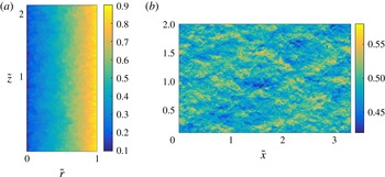
To understand why the torque is lower for pure OCR, we visualize the flow field in figure 1, which shows a pseudocolour plot of the instantaneous angular velocity for an azimuthal cut (a) and at the mid-gap (b) for the O2 case. A complete absence of the large-scale rolls can be seen. These figures can be compared to figures 1 and 3 of Ostilla-Mónico et al. (Reference Ostilla-Mónico, Verzicco and Lohse2015), visualizations of the instantaneous velocities for the I1 case. For the same geometrical parameters, and similar Reynolds numbers, the velocities in the pure IRC cases have marked axial inhomogeneities. The existence of rolls has been linked to increased transport (Brauckmann & Eckhardt Reference Brauckmann and Eckhardt2013; Grossmann et al.
Reference Grossmann, Lohse and Sun2016), so from this alone we can expect a smaller
 $Nu_{{\it\omega}}$
.
Pseudocolour plot of the instantaneous angular velocity for the O2 case for a constant azimuth (a) and at the mid-gap (b). No large-scale structures can be seen, as is seen for pure inner cylinder rotation in Ostilla-Mónico et al. (Reference Ostilla-Mónico, Verzicco and Lohse2015, Reference Ostilla-Mónico, Verzicco, Grossmann and Lohse2016).

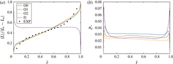
Figure 2(a) shows
 $\tilde{L}$
, the azimuthally, temporally and axially averaged angular momentum for the O0, O1, O2 and I1 cases, as well as the experimental data from Burin & Czarnocki (Reference Burin and Czarnocki2012) for
 ${\it\eta}=0.97$
and
 $Re_{o}=6800$
. For pure ICR, rolls effectively redistribute angular momentum such that the flow is marginally stable. This is reflected in the I1 case showing a constant angular momentum profile in the bulk equal to the arithmetic average of
 $L$
at both cylinders. For pure OCR, the flow is already stable and thus we do not expect rolls to form or angular momentum to be redistributed. Instead, all pure OCR cases show a significant gradient of angular momentum in the bulk. For pure OCR, the larger the angular momentum gradient in the bulk, the more stable the configuration. The resulting profile shape comes from the competing mechanisms of centrifugal stabilization in the bulk and destabilization in the boundary layers by shear. The numerical pure OCR velocity profiles are in qualitative agreement with the experimental profiles, as the bulk profile becomes flatter and the boundary layers thinner with increasing
 $Re_{o}$
. We also note that similar phenomena were seen for the strongly counter-rotating cylinder cases of Brauckmann, Salewski & Eckhardt (Reference Brauckmann, Salewski and Eckhardt2016), which show significant deviations from constant angular momentum profiles in the bulk after the onset of the radial partitioning of stability.
(a) The temporally, axially and azimuthally averaged angular momentum for the three pure OCR cases and the I1 case for comparison, as well as experimental data from Burin & Czarnocki (Reference Burin and Czarnocki2012). (b) The root mean square (r.m.s.) of the azimuthal velocity for the numerical cases.

Figure 2(b) shows the root mean square (r.m.s.) of the azimuthal velocity
 $u_{{\it\theta}}^{\prime }$
for the O0, O1, O2 and I1 cases. The level of fluctuations decreases with Reynolds number. When comparing the O1 and the I1 cases, a much lower level of fluctuations inside the boundary layer is seen for pure OCR. This is expected from the much lower values of
 $u_{{\it\tau}}$
for pure OCR than for pure ICR. Indeed,
 $u_{{\it\tau}}$
is approximately a factor of two larger for the I1 case, and this is directly reflected in the level of fluctuations being approximately twice as large as for the O1 case.
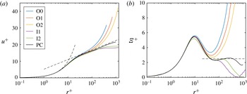
(a) The streamwise velocity in inner cylinder wall units for all the cases at the inner cylinder, and from PC flow at
 $Re_{{\it\tau}}\approx 1000$
. The dashed curve represents
 $u^{+}=r^{+}$
and the dashed line represents
 $u^{+}=2.5\log (r^{+})+5.2$
. (b) The logarithmic diagnostic function for the cases shown in (a). The horizontal dashed line represents
 ${\it\Xi}^{+}=2.5$
.

We now focus on the near-wall region, to compare pure OCR with pure ICR, and to quantify the effects of curvature and instability. Figure 3(a) shows the mean streamwise velocity at the inner cylinder region in inner units for all cases, where
 $U^{+}$
is
 $U^{+}=(r_{i}{\it\omega}_{i}-\langle u_{{\it\theta}}\rangle _{{\it\theta},z,t})/u_{{\it\tau},i}$
and
 $r^{+}$
is the distance from the wall in inner cylinder wall units,
 $r^{+}=(r-r_{i})/{\it\delta}_{{\it\nu},i}$
. The simulation of plane Couette (PC) flow at
 $Re_{{\it\tau}}\approx 1000$
from Pirozzoli, Bernardini & Orlandi (Reference Pirozzoli, Bernardini and Orlandi2014) has been added for comparison. Rotating PC flow is the limit of TC flow when
 ${\it\eta}\rightarrow 1$
, i.e. the two cylinders become two plates. Therefore, curvature effects and centrifugal (de)stabilization are not present. Romanov (Reference Romanov1973) showed that PC flow is also stable to linear perturbations at all Reynolds numbers, though the mechanism is not centrifugal and this could cause different behaviour.
Both pure ICR and pure OCR TC flow can be seen to deviate substantially from the classical von Karman law of the wall,
 $U^{+}={\it\kappa}^{-1}\log (y^{+})+B$
, with
 ${\it\kappa}=0.4$
and
 $B=5.2$
, while PC flow follows it better. Pure OCR TC flow has a significantly higher value of
 $U^{+}$
far away from the walls, while pure ICR TC flow has a rather flat profile in the bulk – consistent with the notion that angular momentum is redistributed in the bulk. It seems that while, in the bulk, pure ICR redistributes angular momentum through the rolls, pure OCR has the opposite effect, and generates a strong gradient of angular momentum. Thus, the two lines deviate from the PC profile in opposite ways, showing the importance of the centrifugal (in)stability.
Very close to the wall, it could seem that the O2 case is beginning to show a logarithmic-like region. This can be better seen in figure 3(b), which shows the logarithmic diagnostic function
 ${\it\Xi}^{+}=\text{d}U^{+}/\text{d}(\log r^{+})$
for the same cases. Even if the pure OCR cases deviate much more than both the PC cases and the pure ICR cases, and do not show the S-like shape in
 ${\it\Xi}^{+}$
around
 $r^{+}\approx 100$
that is seen in several canonical flows (Ostilla-Mónico et al.
Reference Ostilla-Mónico, Verzicco, Grossmann and Lohse2016), they are coming closer to the classical law of the wall with increasing
 $Re_{{\it\tau}}$
number. It could be that for higher drivings, and thus higher
 $Re_{{\it\tau}}$
, the pure OCR profiles collapse in the near-wall region onto the PC profiles, once the boundary layer is small enough such that it no longer feels the effect of curvature and of the centrifugal stabilization. However, from the figures its seems that the centrifugal (in)stability mechanism plays a critical role in determining the bulk behaviour, and is responsible for the large deviations of TC flow from PC flow behaviour. Finally, the outer cylinder wall profiles show very similar behaviour and are not shown here, so the main effects seems to be mediated by the centrifugal (in)stability and not by convex or concave curvature.
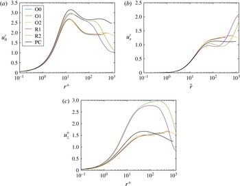
Root-mean-squared fluctuations for all cases for the streamwise/azimuthal (a), wall-normal/radial (b) and spanwise/axial (c) velocities in inner cylinder wall units.

We now show the fluctuations in inner cylinder wall units for all three components of velocity in figure 4. While the streamwise fluctuations are considerably smaller for pure OCR, the profiles are closer to those of plane Couette flow for radial (wall-normal) and axial (spanwise) fluctuations. The cases of pure ICR rotation show very strong deviations for these two velocities, attributed to the axial inhomogeneity of the flow in Ostilla-Mónico et al. (Reference Ostilla-Mónico, Verzicco, Grossmann and Lohse2016). Again, the outer cylinder wall profiles show very similar behaviour and are not shown here. The significant deviations from PC flow behaviour can be attributed again to the different mechanisms at play, especially centrifugal (de)stabilization.
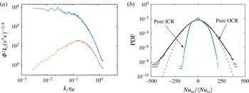
Finally, to quantify the nature of transport in the boundary layers, figure 5(a) shows the pre-multiplied axial spectra of radial and azimuthal velocity for the O2 case at
 $r^{+}\approx 12$
, i.e. around the peak of
 $u^{\prime }$
fluctuations inside the boundary layer. The peak seen at the roll-wavelength for pure ICR in Ostilla-Mónico et al. (Reference Ostilla-Mónico, Verzicco, Grossmann and Lohse2016) is no longer present, as transport occurs through small-scale fluctuations or ‘bursts’ (Brauckmann & Eckhardt Reference Brauckmann and Eckhardt2013). These bursts transport angular velocity, and are very intermittent, having large amplitude but slow dynamics, meaning that extreme events are more likely to happen. The peak in the radial spectra corresponds to the characteristic length scale of these bursts. We note that spectra seen here are consistent with the spectra seen in channel flow (Jimenez Reference Jimenez2012) and in plane Couette flow (Avsarkisov et al.
Reference Avsarkisov, Hoyas, Oberlack and García-Galache2014), having a peak in the radial (wall-normal) spectra associated with the size of the transporting structures, and no saturation for the azimuthal velocity, indicating large-scale structures attached to the wall that do not transport Reynolds stresses.
To quantify this feature, figure 5(b) shows the probability density function (p.d.f.) of the local convective angular velocity current
 $u_{r}{\it\omega}\approx Nu_{{\it\omega}}$
for both the O2 and I2 cases at mid-gap, i.e. in the bulk, as well as a Gaussian distribution with mean and variance equal to the O2 case. While for pure ICR, transport occurs mainly through the hairpin vortices, seen as the prominent peak centred around the middle of the graph, for the O2 case, the signature of these bursts is reflected here in the fatter tails of the p.d.f., which are super-Gaussian, and have no apparent power-law behaviour. The p.d.f.s are not symmetric around zero, as there is a net positive angular velocity transport. From both panels, it becomes clear that the mechanisms for angular velocity transport are very different for pure ICR and pure OCR.
(a) The axial spectra for the radial (red dashed) and azimuthal (blue solid) velocities for
 $r^{+}\approx 12$
, near the inner cylinder, for the O2 case. (b) The p.d.f. of
 $Nu_{{\it\omega}}$
at the mid-gap for both the I2 and O2 cases. The orange dashed line represents a Gaussian p.d.f. with mean and variance equal to those of the O2 case.

4 Summary and conclusions
A series of DNS of turbulent Taylor–Couette flow with pure outer cylinder rotation were conducted. Overall, pure OCR TC flow behaves in a very different manner from supercritical pure ICR TC flow. The torque and fluctuation levels are much smaller for comparable Reynolds numbers than those of pure ICR flow. Transport of angular velocity, now more inefficient, occurs through intermittent ‘bursts’ instead of through the large-scale structures. Pure OCR TC flow can be seen as just an extreme case of counter-rotating TC flow with the radial partitioning of stability described by Brauckmann & Eckhardt (Reference Brauckmann and Eckhardt2013) and Brauckmann et al. (Reference Brauckmann, Salewski and Eckhardt2016) moving to the inner cylinder. The competition between the shear instabilities in the boundary layer and the centrifugal stabilization in the bulk gives rise to mean velocity profiles that show a significant angular momentum gradient in the bulk, consistent with the experiments of Burin & Czarnocki (Reference Burin and Czarnocki2012). The near-wall profiles deviate very strongly from both pure ICR rotation and plane Couette flow, revealing the very strong role of the centrifugal mechanisms in TC flow, be it stabilizing for pure OCR or destabilizing for pure ICR. Pure ICR and pure OCR deviate in opposite manners from the PC flow profiles, so this can be attributed to the role of centrifugal (de)stabilization. Finally, the large-scale structures completely disappear in this regime, and the axial velocity spectra reveal that transport near the wall occurs predominantly through very intermittent and small-scale structures.
Two main questions remain: the large-scale rolls seem to form in certain regions of the parameter space, where the flow is fully unstable (Ostilla-Monico et al.
Reference Ostilla-Monico, van der Poel, Verzicco, Grossmann and Lohse2014a
). However, it is still unclear why these rolls are formed, and why they are axially pinned. From these simulations, it seems that the centrifugal instability plays a clear role in the nature of the turbulence and the formation of the rolls, but a complete understanding is still missing. Furthermore, the question remains of what happens in the quasi-Keplerian regime, which satisfies
 $|L_{o}|>|L_{i}|$
and
 $|{\it\omega}_{o}|<|{\it\omega}_{i}|$
(Ostilla-Monico et al.
Reference Ostilla-Monico, Verzicco, Grossmann and Lohse2014b
; Nordsiek et al.
Reference Nordsiek, Huisman, van der Veen, Sun, Lohse and Lathrop2015). The simulations in this article have generated and sustained turbulence in the absence of end plates at high Reynolds numbers. However, turbulence in the quasi-Keplerian regime has not been sustained in simulations, and, as mentioned previously, this could be due to the opposing gradients of angular momentum and angular velocity. We refer the reader to Grossmann et al. (Reference Grossmann, Lohse and Sun2016) for a recent review of the progress on this problem.
Acknowledgements
We thank V. Spandan for extensive help in proof-reading the paper and keeping some simulations running during the months-long wall-clock times, and we thank M. Burin for providing the data for figure 2 and for valuable discussions. We acknowledge Y. Yang and X. Zhu for fruitful and stimulating discussions. We also gratefully acknowledge computational time for the simulations provided by SurfSARA on resource Cartesius through a NWO grant.