I. INTRODUCTION
As a relatively new class of porous materials, carbon foams have been intensively studied since it was initially prepared by the pyrolysis of thermosetting polymer in 1960s,Reference Ford1,Reference Googin, Napier and Scrivner2 and it is widely used for a variety of applications, including catalyst support, heat exchanger, high temperature isolation, gas separation, filter for molten metal and corrosive chemicals, light-weight structural part, fuel cell electrode, and template to prepare ceramic and metal foams.Reference Gallego and Klett3–Reference Mehtaa, Andersonb and Hagerc5 In particular, applications including catalyst support, filter, and template need satisfactory filterability, which can be dominantly modified by the void in cell walls. An interconnected porous structure is thus crucial, and a facile approach to carbon foams with appropriate voids is pursued.
Carbon foams have been prepared by foaming and carbonization from various precursors. Generally, synthetic polymeric materials such as phenol formaldehyde, resorcinol formaldehyde, poly urethane, furfural resin, polyvinylidene chloride, and polyacrylonitrileReference Mukai, Tamitsuji, Nishihara and Tamon6–Reference Inagaki, Morishita, Kuno, Kito, Hirano, Suwa and Kusakawa9 tend to be used for fabricating non-graphitic foams, whereas coal, coal tar pitch, and petroleum pitch are usedReference Klett, Mcmillan, Gallego and Walls10,Reference Li, Wang, An and Wang11 for graphitic foams. These precursors produce carbon foams with high carbon yield. However, because of a fast depleting rate of petroleum, the usage of renewable molecules of agricultural origin rather than the above petroleum-derived materials as precursors is getting momentum. Sucrose has been identified as an important renewable precursor candidate, and carbon foams derived from sucrose have been prepared for various usages.Reference Ryoo, Joo, Kruk and Jaroniec12–Reference Armandi, Bonelli, Geobaldo and Garrone16 In 2005, Böhme et al.Reference Böhme, Einicke and Klepel17 prepared mesoporous carbon foams from sucrose using a silica template. Lately, Prabhakaran et al. fabricated carbon foams by thermo-foaming from sucrose resinReference Prabhakaran, Singh, Gokhale and Sharma18,Reference Narasimman and Prabhakaran19 and sucrose melt.Reference Narasimman and Prabhakaran20 These studies reveal the feasibility of carbon foam preparation from sucrose.
Recently, the study of introducing clay and clay mineral to carbon foams to modify the mechanical and thermal properties attracts much attention. Wang et al.Reference Wang, Zhong, Wang and Yu21 added montmorillonite to mesophase pitch–based carbon foams and achieved improved strength and markedly decreased thermal conductivity. Wu et al.Reference Wu, Liu, Fang, Mei and Luo22,Reference Wu, Fang, Mei and Luo23 reported that carbon foams with aluminosilicate showed better compressive strength and oxidation resistance than that of pure foams. Kaolinite (Al2Si2O5(OH)4) is a layered silicate mineral, with one tetrahedral sheet linked through oxygen atoms to one octahedral sheet of alumina octahedral. This clay mineral, with crystal habit of thin pseudohexagonal plates or stacked clusters of plates and exposed cationic/anionic edges/surfaces, is expected to contribute stabilizing effect on bubbles in a “clay–water–precursor” ternary system by coulombic interaction. In this study, particular attention is given to prepare carbon foams starting from sucrose with kaolinite clay as additive. The clay mineral product distribution, phase composition, pore structure, and compressive strength of the carbon foams were characterized.
II. EXPERIMENTAL
A. Fabrication of carbon foams
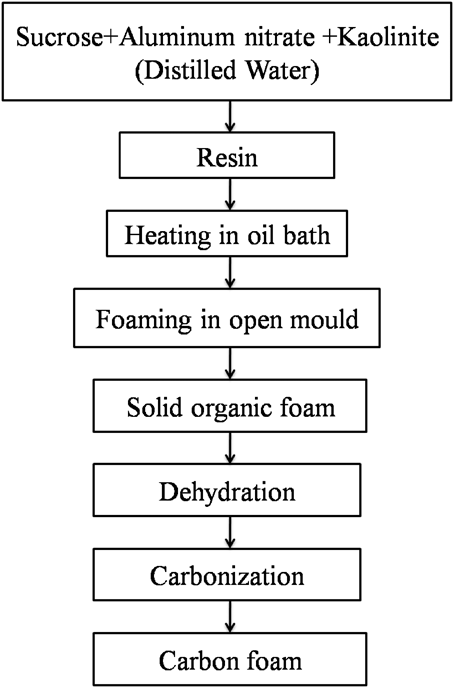
Sucrose, kaolinite, and aluminum nitrate (Al(NO3)3·9H2O) (AR, Sinopharm Chemical Reagent Co., Ltd., Beijing, China) were used as the precursor of carbon foam, the additive, and the blowing agent, respectively. To investigate the effect of clay mineral addition on the phase, microstructure, and mechanical properties, 0, 5, 10, and 15 wt% kaolinite of sucrose were introduced to form samples S1, S2, S3, and S4, respectively. Sucrose, aluminum nitrate (2 wt% of sucrose), and kaolinite were weighed and thoroughly mixed in an agate mortar by hand. Silicone oil was used as the heating medium, held in a beaker, and heated to ∼180 °C by an electric heating platform. The mixtures were held in another smaller beaker and appropriate distilled water was added in to form a suspension resin. The beaker containing the resin was then submerged in the silicone oil. Soon afterward, the sucrose got melt and the resin changed gradually from white to pale-yellow, accompanied with slow bubbling. When the resin totally became yellow, the beaker was transferred to a preheated air oven at 120 °C. The samples undergo thermo-foaming therein overnight, subsequent setting into consolidated solid green foams, which were followed by dehydration (5 °C/min up to 150 °C, 1 °C/min from 150 to 250 °C, and then holding for 20 h in air) and carbonization (5 °C/min up to 250 °C, 2 °C/min from 250 to 1200 °C, holding for 2 h and then naturally cooled to room temperature in a chamber furnace by buried coke under reducing atmosphere). The flow chart of the preparation procedure is illustrated in Fig. 1.
Flow chart for the preparation of carbon foam from sucrose with kaolinite addition.

B. Characterization
The powder diffraction pattern of carbon foams was recorded by x-ray powder diffraction (XRD; Cu target, Kα1 radiation, λ = 1.5406 Å; Rigaku Corporation, Tokyo, Japan) with a step of 0.02° (2θ) and a scanning rate of 8° min−1. The microstructures were observed by scanning electron microscopy (SEM; JEM-6460LV, Tokyo, Japan) equipped with an energy dispersive spectroscopy detector (EDS; OXFORD INCA X-Sight, Oxford, UK), before which the samples were coated with gold to improve conzductivity. Bulk density of the carbon foams was calculated from dimensional measurements. The as-prepared specimens were machined by a knife to blocks of 25 × 25 × 12 mm3 (digital pictures shown in Fig. 2) for compressive strength measurement according to ASTM Standard C365/C365M-05. The tests were carried out on an electron universal testing machine (CMT-5504; New Three Points Corporation, Shenzhen, China) with a displacement rate of 0.5 mm/min at room temperature. The compressive yield strength (σ) and strain (ε) was calculated by
 $${\rm{\sigma }} = {F \mathord{\left/ {\vphantom {F A}} \right. \kern-\nulldelimiterspace} A}\quad ,$$
 $${\rm{\varepsilon }} = {{\Delta l} \mathord{\left/ {\vphantom {{\Delta l} {{l_0}}}} \right. \kern-\nulldelimiterspace} {{l_0}}}\quad ,$$
where σ is the compressive yield strength (MPa), F is the load (N) at yield, A is the cross-sectional area (mm2), ε is the strain, l 0 is the specimen original length (mm), and Δl is the specimen displacement (mm).
Digital pictures of carbon foams with different kaolinite additions heated at 1200 °C for 2 h. The samples were machined to standard dimensions for compressive strength test.
III. RESULTS AND DISCUSSION
A. Phase composition and clay product distribution
The preparation of carbon foams from aqueous acidic sucrose solution and molten sucrose, with HNO3 and Al(NO3)3 as blowing agents, has been reported earlierReference Prabhakaran, Singh, Gokhale and Sharma18–Reference Narasimman and Prabhakaran20; in this study, the previous fabrication route is modified as aforementioned to guarantee a relatively high viscosity and a gentle temperature rising of the resin on heating. The relatively high viscosity is expected to ensure that the kaolinite clay gets evenly distributed therein without unexpected sedimentation.
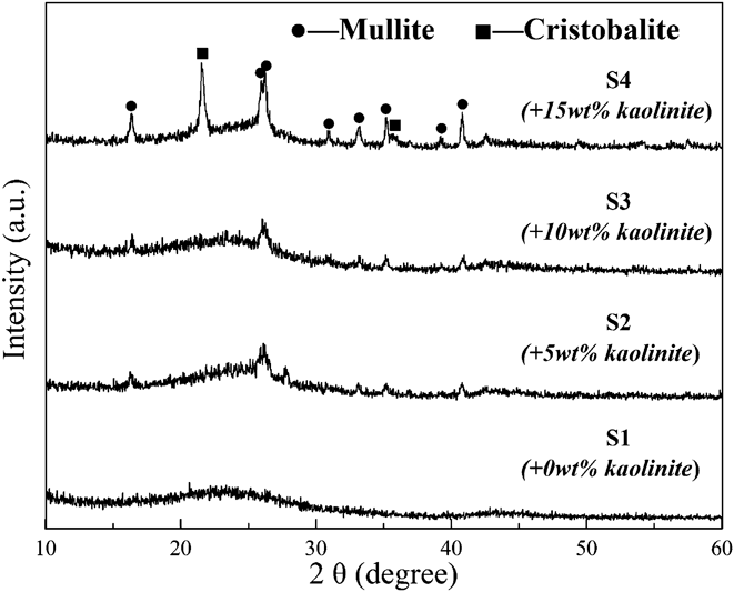
XRD patterns of the carbon foams are shown in Fig. 3. The sharp diffraction peaks indicate phases of mullite and cristobalite. On heating, first, the absorption water on the clay was evaporated [Reaction (3)] in setting and dehydration; then the molecule water in the crystal structure got removed; and it finally transformed into mullite and cristobalite according to Reaction (4) in carbonization.Reference Sanz, Madani and Serratosa24 The board peaks at 2θ value range of 22–28 and 42–47 corresponding to the semicrystalline reflections from (002) and (101) planes of graphiteReference Klett, Hardy, Romine, Walls and Burchell25 reveal the glassy phase carbon. With an increasing amount of kaolinite, the diffraction peak intensity of mullite and cristobalite got gradually enhanced. Considering that the powder samples for XRD characterization are randomly selected, the evolution of diffraction peak intensity reveals the even distribution of clay product in the carbon foams.
 $$\left( {{\rm{A}}{{\rm{l}}_{\rm{2}}}{\rm{S}}{{\rm{i}}_{\rm{2}}}{{\rm{O}}_{\rm{5}}}{{\left( {{\rm{OH}}} \right)}_4}} \right)x{{\rm{H}}_2}{\rm{O}} \to {\rm{A}}{{\rm{l}}_2}{\rm{S}}{{\rm{i}}_2}{{\rm{O}}_5}{\left( {{\rm{OH}}} \right)_4} + x{{\rm{H}}_2}{\rm{O}}\quad {\rm{,}}$$
 $${\rm{A}}{{\rm{l}}_2}{\rm{S}}{{\rm{i}}_2}{{\rm{O}}_5}{\left( {{\rm{OH}}} \right)_4}\left( {{\rm{Kaolinite}}} \right) \to {\rm{A}}{{\rm{l}}_6}{\rm{S}}{{\rm{i}}_2}{{\rm{O}}_{13}}\left( {{\rm{Mullite}}} \right) + {\rm{Si}}{{\rm{O}}_2}\left( {{\rm{Cristobalite}}} \right) + {{\rm{H}}_2}{\rm{O}}$$
XRD patterns of samples S1–S4 sintered at 1200 °C for 2 h, suggesting phases of mullite, cristobalite, and glassy phase carbon.
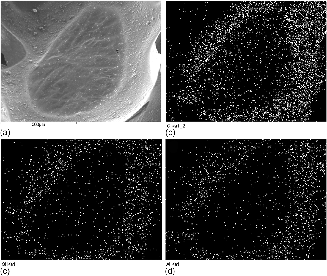
To further investigate the distribution of kaolinite product in the carbon foams, elemental mapping of microstructures by EDS, which provides in addition to the SEM image a picture of the element distribution of a surface, is conducted on both a cell and a strut of the carbon foams. Figure 4 shows the SEM image of a closed cell membrane and the corresponding elemental mapping result of C, Si, and Al. In Fig. 4(a), the thin cell membrane exists in the cell wall; microsize particles grow on both the membrane and the cell wall like humps. The EDS mapping image of C outlines an oval shape, and the mapping of Si and Al provides a similar distribution image. This consistency suggests the mineral product (containing Si and Al elements) has a relatively even distribution in the carbon cell wall matrix.
SEM image of a cell membrane in the cell wall (a), and the corresponding element mapping results: carbon, C (b); silicon, Si (c); and aluminum, Al (d).
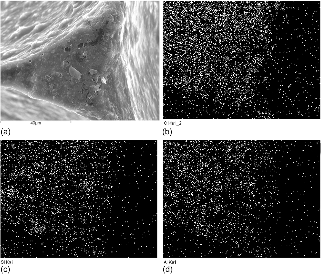
In addition to the cell wall, further consistency was observed in the cell strut matrix, as shown in Fig. 5. The similarity of C and the mapping image of Al and Si in the strut indicates that the strut contains the mineral product; moreover, compared with the element mapping of the cell wall (Fig. 4) where the intensity of Si and Al is apparently weaker than that of C, the intensity of Si and Al here in the strut is much more closer to that of C, suggesting that the kaolinite prefers to be concentrated in the strut than in the cell wall. During the growth of bubbles, high shearing force exists in cell walls while in the junction the stress is minimal, which results in the clay mineral products being mainly restrictively distributed in the strut.
SEM image of a cell strut (a), and the corresponding element mapping results: carbon, C (b); silicon, Si (c); and aluminum, Al (d).
B. Microstructure of carbon foams
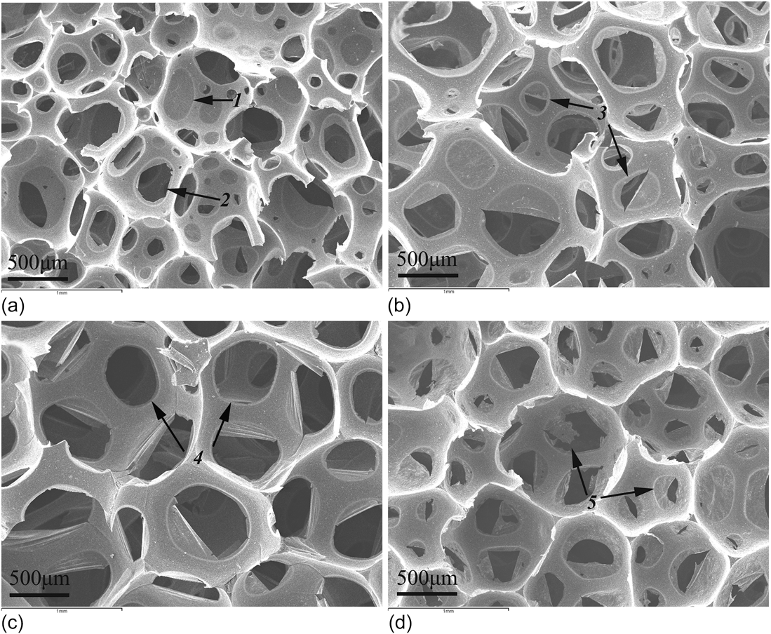
The typical SEM images of carbon foam samples S1–S4 with various kaolinite additions carbonized at 1200 °C are shown in Fig. 6. Microstructure of the foams consists of spherical cells of size in the range of 400–1000 μm. Competitive growth and surface tension are known to be dominating factors that shape the foams with spherical cells.Reference Wang, Luo and Ni26 In Fig. 6, both closed cells with complete membrane (signed with arrow 1) and open interconnected cells with circular or oval shape voids (signed with arrow 2) were observed. Moreover, the voids consist of two types: one is smooth and the other is rough (arrows 3 and 5). The smooth ones (pointed out with arrow 4) form from the blowing agent–induced air bubbles during foaming when the resin is fluid, whereas the rough type generates by brittle fracture of cell walls after the hardening of sucrose molecules.Reference Klett, Hardy, Romine, Walls and Burchell25,Reference He, Tang, Zhu and Yang27 This fracture seems to occur during later stages of foaming after setting or during dehydration and carbonization.Reference Klett, Hardy, Romine, Walls and Burchell25 A more detailed study on the thermo-foaming process of molten sucrose by Narasimman and PrabhakaranReference Narasimman and Prabhakaran20 has verified the gas bubble generation due to water vapor, O2, and NOx gases, which are produced by acid-catalyzed condensation between sucrose hydroxyl groups and by thermal decomposition of Al(NO3)3·9H2O, respectively. The formation of pores connecting the cells is explained as follows: after the foaming of molten sucrose, the vapor and gases are continually produced inside the bubbles, which increase the pressure inside the bubbles; the voids connecting the cells are thus created by the rupture of cell walls when the pressure difference exceeds the strength of cell walls. It is known that sucrose contains 42.1% carbon content and shrinkage would occur along with the post-foaming heat treatments,Reference Narasimman and Prabhakaran20 resulting in broken membrane. The two processes contribute to form the different cell openings. Moreover, as can be seen, compared with Figs. 6(a) and 6(d), Figs. 6(b) and 6(c) reveal more cell openings in cell walls.
SEM images of carbon foams with 0 wt% (a), 5 wt% (b), 10 wt% (c), and 15 wt% (d) of kaolinite.
In samples S2–S4 added with kaolinite [Figs. 6(b)–6(d)], improved uniformity of the cells was observed, suggesting that the clay additive helped stabilize the bubbling of thermal foaming. It is reportedReference Narasimman and Prabhakaran19 that the particles with suitable wetting characteristics preferentially adhere to the air–water interface, and particles have been used as a strategy to stabilize bubbles against coalescence and foam drainage. In the presence of kaolinite, physically adhesion of the vapor and gases to the clay edges/surfaces could happen, a process helping the bubbles against coalescence or rupture and thus resulting in a better structure uniformity. The previous studyReference Narasimman and Prabhakaran19 on thermo-foaming of activated carbon powder dispersions in an aqueous sucrose resin also confirms that the activated carbon particles adsorbed on the gas–liquid interface help stabilize the gas bubbles and result in foaming of the poorly cross-linked sucrose polymer resin of low viscosity.
C. Compressive strength of carbon foams
The compressive stress–strain curves of carbon foams with different amount of kaolinite were investigated, as shown in Fig. 7. Under compressive loading, the observed multistage deformation response of the carbon foams consists of a linear elastic loading section, a plateau region, and the failure.Reference Wang, Luo and Ni26,Reference Shen and Nutt28 Samples S1 and S4 exhibited similar compressive stress–strain curves, whereas those of S2 and S3 were alike. The peak value of the plateau region, which comes after the end of the elastic threshold, denotes the crack initiation pointReference Shen and Nutt28; thus, the initial crack in S2 and S3 occurs earlier than that in S1 and S4. The ultimate calculated compressive strengths of the carbon foams were ranging from 0.08 to 0.21 MPa, which initially dropped and then increased when the amount of kaolinite were 0, 5, 10, and 15 wt%, respectively. The apparent density (mass divided by volume) was measured to be 0.072–0.108 g/cm3. The introduction of kaolinite in the present sucrose-based carbon foams induces a decreased compressive strength, which is not in keeping with the related study starting from mesophase pitch and phenolic resin.Reference Wang, Zhong, Wang and Yu21,Reference Wu, Liu, Fang, Mei and Luo22 A main reason for this inconsistency may be the difference in the precursor used. The distinguished feature of the present carbon foams is the abundant interconnected void existing in the thin cell walls. It is noted in Fig. 6 that the foams with 5 and 10 wt% kaolinite addition (samples S2 and S3) exhibit more voids in cell walls, in comparison with those in S1 and S4. The evolution of the voids, first increasing and then decreasing, is in agreement with that of the compressive strength.
The compressive strength versus strain of carbon foams with different kaolinite additions.
Moreover, the compressive strength of porous structure is also known to be depending much on the pores (such as pore size and pore amount) and cracks.Reference Voigt, Storm, Abendroth, Aneziris, Kuna and Hubaálková29,Reference Seeber, Gonzenbach and Gauckler30 Compared with the coal and pitches, carbon foams derived from sucrose, which contains 42.1 wt% carbon, exhibit low density because of the relatively low carbon yield; the solid organic foam undergoes large shrinkage during carbonization that would induce warping or cracking. Thus, in addition to the differences in voids (Fig. 6), observations of cell walls at higher magnitude reveal a distinct difference of the cracks surrounding the voids in S1–S4, as illustrated in Fig. 8. In all samples, dense struts were obtained [Fig. 8(a1)]. Voids resulting from air bubbling in S1 [Fig. 8(a2)] show rare microcracking; however, in S2 and S3 some cracks are found and highlighted [Figs. 8(a)–8(c)]. Under compressive loading, the cracks around the voids could be the origin of many newly generated cracks and catalyze their propagation, which eventually decreases the ultimate compressive strength. Moreover, in S4, much less cracks exist in cell walls [Fig. 8(d)]. The evolution of microcracks in S0–S4, which sensitizes the fracture of the porous samples under compressing, also contributes to the results of compressive strength tests.
SEM images of carbon foams with 0 wt% (a), 5 wt% (b), 10 wt% (c), and 15 wt% (d) of kaolinite, in which the microcracking around the voids was highlighted.
IV. CONCLUSION
Carbon foams have been fabricated by thermo-foaming from sucrose and kaolinite clay mineral using aluminum nitrate as the blowing agent. Phases of the carbon foams consist of mullite, cristobalite, and glassy carbon. The as-fabricated carbon foams have dense struts and spherical open cells with complete cell membrane and incomplete interconnected voids. The voids consist of both smooth and coarse ones. The introduction of kaolinite helps improve the structure uniformity of the carbon foams. Elemental mapping shows that the mineral product is more concentrated on the strut and cell walls. With an increasing amount of kaolinite, the compressive strength of carbon foams initially decreases and then increases. The ultimate compressive strength evolution is found to be in correlation with the amount of voids and the microcracking in the carbon foams.
ACKNOWLEDGMENTS
This work was financially supported by the National Natural Science Foundation of China (Grant No. 51032007) and the Research Fund for the Doctoral Program of Higher Education of China (Grant No. 20130022110006). The authors also thank the anonymous reviewers for the valuable discussion. Y.G. Liu thanks the Program for New Century Excellent Talent supporting project (Grant No. NCET-12-0951); K. Chen thanks the Fundamental Research Funds for the Central Universities (Grant No. 2652013040).