I. INTRODUCTION
Magnesium alloys have gradually been utilized for lightweight structural and functional parts in aircrafts, automotive applications, electronics, and other industry fields, due to the corresponding high specific strength, light specific weight, high damping capacity, recyclability, and electromagnetic shocks shielding ability. Reference Pekguleryuz and Celikin1 In contrast, local damage inevitably occurs at the magnesium equipment surfaces such as cracks, abrasion, and corrosion. These impairments seriously affect the service life and quality of these components. The overall replacement of damaged equipment caused a huge increase in costs. For this reason, it is proven necessary for the damaged parts to be repaired by utilization of suitable methods. The surfacing welding is the common repairing technology and has been widely utilized in the industrial equipment manufacturing, maintenance, and repairs. Reference Hu, Wang, Li and Ding2,Reference Meng and Zhang3 Generally, the properties of surfacing welding alloys, such as wear and corrosion resistance, have an important effect on the whole performance and life of the repaired magnesium components.
The wear constitutes a serious problem in a high number of engineering applications such as bearings, moving parts, and engine parts. Although it is only a surface phenomenon, it might completely undermine the mechanical function of engineering parts and cause a structural failure directly or as part of an effects combination. Reference Sharma, Anand and Krisha4 For the wear resistance improvement of the surfacing magnesium alloys, the heat treatment is one of the well-known methods for the expectations to be achieved. The heat treatment can affect wear through changes in the species and amounts of the reinforcing phase, along with the nature of the interface between the reinforcement and the matrix. As one of the widely utilized magnesium alloys, the AZ91 alloy usually contains high quantities of the β-phase (Mg17Al12), distributed along the grain boundaries. The microstructure, the morphology, and the volume fraction of the β-phase could be changed by both solid solution and aging treatment, which could prominently affect the wear resistance. Certain works have been made for the distribution and morphology investigation of the Mg17Al12 phase following heat treatment and the corresponding effects on the wear property of both as-cast and extruded AZ series alloys. Reference Celotto5,Reference Yan and Wang6 In contrast, only a low number of studies were focused on the wear resistance of surfacing welding magnesium alloys.
Therefore, in the current work, the tungsten inert gas (TIG) welding was applied for the surfacing of AZ91 magnesium alloys. The solid solution treatment followed by aging (T6) was adopted for the β-phase to be completely dissolved and consequently renew the corresponding precipitation. The wear behavior of the surfacing AZ91 alloy specimens and the eventual effects of T6 heat treatment on the wear resistance were investigated in detail. Specimens’ heat treated by the solid solution (T4) was also tested for the β-phase effects on the wear behavior to be better understood.
II. EXPERIMENTAL PROCEDURE
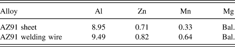
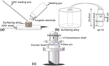
In this study, the commercial AZ91 magnesium alloy sheets of 10 mm in thickness were subjected to surfacing welding with the AZ91 welding wires of 3.0 mm in diameter. The chemical compositions of the AZ91 sheets and welding wires are summarized in Table I. Surfacing samples with a size of φ20 × 30 mm were prepared by the TIG welding. The surfacing welding diagram is presented in Fig. 1(a). Prior to welding, the oxide layer on the surface of the base metal was eradicated by mechanical polishing and the surface was subsequently cleaned with acetone and ethyl alcohol. The TIG welding conditions adopted during welding were the 130 A welding current, 15 V welding voltage, 0.8 mm/s welding speed, and shielding by pure argon (99.99%). The surfacing weld samples were subjected to solution treatment at 410 °C for 10 h and consequently quenched in water at room-temperature (T4). The samples that were solution-treated were aged at 200 °C for up to 20 h and cooled in the air (T6). The phase compositions of both as-received and heat treated specimens were determined by an X-ray diffractometer (XRD, MPDDY2094, PANalytical B.V., Almelo, the Netherlands) at a potential of 40 kV and a current of 40 mA. The data were refined by the Rietveld method Reference Rietveld7 and quantitative analysis was carried out to calculate the volume fraction of β-Mg17Al12. The metallographic samples were severed from the cross section of the surfacing weld samples, followed by mechanical polishing. The microstructures were observed by an optical microscope (OM, DMI5000M, Leica Microsystems, Wetzlar, Germany) and a field emission scanning electron microscope (FESEM, Zeiss Ultra Plus, Carl Zeiss Microscopy GmbH, Oberkochen, Germany). The macrohardness measurements were executed with a 452-SVD (Wolpert Wilson Instruments, Aachen, Germany) Vickers hardness tester, whereas each site was measured 4 times and consequently the average was received as the hardness value. The electrical conductivity of the alloys was examined by a SIGMASCOPE SMP10 (Helmut Fischer Technologie AG, Sindelfingen, Germany) conductivity tester.
Chemical compositions of welding wires and base sheet (mass fraction, %).

Schematic representation of (a) the surfacing welding, (b) the sampling location, and (c) the pin-on-disc experimental configuration.

Dry sliding wear tests without a lubricant were conducted by a pin-on-disk apparatus at an ambient temperature (∼25 °C). In order for the nonuniform structure zone to be avoided, the wear pins of 4.75 mm in diameter and 12.8 mm in length for wear testing were severed from the center area of the samples, as presented in Fig. 1(b). The wear resistance of the surfacing magnesium alloys was evaluated by a universal wear testing machine (MMD-1, Jinan Yihua Tribology Testing Technology Co. Ltd., Jinan, Shandong, China), whereas the wear loss was measured by an electronic analytical balance. The value for each condition was the average value of three samples. The experiments were performed under 5, 25, 50, and 100 N of stationary normal loads and a sliding speed of 0.78 m/s at a constant sliding distance of 1500 m. The ASTM1045 steel with ∼45HRC in hardness was utilized as a counter body. The schematic diagram of the wear test is presented in Fig. 1(c). The worn pin surfaces and wear debris accumulated during the tests were examined by a scanning electron microscope (SEM, SSX-550, Shimadzu Corporation, Tokyo, Japan). For the dominant wear mechanisms’ better verification, the cross sections of the samples following wear testing were observed by the optical microscope.
III. RESULTS AND DISCUSSION
A. Microstructure
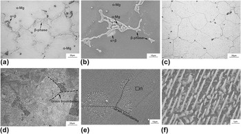
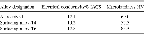
The micrograph of the AZ91 alloy under various conditions is presented in Fig. 2. As presented in Fig. 2(a), the microstructure of the as-received samples consisted of the β-intermetallic phase, Mg17Al12, precipitated in the α-Mg matrix. To obtain a better view acquisition, the SEM micrograph is presented in Fig. 2(b). It could be observed that the β-phase formed the reticulate structure with the eutectic α-Mg in the grid. A lamellar α + β eutectic mixture is attached to the precipitates. Similar observations were reported in as-cast AZ91 magnesium alloys by other researchers. Reference Chye, Zamzuri, Norbahiyah, Ismail, Derman and Illias8–Reference Luong, Shunmugasamy, Cox, Gupta and Rohatgi10 Feng et al. Reference Feng and Ma11 and Lü et al. Reference Lü, Wang, Ding, Zeng and Zhu12 reported that the interface between the coarse β-Mg17Al12 and α-Mg was easy to produce stress concentration and tended to generate cracks in the process of deformation, which had an adverse effect on the mechanical properties. Figure 2(c) presents the optical micrograph of the surfacing alloys following the T4 heat treatment. Subsequently to the solid solution, the Mg17Al12 phase dissolved into α-Mg and produced a microstructure consisted of the supersaturated α-Mg phase, which led to the poor electrical conductivity and low hardness in Table II.
Micrograph of the surfacing alloys: (a) as-received; (b) the SEM micrograph of (a); (c) surfacing alloy-T4; (d) surfacing alloy-T6; (e) the FESEM micrograph of (d); (f) the corresponding enlarged view of (e).

Electrical conductivity and microhardness of the tested surfacing alloys.

The optical micrograph of the AZ91 surfacing alloys treated by T6 is presented in Fig. 2(d). It could be observed that high amounts of precipitates existed following aging. Figure 2(e) demonstrates the FESEM micrographs of the samples. The pictures display that the β-phase was precipitated from the supersaturated α-Mg solid solution in two forms: the discontinuous precipitation and the continuous precipitation. Reference Zhou, Shen and Aung13–Reference Duly, Simon and Brechet15 The discontinuous precipitation is the cellular growth of the β-phase and α-Mg alternating layers at the grain boundaries [Fig. 2(e)]. Reference Celotto5 It could be observed that the β-phase varied in size, ranging from 0.5 to 6 μm. Also, the continuous precipitation led to the formation of dot-shaped, fine needle like β-precipitates within the grains [Fig. 2(f)], which were believed to improve the strength through the dislocation–particle interaction by the Orowan process. Consequently, the surfacing alloy of AZ91 following the T6 treatment had the highest macrohardness (Table II).
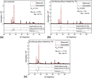
The measured and calculated X-ray diffractogram of the surfacing alloys is presented in Fig. 3. As presented in the picture, the calculated intensities (I cal.) were compared with those observed (I obs.) and the factors R wp and results of quantitative analysis were also analyzed. As can be seen, the solution heat treatment (T4) was responsible for the diffraction peak intensities disappearance of the β-phase [Fig. 3(b)]. The aluminum atoms dissolution was effective in the low electric conductivity of the T4 treated surfacing layer (Table II). The β-phase peaks were detected again following the T6 treatment [Fig. 3(c)]. The quantitative analysis results demonstrated that the volume fraction of β-Mg17Al12 in the as-received alloy was 5.9% [Fig. 3(a)], whereas in the T6 treated sample it was 11.3% [Fig. 3(c)]. In consequence, the amount of β-Mg17Al12 was significantly increased due to the T6 heat treatment.
The measured and calculated X-ray diffractogram of the surfacing alloys. (a) As-received; (b) surfacing alloy treated by T4; (c) surfacing alloy treated by T6.

B. Wear properties
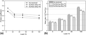
The friction coefficients for all three alloys are plotted against the applied loads in Fig. 4(a). As presented in the chart, the friction coefficients of the alloys with various heat treatment conditions exhibited a similar trend as the load increased, such as the former rapidly decreased at a low load, gradually decreased at a medium load, and finally decreased to the lowest level at a high load. The load affected the wear behavior by contact area and deformation. During sliding, the metal surface was in an elastic–plastic state. The real contact area consisted of quite low contacts at the asperity tips and was not linearly related to the load. With increasing applied load, these asperities participated in sustaining the normal pressure by generating a higher plastic deformation, leading to the decrease of the friction coefficient. Reference Ramezani and Ripin16 On the other hand, as the load increased, the thermal softening and melting of the contact surface caused by the high amount of frictional heat allowed an easier sliding at the interface. Reference Zafari, Ghasemi and Mahmudi17
(a) Friction coefficients and (b) wear rates of the tested alloys under different applied loads.

Fig. 4(b) presents the variation of the volumetric wear rates versus the applied load for the surfacing alloys. The volumetric wear rate was estimated in mm3/m by the mass loss division by the density of the alloys. It was evident that at the low applied loads of 5, 25, and 50 N, the wear rates increased linearly. Also, no drastic increase existed until the highest load was reached, whereas the wear rates of the sample at 100 N were approximately 1.5 times higher than the load of 50 N. This indicated that a transition from the mild wear to the severe wear had occurred. These results coincide with the reported results in other investigations. Reference Selvan and Ramanathan18,Reference An, Li, Lu, Chen, Xu, Chen and Wang19
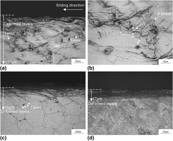
At all applied loads, the AZ91 surfacing alloy without heat treatment had a higher wear rate than the specimens subjected to T4 at constant loads, whereas the alloy subjected to T4 had the lowest hardness. It did not follow the Archard’s law Reference Archard20 and the results were obtained by Xu Zhen et al. Reference Taltavull, Torres, López and Rams21,Reference Zhen, Zhihao, Dongyue, Qingqiang and Zhanzhi22 The massive β-Mg17Al12 phase existing in the as-received surfacing alloy might have been the main reason for this difference. During sliding, the massive phase might detach from the matrix and become particles that adhere between the asperities, possibly hindering sliding and increasing the frictional force. Reference Ramezani and Ripin16 Furthermore, the interface between the crude β-phase and α-Mg was easy to produce stress concentration and generate a mass of twins, as presented in Figs. 5(a) and 5(b). As the wear continued, the cracks tended to grow and spread on the surface, which aggravated the delamination wear. This was the main factor for the poor wear resistance during the severe wear stage (a load of 100 N). The T4 treatment resulted in the dissolution of the massive β-Mg17Al12 phase, reducing the number of crack sources and leading to the wear resistance improvement. Besides, the deformed layers of the surfacing sample subjected to T4 were shallower than the as-received sample layers [Fig. 5(c)].
Micrographs of the subsurface of surfacing alloys after sliding under an applied load of 100 N. (a) As-received; (b) the corresponding enlarged view of (a); (c) surfacing alloy-T4; (d) surfacing alloy-T6.

In contrast, the wear rate of the surfacing alloy of AZ91 treated by T6 was the least in value with respect to the various alloys under constant sliding conditions. This phenomenon might be related to the β-phases precipitation during aging. The β-phases distributed at the grain boundaries could pin the boundaries and hinder sliding and migration. Moreover, the fine f-compounds in the form of continuous precipitates were strongly bonded into the matrix, which resisted the hard particles wear effect. As a result, no twins were observed in the micrographs [Fig. 5(d)] and the depth of the deformed layers of the surfacing alloy treated by T6 was the shallowest in Fig. 5.
C. Wear mechanisms
The wear properties’ change of the surfacing samples was correlated with various wear mechanisms under each wear condition. For the wear mechanisms that occurred in each wear condition test to be identified, the worn surface and debris of the worn specimens were analyzed. The results disclosed four different wear operating mechanisms: abrasion, oxidation, delamination, and plastic deformation.
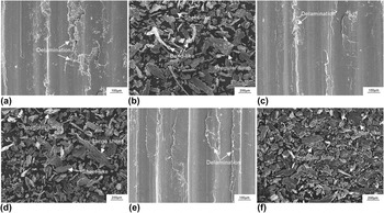
Figure 6 presents the SEM micrograph of the worn surface following sliding under the 100 N applied load. It could be observed that severe delamination occurred during the as-received AZ91 surfacing alloy wear [Fig. 6(a)]. A mass of lumps stripped from the contact surface of the sample and formed irregular and high amount of wear debris, as presented in Fig. 6(d). Furthermore, both the area and depth of the delaminated craters were significantly reduced in the surfacing metal treated by T4 [Fig. 6(e)]. As aforementioned in a previous paper, the solid solution treatment resulted in the dissolution of the massive β-phase and retarded the speed of crack initiation and growth. As it could be observed in Fig. 6(c), the worn surface of the T6 treated surfacing alloy under the 100 N applied load was quite smoother than the untreated alloy surface. This occurred because the presence of fine and dispersed β-phases precipitated in the grains, which were strongly bonded into the matrix, hindered the dislocation motion, and resisted the hard particles wear effect. As a result, the sequential surface destruction was difficult to occur. The debris morphologies of the alloys treated by T6 are presented in Fig. 6(f). The band-like and fine debris were suggested to be the result from the abrasive wear, whereas the sheets or the irregular lumps resulted from delamination. It appeared that the debris average size generated by the alloys treated by T6 was lower than the other alloys, which was indicated as a relatively moderate wear.
SEM micrograph of the worn surface and debris after sliding under an applied load of 100 N. (a, d) As-received; (b, e) surfacing alloy-T4; (c, f) surfacing alloy-T6.

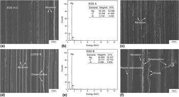
The SEM images of the worn surface of the surfacing AZ91 magnesium alloy treated by T6 under various applied loads ranging from 5 to 100 N are presented in Fig. 7. It could be observed that numerous grooves were parallel to the sliding direction on the surfaces of most pins, which are presented dominant in Figs. 7(a), 7(c), and 7(d). These scratches were the characteristics of abrasive wear, which could be attributed to the hard asperities on the steel counter-face or the detached particles that were removed from the pin and placed at surface contact. Reference Archard20,Reference Moussa, Waly and El-Sheikh23 This phenomenon is generally recognized as the common wear mechanism at low loads for the sliding wear of magnesium alloys. Reference Yan and Wang6,Reference An, Li, Lu, Chen, Xu, Chen and Wang19,Reference Jiang, Bi, Zzhao, Li, Lian and Jiang24 The increased applied load resulted in the stronger cutting and plowing on the pin, which could be responsible for the deeper and wider grooves.
SEM micrograph and the results of EDS of the worn surface of the AZ91 surfacing alloys with T6 after sliding under different applied loads: (a) 5 N; (b) EDS analysis of region A depicted in (a); (c) 25 N; (d) 50 N; (e) EDS analysis of region B depicted in (d); (f) 100 N.

As presented in Figs. 7(b) and 7(e), the energy disperse spectroscopy (EDS) analysis of regions A and B marked in Figs. 7(a) and 7(d) identified the strong O peaks, which indicated the oxide films existence on the sample pin surfaces. These results were indicative of oxidative wear. It was believed that the oxidation of the surface could be attributed to frictional heating during sliding and the easily oxidized nature of magnesium. Reference Yan and Wang6 An et al. Reference An, Li, Lu, Chen, Xu, Chen and Wang19 believed that the thick oxide layer could effectively protect the sliding surface and result in a mild wear condition. Selvan et al. Reference Selvan and Ramanathan18,Reference Stott and Wood25 reported that the sinking on the wear surface could be filled with oxide fragments, which could become compacted into a protective layer that would prevent the metal-to-metal contact resulting in a low wear rate.
With increasing load to 50 N, a series of short and shallow cracks, approximately perpendicular to the sliding direction, could be observed on the wear surface [Fig. 7(d)], indicating the appearance of the wear delamination mechanism. In this mode, the normal and shear stress were transferred through the contacting asperities to elicit a plastic strain on the surface, which promoted the nucleation and propagation of subsurface cracks in the matrix–reinforcement interfacial area. Reference Yan and Wang6 As the wear continued, the cracks tended to grow and finally lead to the surface layer detachment. As the applied load was enhanced to 100 N [Fig. 7(f)], the deep and wide delaminated craters could be evidently observed and the surface became smooth due to plastic deformation, which was generally associated to the delamination severity. Corresponding with the wear rate variation, the transition from mild to severe wear was also suggested.
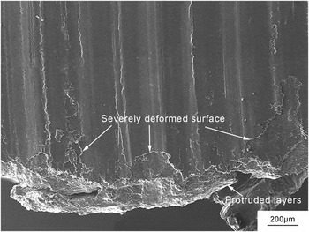
The SEM images of the protruded layers on the worn surface corresponding to the 100 N load for the surfacing sample treated by T6 are presented in Fig. 8. It could be observed that the high applied load resulted in a severe plastic deformation. The deformed surface layers were extruded along the sliding direction and consequently spread on the sample. As a result, the metallic layers were observed to be protruded slightly on the contact surface (Fig. 8) and form irregular lumps [Fig. 6(f)].
SEM images of protruded layers on the worn surface corresponding to 100 N load for the surfacing alloy with T6.

IV. CONCLUSIONS
Dry sliding wear tests of three experimental alloys were executed by a pin-on-disk configuration with applied loads ranging from 5 to 100 N at a sliding velocity of 0.78 m/s and a constant sliding distance of 1500 m at a temperature of 25 °C. The alloys included the as-received AZ91 surfacing alloys, the AZ91 surfacing alloys treated by T4 heat treatment, and the AZ91 surfacing alloys treated by the T6 heat treatment. The conclusions of this investigation were as follows:
-
(1) As the applied load increases, the alloy wear rates increased, whereas the friction coefficients decreased. The AZ91 surfacing alloys treated by the T6 heat treatment exhibited both the lowest wear rates and friction coefficients of all alloys at a certain load region.
-
(2) Four primary wear mechanisms were observed: the dominant wear mechanism was abrasion and oxidation in the load range of 5–50 N, which was related to mild wear; the delamination and plastic deformation appeared mainly at high loads (50–100 N), corresponding to the severe wear.
-
(3) The wear resistance of the alloys was affected by the modification in the corresponding microstructures and mechanical properties. Following T4 heat treatment, the dissolution of the massive β-Mg17Al12 phase reduced the stress concentration generated at the particle-to-matrix interface, leading to the wear resistance improvement. The T6 treatment could lead the β-phase to precipitate along the grain boundaries and within the α-Mg grains again. The microstructure of the T6 treated AZ91 surfacing alloys was characterized by a fine-dispersed β-phase, exhibiting a strengthening effect and resisting the wear effects. Therefore, the T6 treated AZ91 surfacing alloys displayed a better wear resistance compared to the other alloys.
ACKNOWLEDGMENTS
This work was supported by the Fundamental Research Funds for the Central Universities of China (N150904002) and the Science and Technology Program of Liaoning, China (LZ2015040).