I. INTRODUCTION
Photoelectrochemical (PEC) water splitting has become one of the most important ways to solve the global problems of energy shortage and environmental pollution through converting solar energy into chemical energy stored in hydrogen. Nowadays there are many different materials used as electrodes for PEC water splitting such as TiO2, Reference Avasare, Zhang, Avasare, Khan and Qurashi1 WO3, Reference Liu, Li, Li, Yang, Li and Chen2 ZnO Reference Hu, Yan, Gu, Chen, Bai, Kang, Long and Zhang3 , and α-Fe2O3, Reference Mishra and Chun4 etc. Among them, hematite (α-Fe2O3) has been considered to be one of the excellent PEC water splitting electrodes due to its attractive properties such as earth abundance, low cost, and excellent chemical stability. Reference Ohmori, Takahashi, Mametsuka and Suzuki5 Moreover, α-Fe2O3 exhibits suitable energy band gap of ∼2.1 eV for efficient utilization of the large portion of visible light in solar spectrum. However, there are some inevitable shortcomings for α-Fe2O3 acting as photoelectrode materials, mainly attributed to the poor electronic conductivity, high charge recombination rate, and short hole diffusion length. Reference Glasscock, Barnes, Plumb, Bendavid and Martin6 Therefore, in the past years, numerous efforts have been devoted to improve the charge transfer and separation ability of α-Fe2O3 for the enhanced PEC conversion efficiency.
As one of the most effective approaches to improve the PEC properties of α-Fe2O3 photoanodes, doping foreign elements into α-Fe2O3 has been widely adopted to promote charge transfer ability by increasing electronic conductivity. So far, a variety of metal ions, Zn, Reference Qi, She, Wang, Mu and Shi7 Ti, Reference Rioult, Belkhou, Magnan, Stanescu, Stanescu, Maccherozzi, Rountree and Barbier8 Sn, Reference Ling and Li9 etc., have been used for the doping modification of α-Fe2O3 electrodes, leading to greatly enhanced PEC performances. Kumari et al. Reference Kumari, Singh, Sonal, Deva, Shrivastav, Dass and Satsangi10 and Glasscock et al. Reference Glasscock, Barnes, Plumb and Savvides11 have shown that the Ti4+ doping can effectively improve the carrier migration rate and suppress the charge recombination, leading to a great increase in the capacity of PEC water splitting of α-Fe2O3 films. Surface modification of α-Fe2O3 by loading water oxidation cocatalysts is also effective to improve the PEC water splitting performances by accelerating surface water oxidation kinetics. For example, Zhong et al. Reference Zhong, Sun, Inumaru and Gamelin12 deposited cobalt-phosphate catalyst (Co-Pi) on the surface of α-Fe2O3 films through an electrochemical method, which accelerated the separation of electrons and holes at surface and hence promoted the water oxidation reaction, leading to the improved PEC conversion efficiency for water splitting.
Nanostructure design has been considered as another effective way to enhance PEC activity of α-Fe2O3 photoanodes by improving charge collection efficiency for surface redox reactions. Given this, different nanodesigned structures, such as NPs, Reference Li, Wang, Zhang, Chen, Cheng, Ni, Wang and Xie13 nanowires, Reference Ling, Wang, Wang, Yang and Li14 and nanorods, Reference Shen, Li, Guo, Jiang and Mao15 etc., have been developed to shorten the distance that the charge carriers have to travel to surface for water splitting reaction before recombination. Reference Shen16 Lindgren et al. Reference Lindgren, Wang, Beermann, Vayssieres, Hagfeldt and Lindquist17 prepared α-Fe2O3 nanorod arrays by low temperature solution method for the first time, exhibiting PEC conversion efficiency significantly higher than polycrystalline α-Fe2O3 NP films, which can be attributed to nanorods with small diameter shortening the carrier migration path and hence reducing charge recombination. Mao et al. Reference Mao, Han and Park18 prepared highly ordered α-Fe2O3 nanorod arrays grown on the gold nanorods, and found that the α-Fe2O3 photoelectrodes showed a high photocurrent of 8.0 mA/cm2 at 0.6 V (versus Ag/AgCl) under standard AM 1.5G illumination.
Up to now, there have been numerous methods to synthesize nanostructured α-Fe2O3 thin films, such as hydrothermal synthesis, Reference Vayssieres, Beermann, Lindquist and Hagfeldt19 atomic layer deposition, Reference Klahr, Martinson and Hamann20 pulsed laser deposition Reference Liang and Koshizaki21 , and electrochemical methods. Reference Enache, Liang and van de Krol22 Compared to these mentioned synthetic methods, electrophoretic deposition (EPD) is simple in operation and more controllable. Besides, the morphologies of α-Fe2O3 films can be easily controlled by the morphologies of the precursor α-Fe2O3 NPs and the film thickness could be then controlled by varying the EPD experimental parameters (e.g., deposition time, voltage, etc.). Zong et al. Reference Zong, Thaweesak, Xu, Xing, Zou, Lu and Wang23 found that the α-Fe2O3 films prepared by EPD showed a high photocurrent of 1.1 mA/cm2 at 1.23 V versus RHE (Reversible Hydrogen Electrode) under standard AM 1.5G illumination, whose photocurrent was higher than those α-Fe2O3 films prepared by other complex colloidal approaches. In the present study, such a simple and low cost EPD approach was used to prepare α-Fe2O3 films as photoanodes from the as-prepared α-Fe2O3 nanostructures with different morphologies. The film of α-Fe2O3 nanobars showed the highest PEC performance compared to those films of α-Fe2O3 nanorhombohedra and nanospheres, with photocurrent density reaching 0.7 mA/cm2 at 0.6 V versus Ag/AgCl. The effects of different morphologies on the PEC properties of these α-Fe2O3 films were investigated in detail.
II. EXPERIMENTAL
A. Preparation of hematite nanoparticles (α-Fe2O3 NPs) with different morphologies
α-Fe2O3 NPs with different morphologies were prepared by a hydrothermal method as follows. Reference Yanyan, Guoying, Guixiang, Yaqiu and Dongzhao24 Typically, 0.43 g of FeCl3·6H2O and 0.45 g of urea were dissolved into 43.5 mL of distilled water or glycol aqueous solution, and then sealed into a Teflon-lined autoclave, heated at 453 K for 6 h. The resulting red solid powder was collected and washed with distilled water, and acetone by centrifugation for three times, respectively. The obtained wet α-Fe2O3 NPs were redispersed into 25 mL of acetone to get a red colloid under ultrasonication for α-Fe2O3 film fabrication.
B. Fabrication of nanostructured α-Fe2O3 films
Nanostructured α-Fe2O3 films were fabricated by depositing α-Fe2O3 NPs onto conductive fluorine-doped tin dioxide (FTO) glasses via an EPD process. Typically, 5 mL of the as-prepared colloidal solution was mixed with 0.02 g of iodine followed by the addition of 45 mL of acetone under ultrasonication. Reference Zong, Thaweesak, Xu, Xing, Zou, Lu and Wang23 Two parallel FTO conductive glass substrates were immersed into the colloidal solution at a distance of 10 mm, and desired deposition time and potential using an Electrochemical Workstation were applied to deposit α-Fe2O3 NPs onto FTO substrates. Finally, the as-obtained α-Fe2O3 films were annealed in air at temperature of 973 K for 10 min, with a ramping rate of 25 K/min. For Sn4+ treated α-Fe2O3 films, the electrophoretically deposited films were immersed into a 100 mM SnCl4 aqueous solution for 2 min. The dried films were then annealed in air at 973 K for 10 min, with a ramping rate of 25 K/min.
C. Characterization
A JEOL JSM-7800F scanning electron microscope (SEM, JEOL Ltd., Tokyo, Japan) and a FEI Tecnai G2 F30 transmission electron microscope (TEM, FEI Company, Hillsboro, Oregon) were used to characterize the morphology and structure of the α-Fe2O3 NPs and nanostructured films. The x-ray diffraction (XRD) analysis of the phase and crystal structure of the films was performed by an X'pert PRO diffractometer (PANalytical, Eindhoven, The Netherlands) using Cu Kα irradiation (λ = 15.4184 nm). Reflectance and transmittance spectra of the films were performed using a double-beam UV4100 UV-Vis-NIR spectrophotometer equipment (Hitachi, Tokyo, Japan).
D. PEC measurements
PEC measurements were carried out in a three-electrode system. The α-Fe2O3 films, installed onto a self-made electrode holder with the surface areas of 0.785 cm2 as the work electrode, were illuminated from back side. The counter electrode was a platinum foil and a saturated KCl Ag/AgCl electrode was used as the reference electrode. An aqueous solution of 0.1 M NaOH and 0.1 M glucose was used as the electrolyte. Photocurrent densities were measured by a CHI 760D scanning potentiostat (CH Instruments, Shanghai, China) made in Shanghai Chen Hua Instrument Company. A 300 W Xenon lamp coupled with an AM1.5 filter was used as the light source. The light intensity was set at 100 mW/cm2. Incident photon-to-current conversion efficiency (IPCE) was measured using a Newport monochromator 74126 with a quartz convex lens. The absolute intensity of the incident light was measured by a radiometer/photometer Model IL1400BL from International Light (Chula Vista, California). IPCEλ is the IPCE corresponding to the incident light at wave length of λ and can be calculated by the equation: IPCEλ = (hc/e) (I ph,λ/λP λ), Reference Wang, Yang, Qian, Zhang and Li25 where h is the Plank's constant, c is the speed of light in vacuum, e is the elementary charge, I ph,λ represents the photocurrent density, and P λ is the power intensity of the incident monochromatic light. IPCE measurements were conducted in an aqueous solution of 0.1 M NaOH and 0.1 M glucose at 0.4 V versus Ag/AgCl. Mott–Schottky measurement in dark was conducted in an aqueous 0.1 M NaOH solution by a CHI 760D scanning potentiostat. The carrier density in these films can be calculated using the Mott–Schottky equation Reference Yang, Wolcott, Wang, Sobo, Fitzmorris, Qian, Zhang and Li26 : N d = (2/e 0εε0)[d(1/C 2)/dV]−1, where C is the capacitance between α-Fe2O3 and the electrolyte, ε is the dielectric constant of α-Fe2O3, ε0 is the permittivity of free space, e 0 is the electron charge, and N d is the donor density.
III. RESULTS AND DISCUSSION
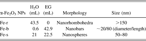
α-Fe2O3 NPs with different morphologies could be prepared by hydrothermal reaction by changing the amounts and proportion of reactive precursors during the hydrothermal experiment (see Table I and Supplementary Material).
α-Fe2O3 NPs with different morphologies synthesized in different hydrothermal conditions.

It is well known that the film thickness, which could be tuned by changing the deposition time and voltage during EPD process, will affect the PEC performance of α-Fe2O3 films as photoanodes. Increase in film thickness will give rise to improved optical absorption ability but increased charge transport distance, thus it is necessary to optimize the thickness of the α-Fe2O3 film to balance the properties of optical absorption and carrier transportation for high photocurrents. Herein, it was found that when the EPD voltage and time were set at 10 V and 30 s, respectively, the obtained α-Fe2O3 films with thickness of ca. 450 nm showed the best PEC properties (taking the Fe-r film as the example, see Figs. S1–S6 in Supplementary Material). Therefore, in the following discussion, the EPD parameters were kept at 10 V and 30 s, if there is no specific note.
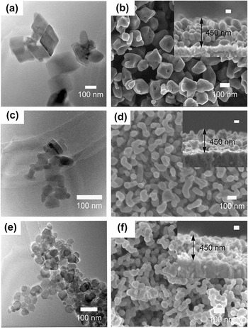
Figure 1 shows the TEM images of α-Fe2O3 NPs with different morphologies prepared by hydrothermal reaction and SEM images of nanostructured α-Fe2O3 films fabricated by EPD approach. As shown in Figs. 1(a), 1(c), and 1(e), by changing the amounts and proportions of reactive precursors in hydrothermal solution, α-Fe2O3 NPs with morphologies of nanorhombohedra (Fe-r), nanobars (Fe-b), and nanospheres (Fe-s) could be obtained. The sizes of these three α-Fe2O3 NPs were listed in Table I, as estimated from TEM images. In comparison to Fe-r with average size >150 nm, Fe-b and Fe-s showed much smaller sizes. One can easily find that Fe-b with morphology of nanobars is ca. 20 nm in diameter and 80 nm in length, while Fe-s with morphology of nanospheres is ca. 50–80 nm in diameter. After EPD at 10 V and 30 s, α-Fe2O3 nanostructured films with very similar thickness of ca. 450 nm were successfully deposited onto FTO substrates [insets in Figs. 1(b), 1(d), and 1(f)]. It was noted that in these films the α-Fe2O3 NPs kept their initial morphologies unchanged [Figs. 1(b), 1(d), and 1(f)], meaning the EPD and following annealing process did not greatly change the morphology of α-Fe2O3 NPs.
TEM images of α-Fe2O3 NPs for EPD: (a) nanorhombohedra, (c) nanobars, (e) nanospheres, and SEM images of α-Fe2O3 nanostructured films by EPD: (b) Fe-r, (d) Fe-b, (f) Fe-s.

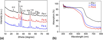
Figure 2 shows the XRD patterns and UV-Vis spectra of the α-Fe2O3 films prepared from the α-Fe2O3 NPs with various morphologies. All the films displayed the characteristic diffraction peaks of α-Fe2O3, indicating the successful deposition of α-Fe2O3 NPs onto the FTO substrates. After careful check, the obtained α-Fe2O3 NPs were found to show different diffraction peak intensities and ratios, maybe due to their different morphologies and structures, resulting in the different crystallinities. The UV-Vis spectra of α-Fe2O3 films deposited by EPD process showed an optical absorption onset at ca. 600 nm, which corresponds well with the band gap energy of ca. 2.1 eV for α-Fe2O3. It was found that the Fe-r film showed light absorption higher the other two films in the range of >600 nm, possible due to the light scattering inside the film of the rhomohedra structure. However, the photon energy of light with wavelength >600 nm is lower than the band gap energy of α-Fe2O3 and cannot generate carries in α-Fe2O3, contributing to PEC water splitting.
(a) XRD patterns and (b) UV-Vis spectra of the α-Fe2O3 films prepared from α-Fe2O3 NPs with various morphologies.

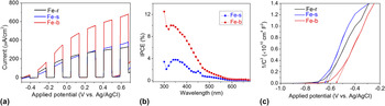
Figure 3(a) shows the current-potential curves of α-Fe2O3 films prepared from the α-Fe2O3 NPs with various morphologies. It was found that the photocurrent density of the Fe-b film was highest, reaching 0.7 mA/cm2 at 0.6 V versus Ag/AgCl. In comparison, the Fe-r and Fe-s films showed much lower PEC activities, with photocurrent density of ∼0.3 mA/cm2 at 0.6 V versus Ag/AgCl. IPCE can better characterize the PEC performance as it has no connection with the light source in the measurement. Reference Wang, Wang, Ling, Tang, Yang, Fitzmorris, Wang, Zhang and Li27 Considering the photocurrents of Fe-r and Fe-s films differed slightly, to avoid overlapped IPCE profile leading to undistinguishable comparison, herein only the IPCE values of Fe-b and Fe-s were presented. The IPCE profiles in Fig. 3(b) clearly show that the IPCE values for both the α-Fe2O3 films decreased to zero at 600 nm, which was consistent with the optical absorption profiles of the EPD fabricated α-Fe2O3 films. In comparison to the Fe-s film, the Fe-b film showed much higher IPCE values, reaching 10% at 350 nm, which again confirmed the best PEC performance for the Fe-b film. As shown in Table I and Fig. 1, the Fe-b film was composed of α-Fe2O3 nanobars with smaller diameter, which would shorten the carrier migration distance and reduce the recombination rate of photo-generated carriers in α-Fe2O3. As a result, the higher PEC activity achieved over the Fe-b film than the other two films is explainable. Mott–Schottky analysis was conducted to determine the electronic properties of these α-Fe2O3 films with different morphologies. As shown in Fig. 3(c), plots for all the α-Fe2O3 films showed positive slopes, suggesting that these samples have n-type semiconductor characteristics. With an ε value of 80 for α-Fe2O3, the carrier densities were calculated by Mott–Schottky equation Reference Yang, Wolcott, Wang, Sobo, Fitzmorris, Qian, Zhang and Li26 to be 3.7 × 1017 cm−3, 3.1 × 1017 cm−3, 3.7 × 1017 cm−3, for Fe-r, Fe-s, Fe-b, respectively. Obviously, the very similar carrier density in these films would not contribute to the great difference in PEC performances; it is then reasonable that higher PEC performance obtained for the Fe-b film should be attributed to the smaller diameter shortening the carrier migration distance and reducing the recombination rate of photo-generated carriers.
(a) Current-potential and (b) IPCE curves of the α-Fe2O3 films prepared from α-Fe2O3 NPs with various morphologies. Electrolyte: 0.1 M NaOH and 0.1 M glucose aqueous solution. Light source: 300 W Xe lamp with an AM1.5 filter. Light intensity: 100 mW/cm2, (c) Mott–Schottky measurements of the α-Fe2O3 films prepared from α-Fe2O3 NPs with various morphologies. Electrolyte: 0.1 M NaOH aqueous solution.

One will find that all these α-Fe2O3 films display relatively low PEC activity, especially in the visible light region, with IPCE values smaller than 5% [Figs. 3(a) and 3(b)]. It is generally accepted that several key factors have greatly limited the PEC activity of α-Fe2O3 as photoanodes, Reference Kennedy and Frese28 including relatively poor conductivity, high charge recombination rates, poor oxygen evolution reaction kinetics, short hole diffusion length (2–4 nm). Thus, to improve the PEC performance of α-Fe2O3 to its theoretical value, many efforts have been devoted to improve the charge transfer and separation ability of α-Fe2O3, Reference Shen16 such as element doping, co-catalysts decoration, and surface modification, etc. Among these modification approaches, surface modification is an important way to improve the PEC properties of α-Fe2O3 films, by passivating surface states for reduced surface charge recombination or speeding up the surface water oxidation reaction kinetics. Liu et al. Reference Liu, Zheng, Spurgeon and Yang29 found that the surface passivation layers could reduce charge recombination, accelerate reaction kinetics, and protect semiconductor from chemical corrosion, and thereby improve the PEC performance of semiconductors. Moreover, post-growth surface modification is always independent on the synthetic method of α-Fe2O3 films and could be potentially applied to various α-Fe2O3 nanostructures. Reference Ling and Li9,Reference Franking, Li, Lukowski, Meng, Tan, Hamers and Jin30,Reference Xi, Chiam, Mak, Tran, Barber, Loo and Wong31 For example, Xi et al. Reference Xi, Chiam, Mak, Tran, Barber, Loo and Wong31 reported that α-Fe2O3 nanorods with surface treated by Sn4+ showed great enhancement in PEC water splitting performance, with photocurrent density increased from 1.24 mA/cm2 to 2.25 mA/cm2 at 1.23 V versus RHE. Herein, to improve the PEC properties of α-Fe2O3 films, the as-deposited films were treated with Sn4+ by immersing them into SnCl4 aqueous solution (100 mM) for 2 min and then annealed in air at 973 K for 10 min.
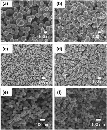
Figure 4 shows the SEM images of pristine and Sn4+-treated α-Fe2O3 films. One can find slight change to the morphologies of α-Fe2O3 films with surface becoming rougher after surface treatment with Sn4+, while the crystal structure and optical absorption property of the α-Fe2O3 films kept almost unchanged (Figs. S7 and S8 in Supplementary Material).
SEM images of α-Fe2O3 films after surface modification of Sn4+. (a, b) Fe-r, (c, d) Fe-b, (e, f) Fe-s, (a, c, e) before Sn4+ treatment, (b, d, f) after Sn4+ treatment.

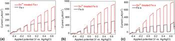
Figure 5 shows the current-potential curves of α-Fe2O3 films before and after surface modification of Sn4+. It was found the PEC property could be greatly improved after Sn4+ treatment. For the film of α-Fe2O3 nanobars, the photocurrent density was increased by 100%, reaching 1.4 mA/cm2 at 0.6 V versus Ag/AgCl. Given the almost unchanged crystal structure and optical absorption ability (as discussed in Figs. S7 and S8), the Sn4+ treatment induced PEC enhancement should be related to the reduced charge recombination, as the Sn4+ doped overlayer was supposed to passivate surface defects as well as suppress the tunneling of electrons from the α-Fe2O3 core. Reference Xi, Chiam, Mak, Tran, Barber, Loo and Wong31 Moreover, the Sn dopants can act as electron donors to increase the electron density and hence the electrical conductivity for efficient charge transfer ability. Reference Ruan, Wu, Wang, Liu, Cai, Tian, Ye, Liang and Shao32
Current-potential curves of α-Fe2O3 films after modification of Sn4+, (a) Fe-r, (b) Fe-b, (c) Fe-s. Electrolyte: 0.1 M NaOH and 0.1 M glucose aqueous solution. Light source: 300 W Xe lamp with an AM1.5 filter. Light intensity: 100 mW/cm2.

IV. CONCLUSIONS
In summary, α-Fe2O3 NPs with different morphologies (e.g., nanorhombohedra, nanobars, and nanospheres) were facilely prepared by changing the concentrations of glycol in the hydrothermal solution. The as-prepared α-Fe2O3 NPs were then used to fabricate α-Fe2O3 films by EPD for PEC hydrogen generation. It was found that the α-Fe2O3 film fabricated from α-Fe2O3 NPs in morphology of nanobars showed much higher PEC activity than those fabricated from α-Fe2O3 nanorhombohedra and nanospheres. This could be related to the small diameter of α-Fe2O3 nanobars shortening the carrier migration distance and then reducing the recombination rate of photo-generated carriers. Furthermore, it could be expected that surface treatment of Sn4+ can greatly improve the PEC performances of α-Fe2O3 films, due to the reduced surface charge recombination by passivating surface defects. This study presents a facile and scalable method for α-Fe2O3 film fabrication from the as-prepared α-Fe2O3 NPs with morphology easily controlled, paving an alternative way to optimize the morphology of photoelectrodes for improved PEC water splitting.
Supplementary Material
To view supplementary material for this article, please visit http://dx.doi.org/10.1557/jmr.2016.37.
ACKNOWLEDGMENT
The authors gratefully acknowledge the financial supports from the National Natural Science Foundation of China (Nos. 51323011 and 51236007), the Program for New Century Excellent Talents in University (No. NCET-13-0455), the Natural Science Foundation of Shaanxi Province (No. 2014KW07-02), the Natural Science Foundation of Jiangsu Province (No. BK20141212) and the Nano Research Program of Suzhou City (Nos. ZXG201442 and ZXG2013003). S. Shen was supported by the Foundation for the Author of National Excellent Doctoral Dissertation of China (No. 201335) and the “Fundamental Research Funds for the Central Universities.