I. INTRODUCTION
Rapid prototyping or additive layer manufacturing (ALM) in a layer-by-layer fashion is an emerging technology for fabricating geometrically complex components to near-net-shape that are impossible to fabricate by other processing methodologies. Reference Wong and Hernandez1,Reference Horn and Harrysson2 It also offers great potential for time and cost savings in comparison to traditional manufacturing technologies. Reference Wohlers3 In particular, aerospace and automotive components made from materials such as titanium alloys and titanium aluminides that are difficult to manufacture by conventional production processes represent interesting applications for additive manufacturing. Numerous efforts have been devoted to developing ALM processes for titanium alloys such as Ti–6Al–4V, Reference Rawal, Brantley and Karabudak4–Reference Hrabe and Quinn13 while limited work has been reported for intermetallics such as titanium aluminide. Laser melting deposition ALM was used by Qu and Wang Reference Qu and Wang14 to fabricate TiAl intermetallics and the resultant microstructure and mechanical properties were analyzed in detail. Murr et al. Reference Murr, Gaytan, Ceylan, Martinez, Martinez, Hernandez, Machado, Ramirez, Medina, Collins and Wicker15 and Biamino et al. Reference Biamino, Penna, Ackelid, Sabbadini, Tassa, Fino, Pavese, Gennaro and Badini16 have recently succeeded in producing a γ-TiAl based alloy by powder based additive manufacturing technology using electron beam melting (EBM) of prealloyed powders.
In considering the conditions necessary for additively manufactured parts, the heat source, feedstock ingredients, and the deposition process must be critically selected with the objective of achieving components with acceptable properties and shapes. Because laser or electron beam melting is predominantly used as the heat source for conventional ALM, Reference Murr, Gaytan, Ramirez, Martinez, Hernandez, Amato, Shindo, Medina and Wicker17,Reference Gu, Meiners, Wissenbach and Poprawe18 equipment capital costs are prohibitive for many commercial applications. With the continued need for reducing the cost of manufacturing processes, gas tungsten arc welding (GTAW) is an appealing option for investigating novel fabrication technology due to its high deposition rate and low equipment cost. Reference Wang, Williams and Rush19 In regards to material feedstock, most of the conventional ALM processes use prealloyed metal powders as the deposition medium. Reference Hrabe and Quinn12,Reference Hrabe and Quinn13,Reference Wang20–Reference Jia and Gu22 Depending on the powders used, the output deposits can exhibit an unacceptably high level of defects and impurities. To address this issue, the use of the material in the form of solid wire has received attention. It has been demonstrated that the wire-feeding processes are less susceptible to contamination from the atmosphere in comparison to processes using powders. Reference Brandl, Leyens and Palm23 However, the feedstock material is generally restricted to a single wire with the same composition as the substrate, although studies on wire and the arc additive manufacturing technique have been extensively documented. Reference Baufeld, der Biest and Gault24–Reference Wang, Williams, Colegrove and Antonysamy27 In addition, no information is currently available on the use of the wire based ALM process to fabricate titanium aluminides, in particular the effects of processing parameters on microstructures and properties.
In this study, an attempt has been made to fabricate titanium aluminide intermetallics via dynamic in situ alloying from separate elemental pure Ti and pure Al wires using the ALM process based on GTAW. A major concern in such a process is the effectiveness of the wire mixing behavior during production of the as-fabricated materials, which determines the microstructure and thus the uniformity of the properties. Thus the objective of this study is to better understand the microstructural characteristics of the as-fabricated titanium aluminides and their dependence on different wire feed conditions.
II. EXPERIMENTAL METHODS
The wires used in this investigation were 1.0 mm diameter commercially pure Ti wire and 0.9 mm diameter commercially pure Al wire. A 6 mm-thick pure Ti plate was used as the substrate material.
GTAW was used as the heat source to create a melt pool into which the Ti and Al wires were delivered individually by two wire-feeding units. In this case, the Ti and Al elemental wires were separately delivered into the weld pool, and the elements are mixed in the molten pool. The elemental feed rates were controlled individually by independently setting the speed of the two-wire feeding units. The first layer was bonded to the substrate. After completing a layer, the GTAW torch and the twin wire feedstock nozzles were raised vertically by a distance equal to the layer thickness. A new layer was subsequently deposited onto the previous layer until the component was fully constructed in the layer-by-layer fashion. The substrate was removed after the final product was fabricated. Four groups of Al and Ti wire feed settings were selected in this work: They were 615 mm/min Al and 765 mm/min Ti for group 1, 730 mm/min Al and 765 mm/min Ti for group 2, 855 mm/min Al and 765 mm/min Ti for group 3, and 1015 mm/min Al and 780 mm/min Ti for group 4. Their corresponding ratios of Al to Ti wire-feeding rates are 0.80, 0.95, 1.12, and 1.30, respectively for the four groups. A welding current of 120 A and 3.5 mm arc length were applied at a travel speed of 100 mm/min, and these parameters were found to be acceptable through several preliminary trials. The entire additive manufacturing process was protected from oxidation by using an appropriately designed argon gas shielding device, to produce deposits with minimal oxygen and nitrogen contamination.
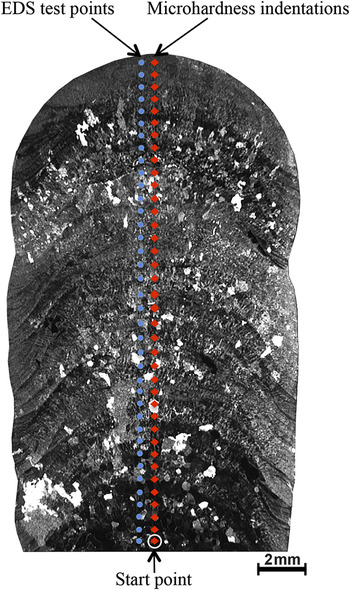
Four straight walls, all 100 mm in length, were produced. Metallographic specimens were prepared using standard metallographic procedures for titanium aluminides and examined by optical micrography and scanning electron microscopy (SEM, JEOL JSM-6490LA, Tokyo, Japan). The element distributions in the different regions of the specimens were determined by an energy dispersive x-ray spectroscopy (EDS) analysis system. The accuracy of EDS measurements is ±0.5 at.%. A GBC MMA x-ray diffractometer (XRD, GBC, Melbourne, VIC, Australia) with Cu Kα radiation (λ = 1.5418 Å) was used to identify the phase constitutions. Vickers microhardness profiles of the as-fabricated components were measured at a load of 200 g (HV0.2) by using a Duramin 70 Hardness Tester. The indentations were performed at the weld pool center line, at 1 mm intervals from the fusion line to the top of the last layer, as shown in Fig. 1. The mean hardness value and its standard deviation were then calculated for each of the four samples.
Typical cross-section morphology of the wall components produced by GTAW ALM and locations of microhardness and EDS measurements.

III. RESULTS
A. Microstructure
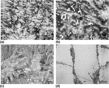
Microscopic characteristics analysis in the cross-sections of the GTAW ALM built walls does not show any appreciable change in the microstructure as a function of wire-feeding rate ratios, even though these result in significantly different Al:Ti atomic ratios. The typical microstructure within the as-fabricated walls is mainly dendrites and lamellar colonies. Various proportions of dendritic, interdendritic, and columnar structures are observed at different locations in the samples as shown in Fig. 2. The near-substrate zone presents comparatively large α2 grains as shown in Fig. 2(d). Some finer γ laths displaying more contrast variation precipitate at grain boundaries. Fully lamellar colonies with different sizes [Fig. 2(c)] and interdendritic γ structures [Fig. 2(b)] can be found as moving up samples. The finer dendrites and interdendritic γ phases surrounded by a lamellar microstructure are visible in the top layers in Fig. 2(a).
Representative microstructure in the wall components produced by GTAW ALM: (a) Top region, the white areas show the interdendritic γ phase; (b) Middle region, the white areas show the interdendritic γ phase; (c) Middle region, lamellar colonies consist of α2 and γ lamellae; (d) Bottom region, coarse α2 grains with fine γ laths precipitating at grain boundaries.

B. Chemistry composition and phase analysis
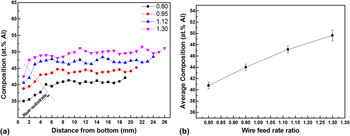
To gain a clear indication of the wire mixing behavior in the GTAW ALM fabricated wall components, compositional analysis of the as-fabricated walls was conducted by EDS measurements beside hardness indentations at approximately 0.5 mm distance (Fig. 1). The compositional measurement results are shown in Fig. 3(a). Only a small variation of Al distribution throughout the build height can be found, and that the magnitude of the variation is similar for the four different wire feed conditions. The greatest deviation from the average composition occurs near the substrate. This is expected because of dilution from the pure Ti substrate that is mixed into the weld pool during deposition of the first layer, where penetration of the weld pool into the substrate is over 2 mm. This effect is reduced as the next few layers are added, since the weld pool penetrates layers that have progressively lower Ti content. In the main part of the wall, the measurements indicate stable and uniform wire mixing.
Microchemical analysis obtained by EDS from the cross-sections of wall components produced by GTAW ALM under different wire feed conditions: (a) Quantitative Al concentration alongside the center line of the as-fabricated wall specimen; and (b) average Al intensity of the main part except the near-substrate zone.

Figure 3(b) shows the average value of the Al content for the main part of each wall, and the range of variation of the relative measurement points in Fig. 3(a). The sample with the Al:Ti feed rate ratio of 1.30 has less homogeneous Al distribution, but the variation is only marginally less than that of the other ratios. Furthermore, it can be seen clearly from Fig. 3(b) that the average Al concentration can be considerably increased by increasing the ratio from 0.80 to 1.30.
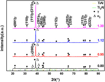
Correspondingly, the phases in the GTAW ALM fabricated walls using different wire feed conditions were identified by XRD analyses, with the results being shown in Fig. 4. All the diffraction patterns indicate that the main constituent phases are γ-TiAl and α2-Ti3Al. The predominant γ phase peak is in the (111) plane located at 2θ ≈ 39° for the walls built with an Al:Ti wire feed rate ratio of 0.80–1.12. In addition, increasing the ratio from 0.80 to 1.30 leads to more γ phase and less α2 phase. However, a bit more α2 phase can be obtained when the wire feed rate ratio is further increased to 1.30.
Phase constitutions in the wall components produced by GTAW ALM under different wire feed conditions.

C. Microhardness
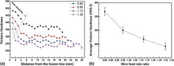
Figure 5(a) illustrates the microhardness profiles measured along the center line of the GTAW ALM-fabricated walls. It can be seen that high microhardness values are recorded in the near-substrate zone for each wall specimen. As the build-up continues, the microhardness is found to vary only slightly depending on the location. This is indicative of the consistent material feed ratio and intermixing of elements during the build process. The exception to this occurs at the near-substrate zone, for the same reasons as described earlier.
Microhardness values of wall components produced by GTAW ALM under different wire feed conditions. (a) Microhardness profiles as a function of location on the cross-sections. (b) Mean microhardness values of the main part except the near-substrate zone. Error bars show one standard deviation.

In addition, the mean microhardness value and the standard deviation of the main part of the wall (except the near-substrate zone) for each GTAW ALM-fabricated wall are shown in Fig. 5(b). The results indicate that reducing the Al:Ti wire feed rate ratio from 1.30 to 0.80 can produce significantly harder materials.
IV. DISCUSSION
A. Microstructure and composition
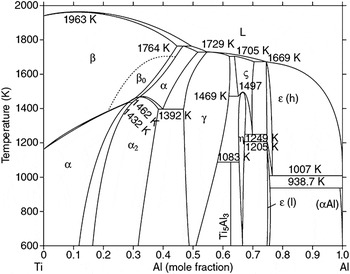
Engineering alloys based on the γ(TiAl) phase usually have 44–48 at.% Al. According to the binary Ti–Al phase diagram (Fig. 6), Reference Witusiewicz, Bondar, Hecht, Rex and Velikanova28 these structural materials contain the γ(TiAl) phase with the tetragonal L10 structure and minor fractions of the α2(Ti3Al) phase with the hexagonal D019 structure. The microstructure features can be attributed to the complex thermal history Reference Choi, Deng, McCullough, Paden and Mehrabian29 that is implicit in the GTAW ALM build process, rather than the processing parameters such as wire-feeding rate. Solidification microstructures during the initial welding passes generally exhibit epitaxial growth from the adjacent melted substrate. The preferential direction of grain growth is almost perpendicular to the solid/liquid interface, as the maximum driving force for solidification comes from the direction of the maximum temperature gradient. Meanwhile, a high cooling rate is expected due to chilling by conduction into the cold substrate. Therefore, the formation of α2 grains in the near-substrate zone is not only the result of more Ti contents but also the consequence of the ordering transformation α → α2, while the high temperature transformation (α → α + γ) is suppressed by a high cooling rate. Reference Arenas and Acoff30 Owing to the multiple heating and cooling cycles during the deposition of subsequent layers, the near-substrate zone is held at a higher temperature for a longer time. In this case, the α2 grains are coarsened and mostly equiaxed. As the build-up continues, the top region of the previous layer is partially remelted every time a new layer is deposited on top of the existing layer. Limited constitutional undercooling is expected to inhibit the formation of the properitectic solid phase. The resulting enrichment of Al is primarily distributed at the interdendritic regions, which then solidifies as the interdendritic γ phase at lower temperatures. Reference Oehring, Küstner, Appel and Lorenz31 In addition, solid state phase transformations inevitably occur in the heat affected zone around the melt pool and ultimately lead to the formation of the fully lamellar microstructures together with interdendritic γ phases. Reference Qu and Wang14 Since the near-surface zone of the as-fabricated wall is hardly affected by the heat, much more and finer interdendritic γ grains are observable.
The binary phase diagram of the Ti–Al system.

The EDS measurements and XRD phase analyses on each wall specimen support the above statements. The results also indicate that various wire feed conditions can significantly influence the proportion of Al in the as-fabricated materials and subsequently give appreciable variation of the proportion for the two different phases. This phenomenon can be expected based on the phase diagram (Fig. 6) Reference Witusiewicz, Bondar, Hecht, Rex and Velikanova28 as discussed above. However, it is interesting that increasing the ratio to 1.30 fails to further reduce the proportion of the α2 phase. It should be noted that the variations in the feeding rates of a filler metal applied to a weld might result in different arc lengths and, hence, different arc voltages. That variation directly affects the heat input. The higher the total wire feed rate, the more the welding arc energy is needed to melt the filler metal, so less energy is available for melting of the weld pool and heating of the surrounding material. This effect should result in a relatively lower cooling rate. In this case, both the ordering transformation α → α2 and the high temperature transformation (α → α + γ) occur together. As a consequence, slightly more α2 phase can be expected with a significant increase in the total wire feed rate.
B. Microhardness
As discussed above, the microhardness values of GTAW ALM-fabricated wall components are strongly dependent on the Al content, which is determined by the wire feed rate ratio. As the Al content increases, the volume fraction of the γ phase increases accompanied by a decrease in the α2 phase. Goken et al. Reference Göken, Kempf and Nix32 found a significant difference in hardness between the α2 and γ phases in the case of polysynthetically twinned crystals. The hardness of the γ phase is almost half of the α2 phase. Therefore, the increased microhardness values of the low Al content result from the increased α2 phase content. With respect to the microhardness variation as a function of location in each wall, the cooling rate is the key factor that controls the proportion of the α2 phase and further influences the microhardness values.
V. CONCLUSIONS
In situ alloying and ALM based on the GTAW process with separate wire feed of the alloying elements offers a novel technology to produce γ-TiAl based alloy wall components. The effect of the ratio between the Al and Ti wire-feeding rate has been investigated. With increasing the wire feed rate ratio from 0.80 to 1.30, the Al composition and the γ phase increase, and the microhardness decreases as expected. However, an unexpected increase in the α2 phase has been found when the wire feed rate ratio is increased further to 1.30. The slightly lower cooling rate due to the higher total wire-feeding rate should be the cause of this effect.
Additionally, the results also show that the chemical composition is generally uniform through the as-fabricated walls, apart from the near-substrate zone. Therefore, uniform weld and material properties throughout the height of each wall can be expected. A key factor in this manufacturing technique is to precisely control the Al and Ti wire feeding rates to obtain the desired composition in the final materials.
ACKNOWLEDGMENT
The authors acknowledge financial support from the China Scholarship Council (CSC), the University of Wollongong, and the Welding Technology Institute of Australia (WTIA), and use of the facilities within the UOW Electron Microscopy Centre.