Introduction
With the rapid advancement of communication technologies, wireless systems have become a crucial component in modern communication networks. Multiband patch antennas, in particular, have attracted significant interest due to their capability to handle multiple frequency bands. While patch antennas are favored for their low-profile, lightweight nature, cost-effectiveness, and ease of integration compared to conventional antennas, they still suffer from various drawbacks, such as limited impedance bandwidth and moderate gain.
Gain is one of the most important antenna parameters, and the need to improve it has become a priority for many researchers in recent years. Metamaterial resonating structures [Reference Nguyen1–Reference Wang, Liu, Chen, Li and Shi3], reflectors such as frequency selective surfaces [Reference Tahir, Arshad, Ullah and Flint4, Reference Kushwaha and Kumar5] and electromagnetic bandgap structures [Reference Rao and Vishwakarma6],superstrates [Reference Kim, Ahn and Bang7–Reference Khouser, Choukiker and Bhowmick9], shorting pins [Reference Liu, Tang, Wang, Li and Yin10], substrate removal [Reference Yeap and Chen11], and parasitic elements [Reference Zhang, Hoorfar and Thajudeen12] are some of the methods used to enhance the antenna gain. However, these approaches face challenges such as manufacturing complexity and structures size. A highly effective strategy for increasing antenna gain is the employment of artificial magnetic conductor (AMC) surfaces [Reference Zhong, Yang and Zhong13–Reference Yang, Yu, Yang and Zhao30].
AMCs, as metamaterials, exhibit distinctive characteristics artificially created and not naturally occurring. They can emulate perfect magnetic conductor surfaces by generating zero-degree reflection phases at their resonant frequency, and similarly mimic high impedance surface at that specific resonant frequency [Reference Zhang, Wang, Shao, Yu and Mittra31, Reference Abu, Abd Rahim, Ayop and Zubir32].
Furthermore, the application of AMCs for enhancing antenna gain has drawn the interest of numerous researchers in the literature. In paper [Reference Zhong, Yang and Zhong13], the authors succeeded in improving the gain of a wideband bow-tie antenna by around 4–6.5 dBi by integrating an AMC surface. Similarly, in paper [Reference Hazarika, Basu and Nandi14], a peak gain of 9.7 dBi was observed after employing an AMC surface. Meanwhile, in papers [Reference Sen, Banerjee, Kumar and Das15] and [Reference Joshi and Singhal17], the authors achieved a gain improvement of 5.5 and 3.74 dBi respectively over an ultra-wide impedance bandwidth by using AMC reflectors. In paper [Reference Ameen, Ramireddy and Chaudhary16], an AMC surface added to a dual-band antenna, specifically tailored for 4G-LTE, wireless local area network (WLAN), and WiMAX applications, improved the gain by 3.3 and 2.26 dBi in the respective bands. In wearable and textile antennas, it has also been demonstrated that the use of an AMC reflector increases the gain, as indicated by the authors in papers [Reference El Atrash, Abdalla and Elhennawy18] and [Reference Saha, Mitra and Parui21]. However, today there is a strong interest in boosting the gain in more than one or two frequency bands. For example, in paper [Reference Gong, Yang, Li, Chen, Tong and Yu20], the researcher applied a quad-band AMC consisting of four metallic nested rings, with the innermost ring linked in series to four lumped capacitors to increase the gain of a quad-band antenna designed for WLAN, WiMAX, and 5G mobile communication systems. This led to an increase in gain of 4.93 dBi, 5.92 dBi, 5.54 dBi, and 4.95 dBi across the four operational frequencies. Additionally, in [Reference Yang, Yu, Yang and Zhao30], the authors boosted the gain of a tri band antenna for WBAN applications using a three-zero phase AMC reflector, with an increase of 3.4, 1. 8, and 4 dBi in the respective three operating frequencies.
All the aforementioned studies demonstrate that the implementation of AMCs contributes to gain improvement but at the cost of large and complex structures.
In this work, a novel antenna design that integrates an elliptical split-ring resonator (SRR) antenna with a customized AMC array to achieve a compact, high-gain, and multiband performance is proposed. This work combines these two elements innovatively to enhance the gain and achieve a tri-band operation across 2.33–2.59, 4.97–5.48, and 7.48–8.59 GHz. The proposed design demonstrates significant improvements in gain, compactness, and compatibility for wireless applications and satellite communications. Specifically, the antenna achieves gain enhancements of 3.4, 5.65, and 1.5 dBi across the three frequency bands, thanks to the integration of an AMC reflector with three zero-phase of the reflection coefficient.
The remainder of this manuscript is organized as follows. The “Antenna design” section details the design methodology and simulation results of the proposed antenna. The “AMC unit cell design” section introduces the AMC structure unit cell while the “AMC–antenna combination” section presents the integration of the antenna with the AMC array, including simulation results and parametric studies of the combined structure. The “Results and discussion” section discusses the fabrication process and experimental validation along with a performance comparison with existing designs. Finally, the “Conclusion” section concludes the study with a summary of findings.
Research Articles – These papers describe new results in the field of microwave and wireless technologies.
Antenna design
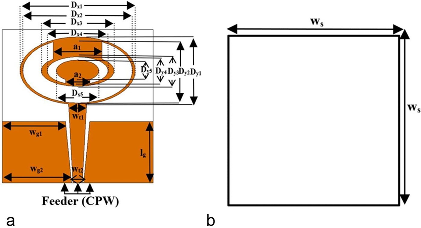
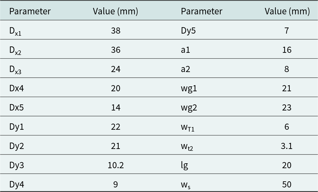
The antenna outlined in this paper consists of a radiating patch printed on an FR4 substrate with a permittivity of 4.4, a loss tangent of 0.025, and a thickness of 1.6 mm . A coplanar waveguide (CPW), depicted in Fig. 1, is employed to feed the antenna. The radiating element features an elliptical shape, while the SRR technique is incorporated to achieve a tri-band behavior. The antenna operates at the frequencies of 2.27, 5.2, and 8 GHz. Table 1 summarized the optimized geometric parameters of the proposed antenna, while the physical dimensions are 50 mm × 50 mm × 1.6 mm (0.41λ0 × 0.41λ0 × 0.01λ0, where λ0 represents the free-space wavelength at the lowest operational frequency).
The proposed structure: (a) overall view and (b) back view.

The antenna dimensions

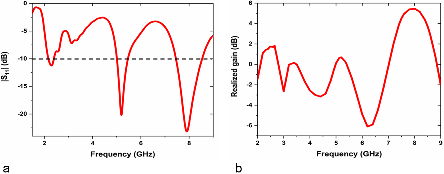
The simulated results in terms of reflection coefficient and gain are given in Fig. 2.
Simulated results: (a) reflection coefficient and (b) realized gain.

The simulated reflection coefficient results, as shown in Fig. 2(a), indicate that the proposed structure exhibits tri-band behavior, with frequency ranges of 2.16–2.39, 5.01–5.46, and 7.45–8.54 GHz. Figure 2(b) demonstrates that the gain is notably low in the first two bands, particularly in the second band.
AMC unit cell design
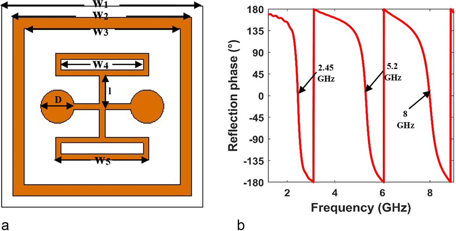
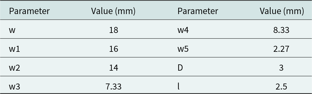
Figure 3 illustrates the finalized design of the proposed AMC unit cell and its corresponding reflection phase. The AMC unit cell is based on FR4 material. The top face of the FR4 substrate is covered with metallic patches, while the bottom face is entirely coated with metal. All the geometric parameters of the proposed unit cell are presented in Table 2.
(a) The proposed AMC unit cell and (b) the corresponding reflection phase.

The unit cell’s dimensions

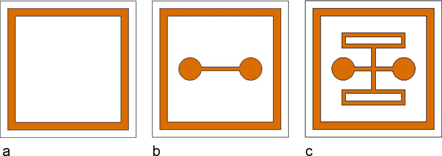
To achieve the optimized structure, several steps were considered, as demonstrated in Fig. 4. Meanwhile, Fig. 5 depicts the results pertaining to each structure.
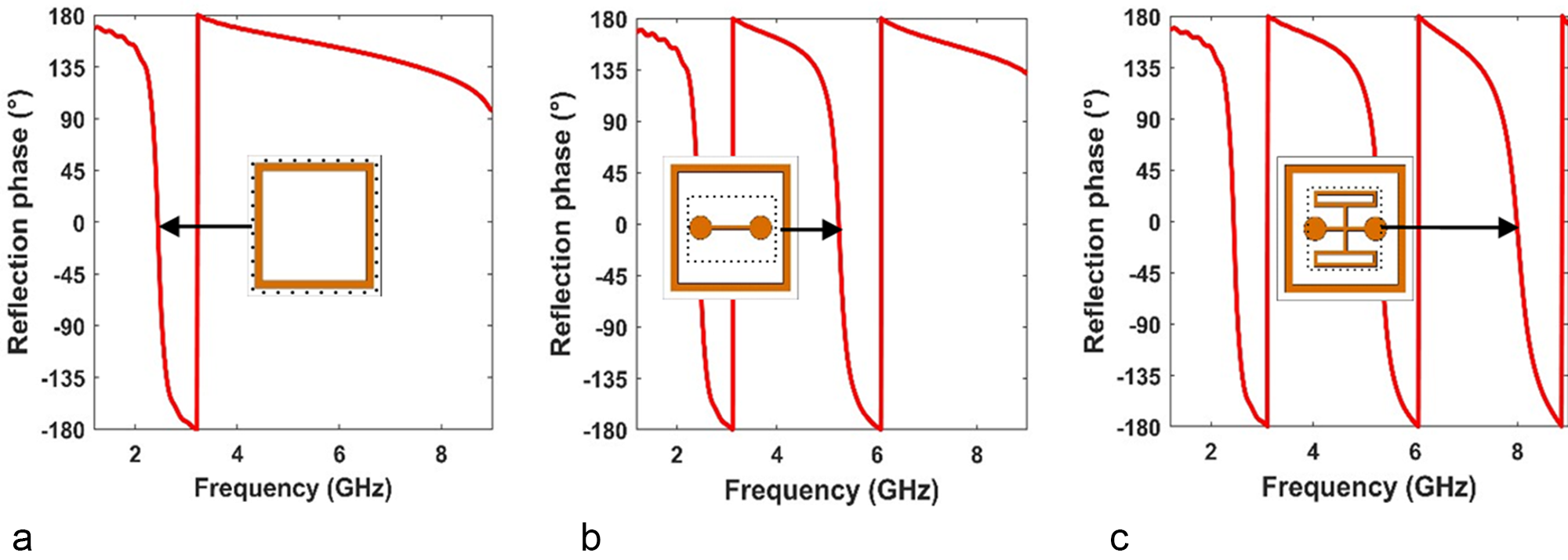
As a first step, a simple rectangular patch is designed, as illustrated in Fig. 4(a). It is noted that the cell exhibited zero reflection phase at 2.45 GHz Fig. 5(a). Subsequently, to achieve tri-band behavior, some geometries were added incrementally, as depicted respectively in Fig. 4(b) and (c). Each geometry corresponds to a zero-reflection phase, as shown in Fig. 5(b) and (c).
(a) First step, (b) second step, and (c) third step.

Reflection phase for the different steps. (a) First reflection phase, (b) Second reflection phase and (c) Third reflection phase.

AMC–antenna combination
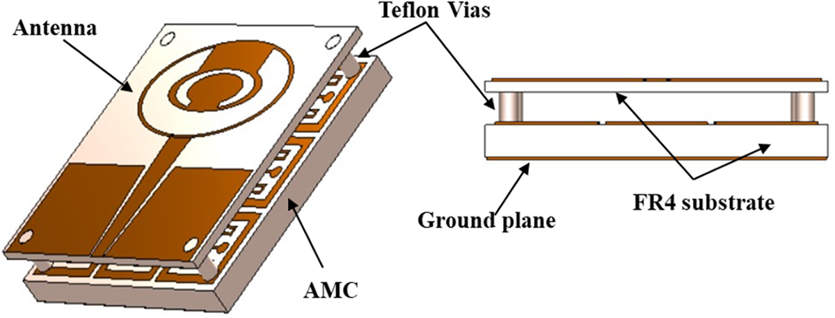
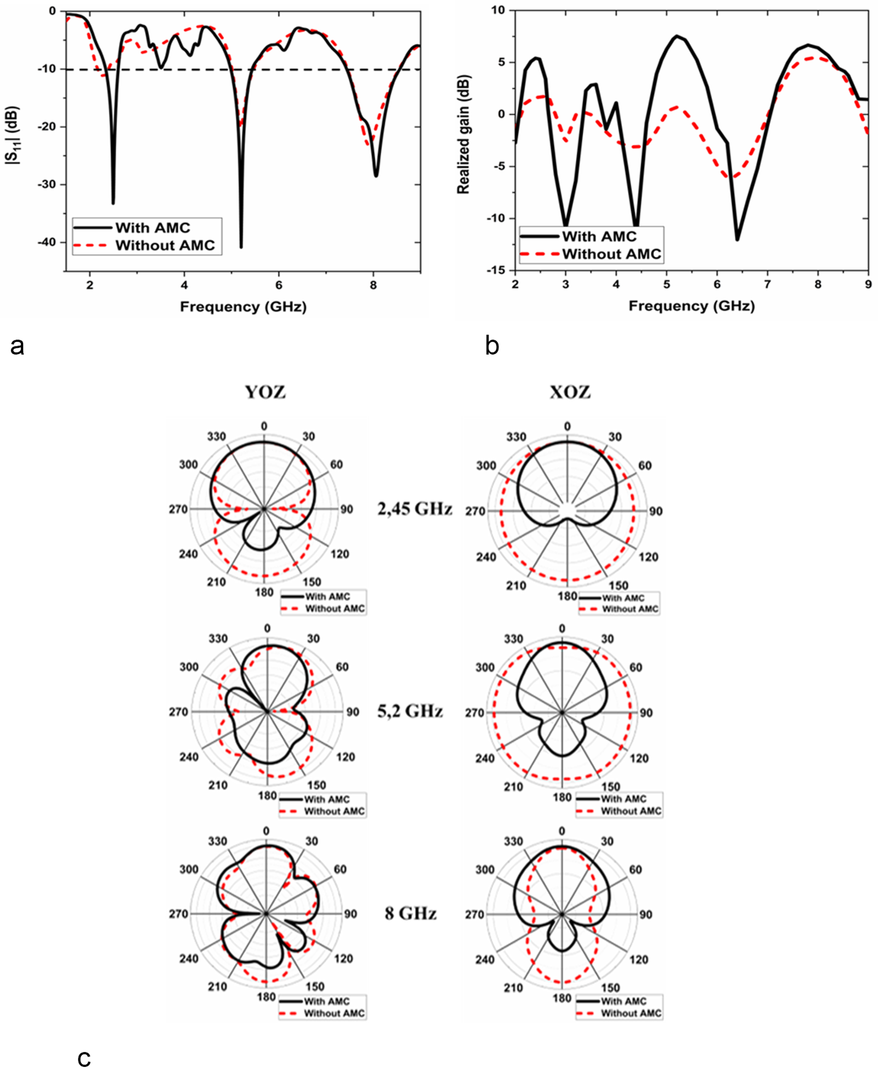
To improve the low gain observed in the first two bands, particularly in the second one Fig. 2(b), an AMC structure was added beneath the antenna Fig. 6. Figure 7 presents the simulation results of the proposed AMC-backed antenna structure in comparison to those of the standalone antenna. The width ws of the antenna Fig. 1(b) was increased from 50 to 52 mm due to the addition of Teflon vias.
Despite the integration of an AMC structure, the simulated results indicate that the AMC-backed antenna still operates at three distinct frequency bands where |S11| ≤ −10 dB, which are 2.33–2.59, 4.97–5.48, and 7.48-8.59 GHz, as depicted in Fig. 7(a). Additionally, the inclusion of the AMC structure improves the performance of the first frequency band. Figure 7(b) demonstrates the impact of the AMC array on gain enhancement, revealing improvements of 3.92, 6.57, and 1.79 dBi at 2.45, 5.2, and 8 GHz, respectively, with peak gains reaching 5.40, 7.53, and 6.39 dBi at these frequencies. These results indicate that the AMC structure not only enhances the gain but also significantly improves the overall performance of the antenna.
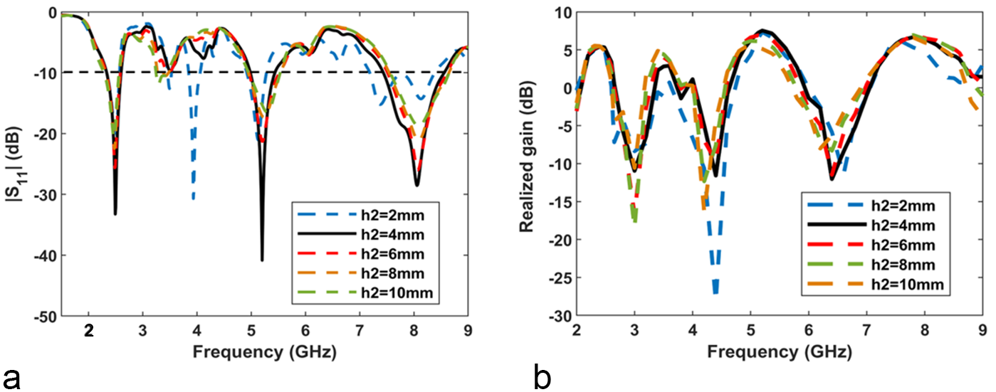
One can note that in all operational frequency bands (2.45, 5.2, and 8 GHz), the presence of the AMC significantly enhances the directivity of the antenna. Several parametric studies were needed to achieve the desired results. Starting with the optimization of the air gap h2 (the distance between the antenna and the AMC, Fig. 6). The results, shown in Fig. 8, indicate that the optimal simulated performance was achieved when h2 = 4 mm.
The proposed antenna-backed AMC.

Simulated results with/without AMC: (a) reflection coefficient, (b) realized gain, and (c) radiation patterns.

Parametric study of the air gap influence for different values of h2: (a) reflection coefficient and (b) realized gain.

Figure 8(a) displays the |S11| of the proposed AMC-backed antenna for different h2 values. The results highlight the sensitivity of the prototype’s impedance bandwidths to h2. Performance is notably inadequate at h2 = 2 mm, but improves significantly within the range of 4–10 mm, displaying a multiband behavior. Additionally, Fig. 8(b) shows that the optimal realized gain is achieved with h2 set at 4 mm. To maintain a low-profile structure while maximizing the gain, h2 = 4 mm is selected for the air gap.
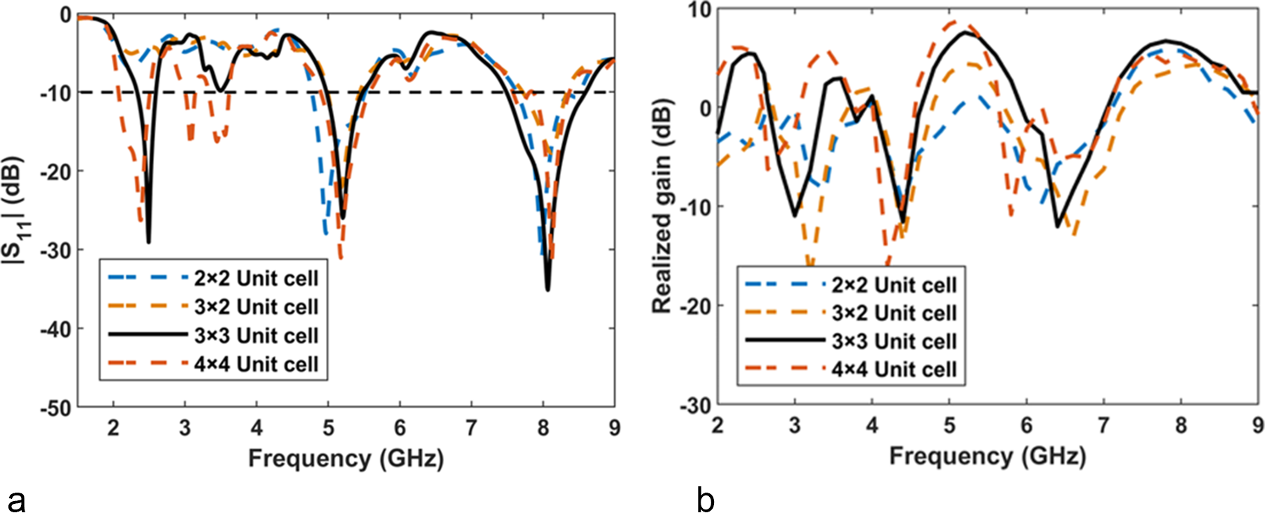
The second study is focused on the AMC array size. This study evaluated the effects of various array sizes on the reflection coefficient and realized gain. Figure 9 highlights that the 3 × 3 AMC array size yielded the best performance.
Parametric study of the AMC array size: (a) reflection coefficient and (b) realized gain.

Figure 9(a) demonstrates that the first band fails to achieve the required impedance matching in the first two configurations (AMC with 2 × 2 and 3 × 2 unit cells), with optimal matching observed using the 3 × 3 AMC unit cell. Furthermore, Fig. 9(b) shows that as the number of AMC unit cells increases, the gains at the first and the second resonant frequencies also increase. However, switching the array from 3 × 3 to 4 × 4 decreases the gain of the AMC-backed antenna by 1.22 dBi at 8 GHz, although it shows a slight improvement at 2.45 and 5.2 GHz. Considering the reflection coefficients, gains, and dimensions, the 3 × 3 configuration appears to be the optimal design. So, this is the solution chosen for the fabrication.
All the simulated results presented in this paper were generated using CST Studio Suite software.
Results and discussion
To verify the simulation results, the proposed prototype was fabricated and tested. The fabricated structure is depicted in Fig. 10, while the simulated and measured reflection coefficients of the prototypes, both with and without the AMC, are shown in Fig. 11. The radiation patterns (E-plane and H-plane) and gain were measured in the IEMN anechoic chamber using a standard horn antenna (SAS–200/571) and an Agilent PNA-X series N5242A Vector Network Analyzer (operating from 10 MHz to 26.5 GHz). The SAS–200/571 horn antenna operates over a frequency range of 700 MHz to 18 GHz, with a gain varying from 1.4 to 15 dBi. Its −3 dB beamwidth averages 48° in the E-plane and 30° in the H-plane. The radiation patterns were measured with 360 points per turn, using an intermediate frequency (IF) bandwidth of 10 kHz, a transmission power of 0 dBm, and a sweep time of approximately 34 seconds per full rotation. For reflection coefficient measurements, the Agilent PNA-X N5242A Vector Network Analyzer was used in a frequency range of 1–11 GHz with a frequency sweep (linear) of 401 points and an IF bandwidth of 10 kHz.
Fabricated structure: (a) top view, (b) bottom view, (c) AMC reflector, (d) and (e) measurement setups.

Comparison of simulated and measured results: Reflection coefficient of the antenna (a) without AMC and (b) with AMC.

The measured |S11| of the antenna without the AMC as shown Fig. 11(a) exhibits a tri-band behavior that closely aligns with the simulated results, and in some cases, shows very good agreement. However, slight discrepancies are observed in the first operational band, where the simulation indicates weak impedance matching, whereas the measured results demonstrate good impedance matching. On the other hand, as depicted in Fig. 11(b), the simulated and measured |S11| of the whole structure (antenna + AMC) are very close, demonstrating the efficiency of the AMC structure. Overall, the simulated and measured results of the proposed tri-band antenna are in good agreement for both cases – with and without AMC. The minor deviations are mainly attributed to manufacturing.
Figure 12 depicts the normalized 2D radiation patterns of the proposed structure (antenna-backed AMC) in both E-plane and H-plane at the three resonant frequencies.
Comparison of simulated and measured results of the radiation patterns at the three operational frequencies (a) without AMC and (b) with AMC.

As shown in Fig. 12(a), the radiation pattern of the single antenna exhibits an omnidirectional pattern for both the simulated and measured results, with minor discrepancies in the measured results attributed to manufacturing errors. In contrast, the antenna with the AMC reflector displays a more directional pattern due to the AMC’s effect (Fig. 12(b)).The measured results for this configuration are in close agreement with the simulated results.
The proposed structure’s gains at frequencies around 2.45, 5.2, and 8 GHz have been simulated and measured, as illustrated in Fig. 13.
Comparison of simulated and measured results of the realized structure: (a) without AMC and (b) with AMC.

The measured results show that the gain increases by 3.4 dBi at 2.45 GHz, 5.65 dBi at 5.2 GHz, and 1.5 dBi at 8 GHz with the incorporation of the AMC structure, compared to an improvement of 3.89, 6.7, and 0.95 dBi in the simulations at the same resonant frequencies (Fig. 13(a) and (b)). The peak measured gains of the antenna-backed AMC at 2.45, 5.2, and 8 GHz are 4.7, 6.05, and 7.2 dBi, respectively, while the simulated ones are 5.7, 7.53, and 6.39 dBi. Both the simulated and measured results confirm that the AMC reflector effectively boosts the antenna’s performance, with a notable increase in gain at each frequency. These results shed light on the performance improvements provided by the AMC reflector and highlight the agreement between simulated and measured results.
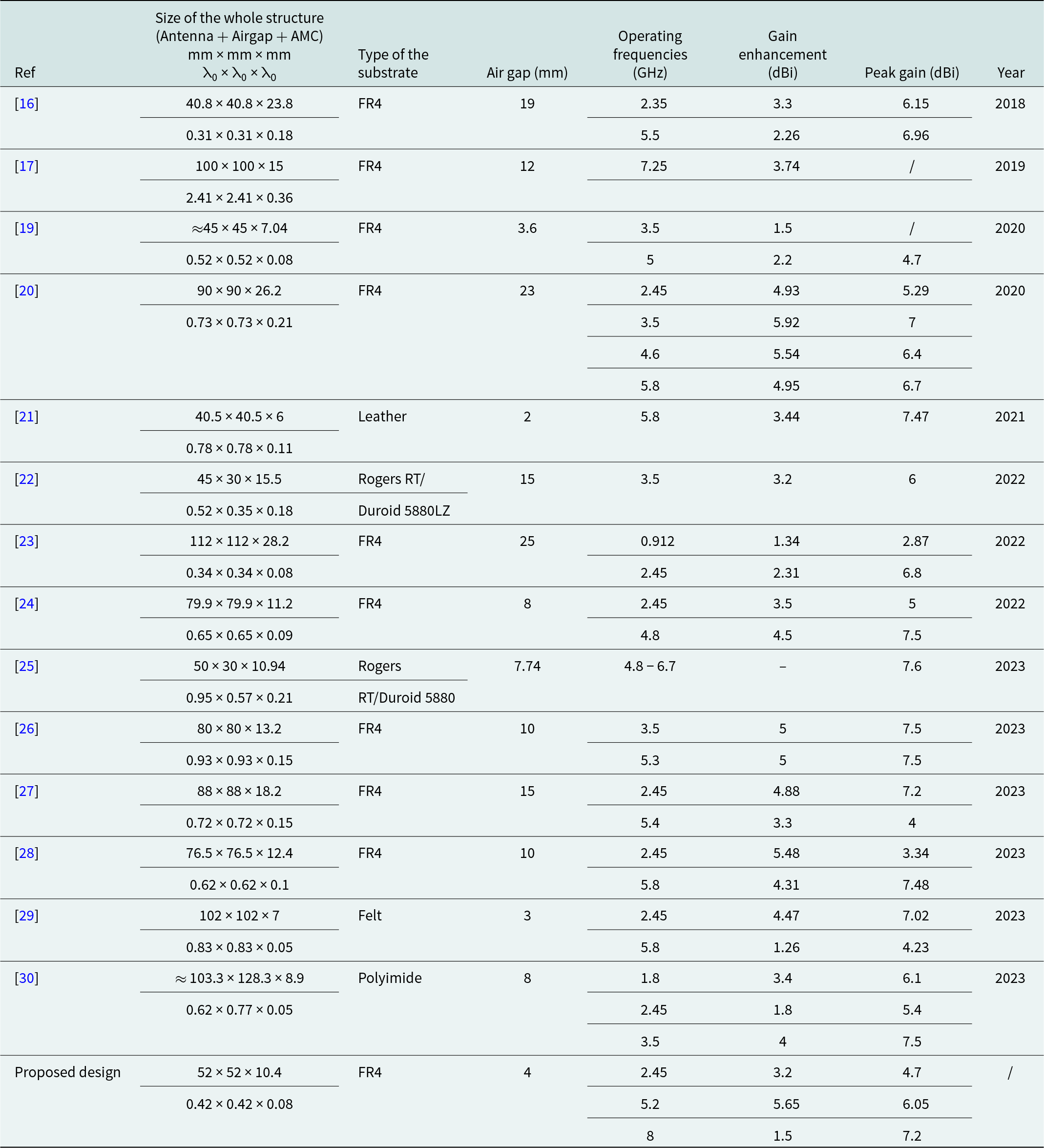
Table 3 presents a performance comparison with earlier publications, highlighting the notable features of the proposed design, such as reduced size and enhanced gain. The proposed design demonstrates several advantages compared to the existing literature. Most of the referenced designs are significantly larger than the proposed design when normalized to the operating wavelength (λ0). For instance, designs such as in papers [Reference Joshi and Singhal17] and [Reference Gong, Yang, Li, Chen, Tong and Yu20] are considerably bulkier, making them less suitable for applications requiring compactness. While smaller designs, such as the ones in papers [Reference Ameen, Ramireddy and Chaudhary16] and [Reference Najumunnisa, Sastry, Madhav, Das, Hussain, Ali and Aslam23], exist, they have notable limitations. Reference [Reference Ameen, Ramireddy and Chaudhary16], for example, operates in a dual frequency band but requires a large air gap of 19 mm, which increases its overall volume and complexity. Similarly, the design proposed in paper [Reference Najumunnisa, Sastry, Madhav, Das, Hussain, Ali and Aslam23] achieves lower gain enhancement and relies on a substantial air gap of 25 mm.
Comparison of the proposed design with other reported designs from literature

Note: λ0 represents the free-space wavelength corresponding to the lowest operational frequency.
The proposed design also stands out in terms of material choice. It uses FR4, a cost-effective and widely available substrate. In contrast, many other designs use more expensive or specialized materials, such as leather [Reference Saha, Mitra and Parui21], Rogers RT/Duroid 5880Lz [Reference Abdulbari, Abdul Rahim, Abedi, Soh, Hashim, Qays and Zeain22], Rogers RT/Duroid 5880 [Reference Verma, Arya, Bhattacharya and Raghava25], felt [Reference Ali, Basir, Zada, Ullah, Kamal and Yoo29], and polyimide [Reference Yang, Yu, Yang and Zhao30]. While these materials may offer flexibility or higher performance, they significantly increase fabrication costs. By using FR4, the proposed design achieves a balanced trade-off between cost and performance, making it more accessible for practical applications without substantially compromising efficiency. This balance is particularly advantageous for multiband applications, where affordability and reliability are crucial.
Furthermore, the proposed design incorporates a minimal air gap of only 4 mm, which is smaller than most of the air gaps listed in Table 3. This reduced air gap simplifies the manufacturing process and minimizes the overall antenna profile, enhancing practicality. Although designs proposed in papers [Reference Islam and Das19, Reference Saha, Mitra and Parui21, Reference Ali, Basir, Zada, Ullah, Kamal and Yoo29] have comparable air gaps, they are bulkier than the proposed design. For instance, the design of paper [Reference Saha, Mitra and Parui21] uses leather as its substrate and is limited to a single frequency band, restricting its application versatility. Similarly [Reference Ali, Basir, Zada, Ullah, Kamal and Yoo29], uses a felt substrate and operates at only two frequency bands, further reducing its practicality for multiband use cases.
In conclusion, the proposed design is more compact than most referenced works. While some references may achieve higher gain or additional frequency coverage, the proposed design offers a balanced trade-off between compactness, multiband operation, and cost-effectiveness due to the use of FR4 substrate. These advantages make the proposed design more practical and suitable for applications requiring a reduced form factor and targeted multiband operation.
Conclusion
A low-profile, triple-band elliptical CPW-fed antenna-backed AMC is introduced in this paper. The measured results indicate that the proposed design performs effectively across the three frequency bands, namely [2.33–2.59], [4.97–5.48], and [7.48–8.59] GHz, which are suitable for wireless applications and satellite communications. Compared to a multiband antenna without AMC, the solution proposed demonstrates gain improvements of 3.4, 5.65, and 1.5 dBi at the operating frequencies of 2.45, 5.2, and 8 GHz, respectively. The antenna has been successfully manufactured and tested, showing good agreement between the measured and simulated results.
Acknowledgements
The authors would like to express their gratitude to Mr Pierre Laly for his invaluable assistance with the measurements conducted at the IEMN anechoic chamber at the University of Lille, Villeneuve d’Ascq, France.
Competing interests
The authors declare none.

Z. Mordi is a PhD candidate at the Institute of Aeronautics and Space Studies, Blida 1, Algeria, within the field of Communication, Navigation, Surveillance/Air Traffic Management (CNS/ATM), specializing in antenna design. With four years of research experience in antennas and metamaterials, her expertise includes Artificial Magnetic Conductors (AMCs), flexible antennas, multiband antennas, and miniature antenna technologies. Her current research focuses on developing innovative antenna solutions for various applications, including UAVs, WiFi, WiMAX, 5G, sub6 GHz, and satellite communications, with an emphasis on miniaturization, multiband performance, and flexibility. Her work integrates techniques such as Split Ring Resonators (SRRs) and AMC-backed designs to enhance gain and efficiency. Passionate about advancing wireless communication for aviation and beyond, she aims to contribute to cutting-edge advancements in next-generation antenna technologies.

Z. Hamouda was born in Jijel, Algeria, in 1980. He received his engineering degree in aeronautic installation and the M.S. degree in aeronautic from the Blida University, Algeria, in 2006 and 2011, respectively. He received the Ph.D. degree in aeronautics sciences in collaboration between the Institute of Aeronautics and Space Studies, Blida 1 University and the Institute of Electronics, Microelectronics and Nanotechnology (IEMN) University of Lille1 in 2016. Currently, he serves as Professor of microwave and aircraft antennas in the High School of Aeronautical Techniques, Algeria. His research interest includes the development of organic antenna, wearable antenna, flexible substrate, conductive polymer and aircraft antennas. He served as a reviewer for many international journals and conferences.

S. Chenaoui received the Ph.D degree in avionics from institute of aeronautics and space studies, university of blida-1, Algeria, in 2024. Her current research interests include planar antennas engineering, metamaterials, metasurfaces, and reconfigurable intelligent surfaces.

M. Lagha was born in Tizi-Ouzou, Algeria, on June 30, 1976. He obtained an Engineer Diploma in Aeronautical Engineering from the Aeronautics Institute of Blida, Algeria, in 2000, followed by an M.Sc. in Aeronautical Sciences from SAAD DAHLAB University of Blida, Algeria, in 2003. He was awarded a Ph.D. (with honors) in Aeronautical Engineering from the Aeronautics Department of SAAD DAHLAB Blida University on July 3, 2008, and the habilitation (HDR) in September 2010. He currently serves as a Full Professor at the Institute of Aeronautics and Spatial Studies, SAAD DAHLAB Blida 1 University, Blida, Algeria. His current research activities encompass estimation theory, communication, aeronautical engineering, weather radar signal analysis, artificial intelligence, unmanned aerial vehicle (UAV) applications, and big data processing.

T. Lasri is currently Professor of electronics and electrical engineering in the University of Lille. His main research interests, in the Institut d’Electronique, de Microélectronique et de Nanotechnologie (IEMN), encompass the development of measurement techniques, and the conception and realization of systems for microwave and millimeter wave nondestructive evaluation (NDE) purposes including the characterization of nano-devices. A particular effort has been done toward the microwave qualification of different kind of materials. His research contributions cover also the development of antennas. Another interest is in the area of energy with the development of micro-generators based on thermoelectric transduction. He is author or coauthor of about 150 publications and communications. He is head of the Microtechnology and Instrumentation for Thermal and Electromagnetic Characterization (MITEC) research group at IEMN. He is a TPC member for international conferences and is currently on the editorial board of Sensing and Imaging – An International Journal.