I. INTRODUCTION
Ceramics are inherently brittle in nature due to intrinsic or extrinsic flaws resulting from processing or machining procedures. Applying a flaw elimination or flaw tolerance approach can enhance the toughness, the latter being more practical. Energy dissipating mechanisms that are exploited include doping, fiber reinforcement, and ceramic–metal composite layered structures. Even though metal/nitride multilayers reduce the level of compressive residual stress, they still provide better fracture toughness for a number of reasons. Crack deflection at weak interfaces, crack-tip shielding by plastic deformation in combination with strong interfaces, favorable gradients in residual stresses, crack deflection due to differences in the elastic moduli of the individual layer materials, and reduced bending stress under load in the stiffer layers, all improve the toughness as compared to their monolithic counterparts.Reference Huang, Ma and Chen1–Reference Holleck and Schulz4
Metal/nitride multilayers were initially conceived to deposit thick coatings without delamination. In applications requiring erosion and corrosion protection, thicker coatings are generally preferred to accommodate material loss by incremental processes. Erosion wear caused by impingement of solid particles for compressor blades in turbine engines in aeronautics can be improved by using metal/nitride coatings by tailoring the soft and hard phase fractions, which are seen in the case of WN/W and WC/W.Reference Gachon, Ienny, Forner, Farger, Catherine and Vannes5,Reference Quesnel, Pauleau, Monge Cadet and Brun6 In the case of WC/W, the erosive wear of the underlying Ti substrate was reduced by two orders of magnitude.Reference Quesnel, Pauleau, Monge Cadet and Brun6 Ti interlayers increased the corrosion resistanceReference Chen, Pan, Hwang, Yu and Huang7,Reference Hubler, Schroer, Ensinger, Wolf, Stedile, Schreiner and Baumvol8 as pin holes in the open structure of TiN are protected by the much denser structure of Ti, and any pore will be closed due to the formation of Ti oxide which has a larger volume compared to Ti. Hence, the thickness of Ti is as important as that of TiN.Reference Hubler, Schroer, Ensinger, Wolf, Stedile, Schreiner and Baumvol8
It is important to optimize the volume fraction of the metal to maximize toughening and, simultaneously, minimize the inevitable reduction in hardness and modulus. A few reports exist, which examine the significance of the metal layer thickness and the volume fraction. In the case of a Ti/TiN multilayer, increasing the Ti volume fraction from 0% to 38% caused a drop in hardness from 32 to 16 GPa and elastic modulus from 330 to 240 GPa, whereas plasticity and wear rate increased and friction coefficient is lowest at a metal thickness of 25 nm.Reference Cheng, Browne, Heckerman, Bowman and Gorokhovsky9 Thus, multilayer coatings offer an excellent combination of high effective hardness (“>20 GPa”), high plasticity (>69%), low friction coefficient, and high wear resistance.Reference Cheng, Browne, Heckerman, Bowman and Gorokhovsky9 A critical metal/nitride ratio was reported to be ∼0.2:1 for maximum strengthening in Ni/TiN for low bilayer thickness.Reference Xia, Wu, Wang, Jia and Wang10
Intercolumnar shear sliding in brittle TiN coatings is a mechanism of plastic deformation that determines the hardness at high loads, and hence if the resistance to sliding can be increased, then the load bearing capacity for these coating can be enhanced. By the use of thin interlayers, Hoffman et al. have shown that the columns become discontinuous and renucleate at every metal interface. Such a coating shows higher hardness compared to the monolayer TiN. This was attributed to the Ti interlayer acting as a barrier for shear sliding leading to an increase in intercolumnar shear area. Subsurface deformation revealed that shear sliding reduces for multilayers and so does the radial and edge cracking, with radial cracking being constrained within the bottom layer adjacent to the substrate and edge cracking seen only near the free surface of the coating.Reference Xie, Hoffman, Munroe, Bendavid and Martin11 In another report, the TiN/Ti multilayer was shown to resist contact damage more efficiently compared to monolithic TiN coating under the influence of normal and tangential stress in microscratch testing. The Ti layer successfully reduced the columnar sliding (caused under normal stresses) and restricted the tilting of grains to within the topmost layer.Reference Xie, Hoffman, Munroe, Singh, Bendavid and Martin12
Ma et al.Reference Ma, Bloyce and Bell13 reported in the case of Ti/TiN multilayer that shear deformation of metal can absorb considerable energy and delay cracking, which is itself a function of the metal fraction. The effect of plastic flow of metal on contact stresses in nitride has been demonstrated in a few cases. In an Al/SiC (Al being crystalline and SiC amorphous) multilayer, void formation in SiC is seen near the surface pile up and the substrate–film interface due to tensile stress generation in SiC by plastic flow of Al. Cracking along indentation edges was also present but the noticeable effect was the increased flexibility of SiC, which was able to flow with the Al.Reference Chawla, Singh, Shen, Tang and Chawla14 Similarly, in the case of Al/TiN, cracking was seen in nitride due to stress enhancement by plastic flow in metal for thick layer coating, whereas in the case of very fine layers (2 nm), the metal and nitride both get compressed equally and start deforming together (codeform).Reference Bhattacharyya, Mara, Dickerson, Hoagland and Misra15 Such observations have also been seen in Al/Pd multilayers tested under uniaxial compression. A transition of deformation mechanism was reported from dislocation driven plasticity to grain boundary sliding that induces shear across Al/Pd interface.Reference Dayal, Quadir, Kong, Savvides and Hoffman16
The knowledge of stress/strain fields inside a coating generated by mechanical loading can lead to a better understanding of the resulting deformation micromechanisms. Conventional contact mechanics, as developed using Hertzian or similar theories for semi-infinite media, cannot be applied directly here in the case of layered coatings, where the elastic and plastic properties of the layers and substrate are different. The finite element method is a proven technique to evaluate stresses during the loading of single, bilayer, and multilayer coatings under normal or combined normal and tangential forces.Reference Souza, Sinatora, Mustoe and Moore17–Reference Zhao, Xie and Munroe22
TiSiN alternating with TiN was studied using finite element method (FEM) under deformable spherical indenter. The substrate was modeled with elastic–plastic behavior using bilinear kinematic hardening stress–strain curve, whereas the coating and the indenter were treated as linear elastic. The fraction of softer TiN phase was varied, and it was noticed that with higher softer phase, the stress level was reduced by ∼50%, hence reducing the possibilities of cracking in the multilayers.Reference Zhao, Xie and Munroe22 3D FEM study of TiAlN coating with Al, Cu, and Ag interlayer was done to understand the influence of the ductile layer on the mechanical properties of multilayers under a Vickers indenter. Hardness and modulus were both found to decrease by incorporation of soft interlayers, where hardness scaled with the yield stress of metal and hence was lowest for TiAlN/Al.Reference Sakharova, Fernandes, Oliveira and Antunes23 FEM was able to capture details such as the increase in plastic strain in the metallic phase of Al–SiC during unloading, thereby demonstrating that unloading is not merely an elastic recovery process. Such reversed plasticity enhances the tensile normal stress along the vertical direction.Reference Tang, Singh, Shen and Chawla24
Damage modes in columnar films on a soft substrate are shown to be greatly influenced by the mismatch strain at interfaces due to elastic deformation of a high modulus film on a plastically flowing soft substrate. The propensity for circumferential edge cracks is shown to increase with increasing film compliance.Reference Math, Jayaram and Biswas25 It has been shown that the columnar sliding arising due to contact loading plastically deforms the substrate, which induces mismatch strain and hence gives rise to bending and inclined cracks. Assuming a constant columnar sliding stress, the mismatch strain can be reduced by increasing the substrate hardness leading to a reduction in the other catastrophic modes of cracking (such as inclined cracks). A similar effect can be achieved by reducing the film thickness. Thus, it appears that deformation of a columnar nitride film will be strongly influenced by the presence of metal layers between nitride.
In an earlier study on Zr/ZrN multilayer, it was shown that the metal thickness could greatly affect the morphology and distribution of cracking in nitride.Reference Verma and Jayaram26 It was shown that cracks remained confined to individual nitride layers with a crack origin that switched from the upper interface near the edge of the indentation to the lower interface directly below the center of the indent. The transition from distributed cracking for thicker nitride layers to distributed sliding for thinner nitride layer was shown experimentally. The experimental findings were corroborated with FEM results, which gave insight into stress distribution as a function of the metal layer thickness under contact loading. It was seen that the tensile stress in the nitride rises and the shear stress for column sliding fall for multilayers relative to the monolayer nitride. It was seen through the FEM results that the main source of high tensile stresses came from the plastic flow of the metal to a level where thick layers of Zr could generate tension directly under contact, where a monolithic material would experience only compression.
The present work is built on these earlier observations to present a complete deformation map, both as experimentally observed as well through FEM calculations, of ZrN–Zr multilayers subject to indentation with different volume fractions of the metal and layer thicknesses extending from 6 to 110 nm for different metal/nitride layer thicknesses and interface morphology, correlating all the experimental results with the FEM-generated stress field.
II. EXPERIMENTAL DETAILS
A. FEM
The multilayer model depicting actual configuration of experimentally tested coatings (described elsewhereReference Verma and Jayaram26) was formulated by finite element program ABAQUS version 6.5. The diamond indenter was modeled as rigid with 5-µm tip radius. Earlier workReference Verma and Jayaram26 showed that a purely elastic analysisReference Math, Jayaram and Biswas25 that ignored plasticity could not reproduce the variations in stress that were able to explain the observed features of cracking. A fixed load was applied at a reference point defined inside the indenter. Loading and unloading processes were modeled through a series of load steps. The minimum and the maximum step sizes were found to be 1 × 10−65 and 1, where each loading step further consists of substeps to achieve convergence.
The FEM indentation was done under load control as carried out experimentally with a maximum load of 1 N. The ductile steel substrate was modeled with a bilinear elastic–plastic constitutive relation, assuming kinematic work hardening and a von Mises yield criterion. For stainless steel, a Young's modulus value of E s = 200 GPa, yield stress of σy = 675 MPa, and hardening modulus of ∼3 GPa were taken.Reference Tilbrook, Paton, Xie and Hoffman27 It was shown in Ref. Reference Tilbrook, Paton, Xie and Hoffman27 that the bilinear hardening shows good agreement with experimental results for substrate deformation. The Young's modulus and Poisson's ratio were assumed to be 91 GPa and 0.33 for Zr as reported in the literature.Reference Wang, Zhang, Liu, Li and Zhang28 The modulus and Poisson's ratio for ZrN were taken as 325 GPa and 0.25, where modulus was evaluated by nanoindentation. The ZrN is assumed to be elastic as the yield strength of these materials is very high compared to that of the metal and assigned isotropic elastic properties.Reference Auger, Araiza, Falcony, Sanchez and Albella29 The Hall–Petch relationship was used to extrapolate yield stress of Zr for current layer thicknesses, where the yield stress for two different grain sizes for the Zr film was taken from the literature.Reference Singh, Kuppusami, Thirumurugesan, Ramaseshan, Kamruddin, Dash, Ganesan and Mohandas30 The hardness (H) values of Zr coating applied at substrate temperatures of 773 and 573 K were reported to be 6.4 and 10.5 GPa with grain sizes of 18 and 44 nm, respectively. The yield stress was simply evaluated by equating it to H/3.Reference Singh, Kuppusami, Thirumurugesan, Ramaseshan, Kamruddin, Dash, Ganesan and Mohandas30 The ductile metal layer was modeled similar to the substrate with a bilinear elastic–plastic constitutive relation, assuming kinematic work hardening and assuming a hardening modulus of ∼1 GPa. This low hardening modulus is taken, as it is reported that the work hardening for HCP metals reduces with reduction in the grain size.Reference Meyers, Mishra and Benson31 The plastic flow behavior of Zr followed the von Mises criterion.
B. Film deposition and characterization
Multilayer composite coatings of Zr/ZrN were deposited by magnetron sputtering (TEER Coating, U.K.). Coatings with 220/110, 250/50, 200/30, 155/10, and 40/6 nm thicknesses were deposited to vary volume fraction and bilayer spacing, keeping the total coating thickness constant (∼5 µm). In the present study, the focused ion beam (FIB Strada 200xP, FEI Inc., Hillsboro, OR) was used to mill the crater near the indents, and the sample was tilted to 45° for viewing subsurface damage. The rough milling away from the indenter center was done at 2600 pA, and the final polishing near the indent center was carried out at 1 nA and finally at 350 pA to get a smooth surface. The imaging was done at 11 pA to reduce ion damage.
Microstructure of the as deposited and deformed subsurface was characterized by Transmission Electron Microscope (TEM; Tecnai F-30, FEI Inc., Hillsboro, OR). TEM lamellae of the deformed zone were prepared by FIB. Named as the H bar technique,Reference Giannuzzi and Stevie32,Reference Stevie33 it requires the sample to be trimmed from the area of interest.
Indentations at loads of 1–10 N were done on coatings using a CSM-MHT micro indentation instrument (Peseux, Switzerland). All the indents were done using four side pyramidal diamond indenter (Vickers) with a semiapex angle of 68°.
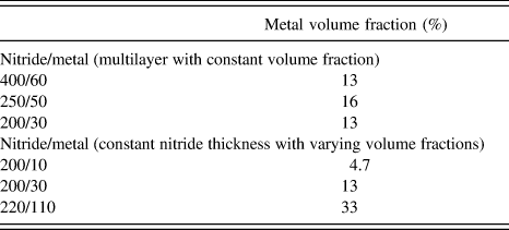
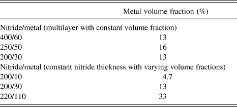
Two important parameters strongly influencing the mechanical properties of the multilayer are volume fraction and bilayer spacing. To uncouple them, a range of selective thicknesses and volume fractions was chosen for the FEM calculations. To study the influence of the volume fraction, the nitride thickness was maintained constant and the metal layer thickness was varied. Another set of configuration maintained the volume fraction by changing nitride/metal layer thicknesses. These sets were chosen to include some experimental data point so that the model could be verified by the experimental results (Table I). Residual stresses were measured from the difference in beam curvature before and after deposition.
Different combinations of metal/nitride with their respective volume fractions used for FEM calculations.
III. RESULTS AND DISCUSSION
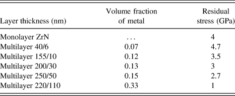
The FEM model was validated by comparing load–displacement curves at low loads with experiments. As seen in Fig. 1, good correlation was noticed till 400 nm after which deviation starts. This deviation might be associated with cracking in the coating, which is not incorporated in the FEM model. This deviation might also be influenced by the simplified assumption of using a spherical indenter of a similar tip radius as that of Vickers in the simulation (50 nm). However, good correspondence at the lower loads provides confidence in the FEM predictions of stresses that will be used later. The residual stresses measured increased more or less monotonically with metal layer thickness and volume fraction from 1 GPa for the 220/110-nm coatings to 4.7 GPa for the 40/6-nm coatings (Table II).
Comparison of FEM and experimental data for spherical indentation on the 250/50-nm multilayer.

Residual stress variation for different metal layer spacings and volume fractions.
A. Critical load for edge cracking
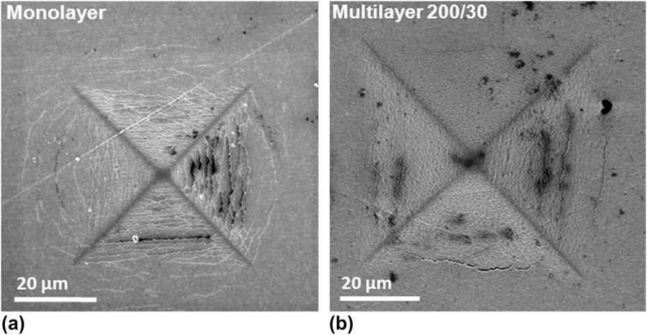
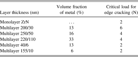
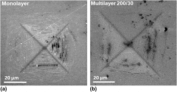
The mode I edge cracking which is visible through the plan view of indents, without any cross sectioning, has been used to gauge the fracture resistance of the film.Reference Suresh, Math, Jayaram and Biswas34 It is similar in origin to the cone cracks that form in monolithic ceramics and, in hard coatings, forms due to elastic bending of the nitride coating at the edge of the indent on a plastically deforming substrate. From Fig. 2, which reveals the plan view of indents for monolayer and 200/30-nm multilayer configurations done at the same load (6 N), it is seen that the extent of edge cracking is larger for the monolayer and the numbers of edge cracks appearing in the monolayer are more compared to the multilayer. Table III indicates the critical load for edge cracking for different multilayer configurations. It clearly indicates that the critical load for edge cracking decreases beyond as well as below the critical thickness of metal, ∼30 nm. It is clear from Table III that the multilayer shows an increase in the critical load for edge cracking with a decrease in the metal layer thickness and the volume fraction except for the layer thickness below 10 nm. Multilayers having low thicknesses of metal, <10 nm, again behave like a monolithic nitride coating with a low threshold for edge cracking. As is shown later, the critical thickness for maximum crack resistance can be understood with respect to the tensile stresses induced in the nitride by a plastically stretching metal on the one hand and, on the other, at very low film thicknesses.
Top-view FIB image of the indent for (a) monolayer and (b) multilayer (with 30-nm metal layer). For the same load, the multilayer shows fewer edge cracks compared to the monolayer.
Critical load for edge cracking for different volume fractions and metal layer thicknesses.
B. Cracking morphology and pattern for different metal layer thicknesses
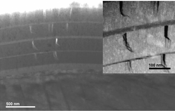
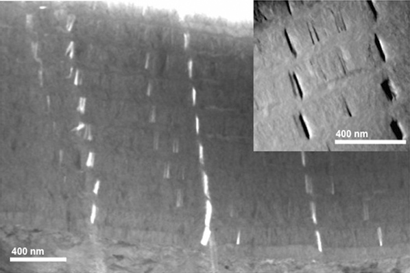
The pattern of cracking in different multilayers is shown in Figs. 3–6. Cracks in the nitride are always restricted within individual layers, i.e., they do not extend into the metal. For 200/50 nm, the cracks propagate half the thickness and deviate, whereas for 220/110 nm, the crack reaches another metal/nitride interface and has a wider opening relative to the 200/50-nm multilayer (Figs. 3 and 4). The distribution of cracking is not homogeneous across the thickness: more cracks are seen near the free surface than near the interface with the substrate (Fig. 3).
Cross-sectional view of the indent (for metal layer thickness ∼ 50 nm) showing more cracks near contact compared to the bottom interface. The high angle annular dark field (HAADF) image in the inset shows branching of cracks approaching the metal nitride interface.
Bright field (BF) image of the indent (for metal layer thickness ∼ 110 nm) illustrates that cracks nucleate at each interface and then remain constrained within the nitride layer. The HAADF image in the inset shows magnified view of cracks with equal crack opening at both the interfaces.
HAADF image of 250/50-nm multilayer. (a) Metal layer outside indent (undeformed) and (b) deformed metal layer showing shear steps (highlighted by arrows) to accommodate the bending strain along with (c) schematic to show the layer shearing. (d) The plastic deformation inside the metal (enclosed in a circle) for 220/110-nm multilayer.
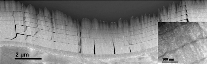
Cross-sectional view of the indent showing interfacial delamination along with edge cracking for metal layer thickness ∼10 nm. The magnified image in the inset shows the presence of curved interfaces.
Metal layers between the nitride show shear sliding in the case of 50 nm, whereas in 110 nm, only traces of plastic deformation are seen (Fig. 5). This implies that the nitride in 50-nm multilayers slides in contrast to the 110-nm multilayer, wherein the metal deforms plastically without nitride sliding. Cracks appear to lie straight along column boundaries in the case of 110-nm layers (Fig. 5). Reducing the metal layer thickness to <10 nm initiates delamination at the interface (Fig. 6).
C. FEM results
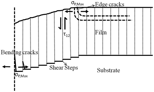
The stresses, which will be discussed in this section, include the maximum first principal stress that nucleates edge and bending cracks as well as the shear stress that is responsible for columnar shear sliding. The location for all cracking and the driving stresses are illustrated in Fig. 7.
Schematic for illustration of different damage modes present in nitride coating under contact loading specifying their locations and concerned stress fields responsible for the origin of these cracks (from Ref. Reference Bhowmick, Kale, Jayaram and Biswas35).
Since the dominant deformation mode in these coatings is columnar shear and edge/radial cracking (microcracking), the maximum principal stress at the edge of the indentation and at each interface, which is responsible for microcracking, as well as the vertical shear stress (τxy) which is responsible for columnar sliding, will be compared in the various films to get the influence of different variables on cracking.
1. Effect of volume fraction and bilayer spacing
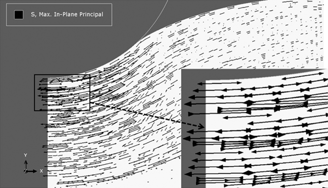
We now examine the variation of the first principal stress and its effect on the distribution of damage throughout the coating. The directions of principal stress are denoted in Fig. 8, where it is seen from the schematic that the stress direction in the nitride is always parallel to the Zr–ZrN interface. The location of edge cracking, seen in Fig. 7, is near the edge of the indent. The surface profile of principal stress is used to predict the propensity and density of edge cracking in this case [Figs. 9(a) and 9(b)]. Clearly, the tensile stress is higher and spread over a wider length in the case of the multilayer compared to the monolayer. The surface profile curves for the maximum tensile stress show two peaks, one immediately outside the indent and another one as a hump somewhere around 7–8 µm away. A slight offset is seen among the different coatings in the first peak position owing to indenter penetration depths with varying metal yield strengths. The first peak is the highest in the case of the 110-nm metal layer multilayer and remains high for a length of 8–9 µm. Both the peak heights scale with the metal layer thickness, but the first peak is more strongly influenced by the metal as seen in Fig. 9(a). It is maximum for the 110 nm followed by the 30 nm and lowest for the 10 nm. The two peaks in tensile stress for the nitride can be related to strain incompatibility between the elastic nitride and plasticity, both in the Zr as well as in the substrate, superimposed on the usual Hertzian stress field. Larger metal thickness leads to greater mismatch (owing both to volume fraction and Hall–Petch weakening effects) in ZrN.
Principal stress direction vector and magnitude denoted by length at different positions inside 250/50-nm multilayer coating. The inset taken from the center of the indent shows the tension in nitride and compression in metal (inverted arrow).
Profile of σP,max at the surface for multilayers with similar nitride layer thicknesses (a), varying volume fractions, and monolayer and (b) with constant volume fraction, varying thicknesses, and monolayer. Note the much wider zone of high tension in multilayers.
For constant volume fraction, the second peak remains the same for all coatings, whereas the first peak scales with the metal layer thickness [Fig. 9(b)]. This implies that the second peak is due to the volume fraction contribution on the coating compliance, whereas the first is due to the metal layer thickness. So the constant volume fraction keeps the stress distribution more or less similar except at the very edge of contact, whereas increasing the metal layer thickness enhances the stress over a larger lateral width. Thus, with an optimum volume fraction, thin metal coatings would be desirable to provide more crack resistance. Experimental validation of this prediction has already been shown for different metal layer thicknesses.Reference Verma and Jayaram26
2. Crack patterns across coating thickness
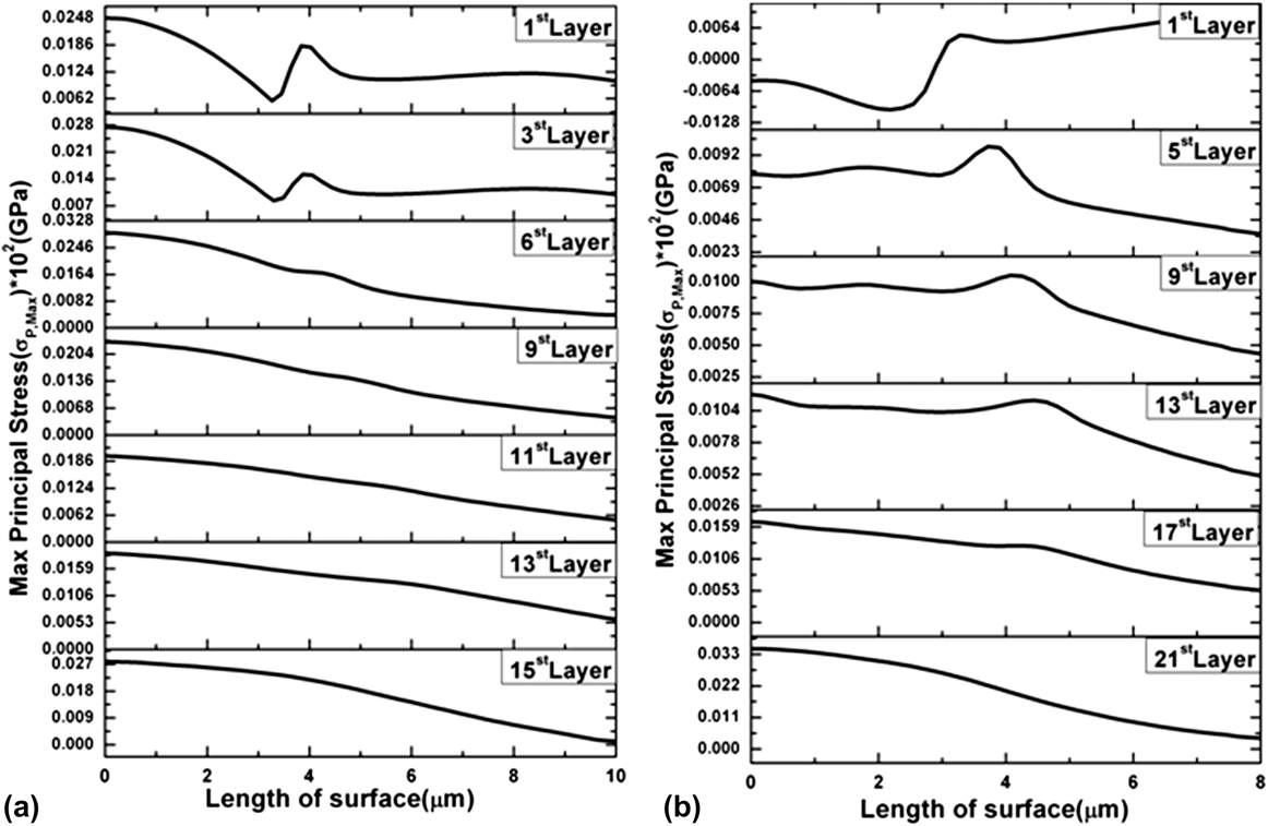
The stress profile was taken inside nitride layers at a regular interval to establish the principal stress variation with respect to depth as shown in Fig. 10(a) for 220/110 and Fig. 10(b) for 200/30 nm. The profiling was done only for two cases for illustrative purpose as the trend in all cases is assumed to be similar. The profiles shown in Fig. 10 clearly show that the stress peaks over a wide spread length at the edge of the indent near the free surface, but as we move toward the substrate, the stress peak shift toward the center. This is a common feature among all the different multilayers (220/110 and 200/30).
Profile of principal stress inside different nitride layers starting from free surface till interface. 1st layer is the topmost layer, and then subsequent nitride layers were taken to profile the principal stress, see the drop near edge and increase in stress near the center of the indent as we move toward the substrate. Figure 12(a) shows profiles of 220/110-nm multilayer and Fig. 12(b) for 200/30-nm multilayer.
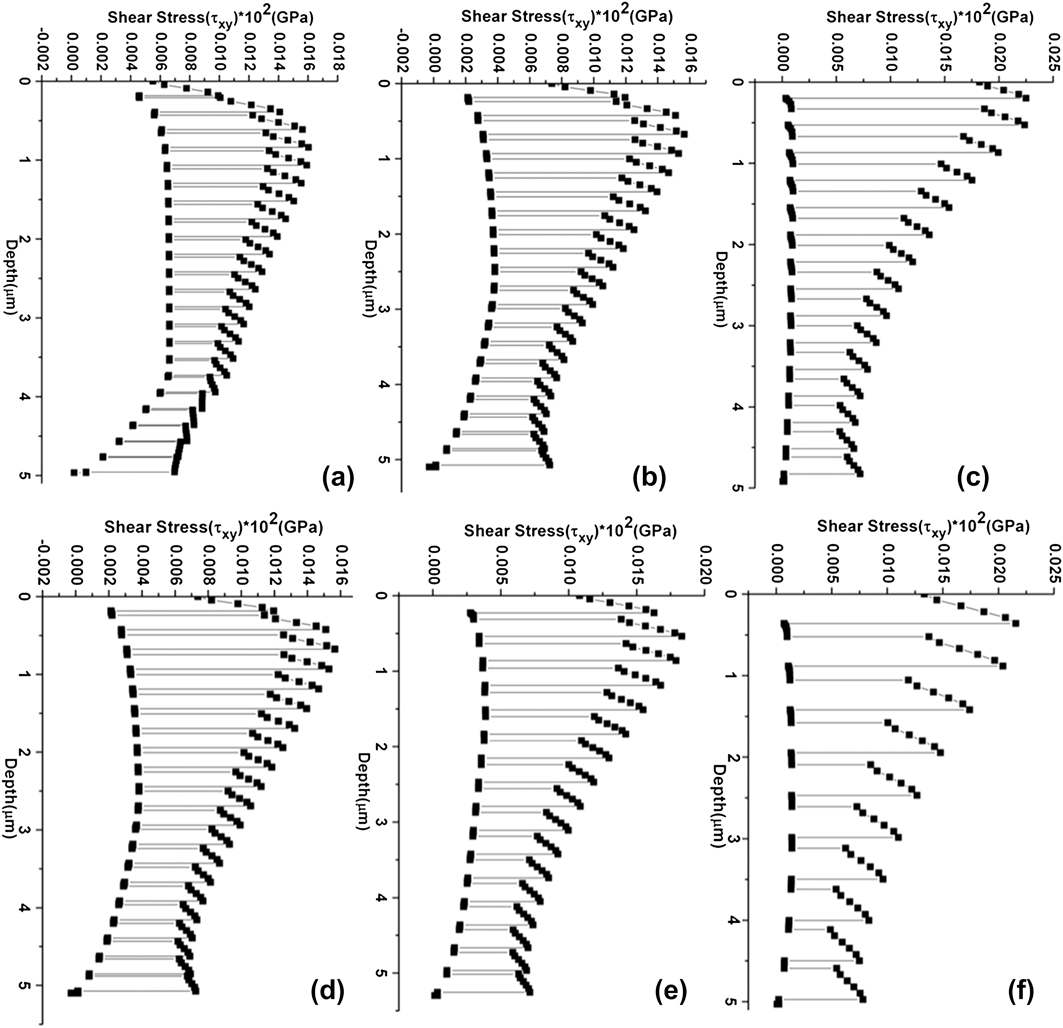
The shear stress in the multilayer is always lower relative to the monolayer as seen from the stress profiles across thickness shown in Figs. 11 and 12. The shear stress peaks somewhere near the edge of the indent, ∼1 µm below the free surface (Fig. 11). In multilayers, the shear stress varies within individual layers (Fig. 12). The major part of the shear stress resides in the nitride for the thick metal layer multilayer, while the metal takes up a much lower value. The shear stress in the metal scales inversely with the metal thickness as can be seen from Fig. 12, in which the highest value is achieved for the 10-nm thick metal layer. The shear stress in the metal remains high over a large depth for thin Zr multilayers. For example, in the case of 10-nm Zr, the shear stress starts dropping at depth ∼4 µm, for 50 nm at ∼3 µm, and for 50 nm, it is within ∼1 µm of Zr layer in the coating. The high shear stress supported by a thin metal layer is a direct consequence of the Hall–Petch model used for the yield stress of Zr. Thus, the combination of wide lateral extent of high tensile (radial) stress and high shear stress near the surface suggests that the cracking/sliding in multilayers will be more distributed at the edge of the indent near the free surface. And due to the drop in stress values near the substrate, the surface-nucleated cracks would converge into fewer cracks, which fully agrees with experimental findings (Fig. 3).
Variation of τxy with respect to depth at radial position, where the shear stress is maximum (under indent) for monolayer (red color) superimposed with a weighted average of shear stress in 220/110-nm multilayer.
Variation of τxy with respect to depth at radial position, where the shear stress is maximum (under indent) for (a) 200/10, (b) 200/30, (c) 220/110, (d) 200/30, (e) 250/50, and (f) 400/70.
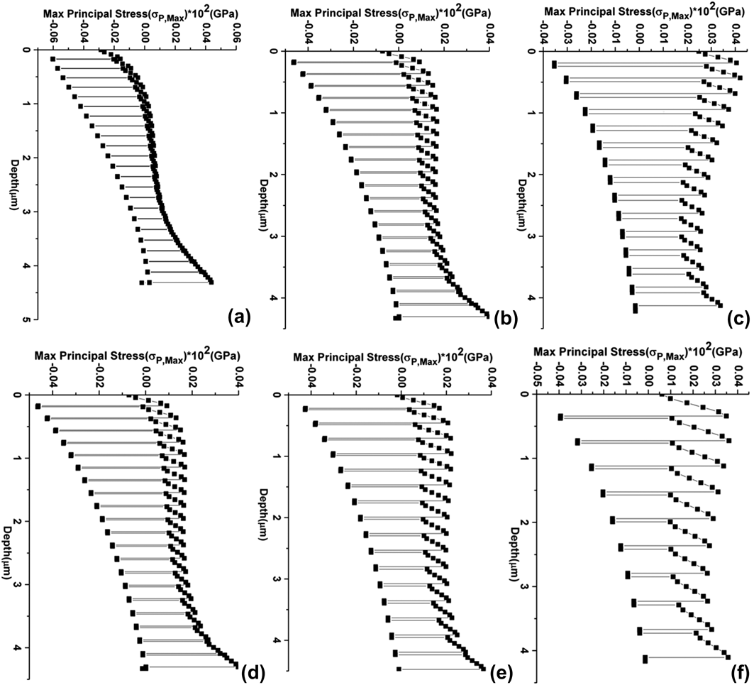
From Fig. 13, it can be seen that the coating with 110-nm metal layer shows tension even immediately under contact [Fig. 13(c)]. The trend in the tensile stress is similar in all cases: the lower interface always experiences higher tension compared to the upper interface for all multilayers with the same nitride layer thickness. More tensile stress gets concentrated under contact for thick metal multilayer (110 nm)/higher volume fraction [Figs. 13(c) and 13(f)], whereas in all other cases, the tensile stress peaks near the substrate. The difference between the maximum and the minimum tensile stress in a given nitride layer goes on reducing with the metal layer thickness; when the metal volume fraction becomes small, one also expects minimal stress enhancement in the nitride due to metal plasticity. For constant volume fraction [Figs. 13(d)–13(f)], the profile of maximum principal stress remains almost the same for different configurations with a small tension in the nitride under the contact for 70-nm metal layers. Notice the fact that the principal stress value within individual nitride layers remains highly tensile for the thicker metal multilayers (70 and 110 nm) explains why we see widely open cracks throughout the nitride layer in the case of 110-nm multilayers (Fig. 4).
Variation of σP,max with respect to depth at r/a = 0 (under indent) for (a) 200/10, (b) 200/30, (c) 220/110, (d) 200/30, (e) 250/50, and (f) 400/70.
The coating with a metal layer thickness of 50 nm shows a similar distribution of cracking throughout the coating, except that the cracks branch out before they reach the opposite interface (Fig. 3). While termination of the crack within the layer may be attributed to the reduction in stress as described earlier, the branching might possibly be a consequence of the in-plane compressive residual stress which is known to lead to crack kinking.Reference Hoek and Bienawsky36
3. Shear stress and sliding
The higher shear strength of the metal with layer refinement also explains why we see shearing of the nitride being transmitted into the metal for 50-nm metal in contrast to the softer 110-nm multilayer, where large plastic strains in the metal appear to trigger crack nucleation in the nitride (Fig. 5). The variation in shear stress across the film thickness also sheds light on earlier observationsReference Xie, Hoffman, Munroe, Singh, Bendavid and Martin12 of how column tilting is restricted to the top column of a multilayer, i.e., the metal seems to shield the lower part of the coating near the substrate from the shear stresses induced by the applied load. This effect is seen in Figs. 11 and 12, which show the effect of metal on the way in which the shear stress in ZrN changes through the thickness. Not only is the magnitude of the shear stress in the film interior reduced but also it can be seen by comparing Figs. 12(d) and 12(f) that as the bilayer period increases at a fixed volume fraction, the shear stress at any depth is a smaller fraction of the peak stress seen in the first layer. Thus, for the case of just a few layers, as in Ref. Reference Xie, Hoffman, Munroe, Singh, Bendavid and Martin12, the major part of sliding would be seen at the top.
We close with a comment on the influence of residual stress. Because of the uncertainty in the way it is partitioned between the two phases, the average stress measured by the curvature cannot be directly incorporated into the FEM analysis. X-ray diffraction can be an answer, but in the present instance, the solubility of nitrogen in Zr and the possibility of stoichiometry variations in the nitride make it difficult to establish standards. The conventional psi-squared method could not be used because of the small film thickness and texture. Biaxial residual stresses will alter the yield criterion in the metal and, more importantly, influence fracture criteria in the nitride. Curvature measurements indicate that the overall compressive stress varies from 1 GPa for the 220/110 multilayer to 4.7 GPa for the 40/6 multilayer, i.e., the thicker and greater the volume fraction of the metal, the smaller is the stress, as expected from the relaxation afforded by plasticity in the metal.
However, it is likely that most of this compression resides in ZrN, where it would act as an inhibiting factor in cracking. Bearing in mind that the compressive stress decreases with thicker metal layers and higher volume fraction of metal, it is clear that the trends in tensile cracking with metal content would be the same as predicted from the role of the applied load, i.e., nitride separated by thicker metal layers would be even more prone to crack, both at the interface with the metal or at the free surface outside the contact.
IV. SUMMARY
FEM was able to rationalize the deformation map for metal/nitride multilayer coating with varying metal volume fractions and bilayer spacings. The metal layer thickness, through its influence on the yield stress, was seen to play a major role in deciding the damage behavior for metal/nitride multilayer coatings. Plasticity in the metal was shown to reduce the shear stress that drives column sliding and increase the radial tensile stress inside the nitride, thereby leading to an increasing crack density for thick metal multilayers. The role of metal layer thickness is similar to that seen in the influence of the properties of the substrate with monolithic coatings of TiN reported elsewhere; here too, soft substrates promote fracture through the stresses induced in the nitride owing to incompatible deformation.
For the present system of ZrN–Zr, a volume fraction of 13% and 30-nm Zr layers were found to minimize cracking. The beneficial role of diminishing metal thickness is abruptly terminated at ∼10 nm below which the ZrN–Zr interface loses planarity, promoting interfacial delamination.