I. INTRODUCTION
Since the beginning of the nuclear age, radiation damage has been a major concern in respect of any material and structure exposed to the radiation environment. It was established that radiation causes a wide range of fundamental materials property changes in materials based on initial knock-on cascades and the subsequent development of extended defects.Reference Kinchin and Pease1–Reference Singh and Zinkle7 Moreover, chemistry changes based on nuclear reactions (e.g., transmutation), volume increase (swelling), and microstructural changes are also of concern. In particular, mechanical property changes such as embrittlement and hardening are a danger to any structure deployed in a nuclear system, in view of the fact that for an embrittled material the basic engineering concept of “leak before break” is often not fulfilled and the accident tolerance is reduced.Reference Hosemann8 As in any material, fundamental changes of the microstructural defects contribute significantly to these mechanical changes. Depending on the material, irradiation dose, and radiation condition, a wide range of extended defects can be created. Those caused by atomic displacements at a given temperature are mainly responsible for an increase in hardening,Reference Azevedo9 yield strength (YS),Reference Byun and Farrell10 ultimate tensile strength (UTS),Reference Maloy, Romero, James and Dai5 and ductile-to-brittle transition temperature (DBTT).Reference Lucas and Gelles11 Moreover, a reduction of total and uniform elongation, upper shelf energy, and fracture toughness is commonly observed. Most early radiation damage studies were conducted in an actual reactor environment, where the dose a material receives is measured in neutron flux [n/(cm2 s)]. This, however, makes it difficult to compare different neutron spectra and assorted radiation sources to be evaluated on a common basis. Therefore, the dose unit of displacements per atom (dpa), initially based on the Kinchin–Pease modelReference Kinchin and Pease1 was found to be more useful and is widely accepted today for facilitating cross comparison among various radiation sources. However, electrical resistivity measurements performed during post irradiation annealing clearly showed a defect evolution,Reference Olander12 which leads to extended defects influencing the mechanical property changes on top of the original displacement damage. The dose unit dpa falls short in describing these post displacement recombination events. Therefore, it is important to include information on the species that created the displacement damage (ion type, neutrons, etc.), the particle energy, and the irradiation conditions such as temperature and dose rate. It is essential to evaluate radiation-induced changes of structural materials not only from an engineering point of view, but also from a basic theoretical scientific point of view in terms of the specific interaction between dislocations and irradiation defects in a quantitative mannerReference Matsukawa, Briceno and Robertson13–Reference Wei, Li, Mara, Nastasi and Misra15 for gaining fundamental insights into basic phenomena such as size effects in mechanical properties and plasticity of irradiated materials in general.
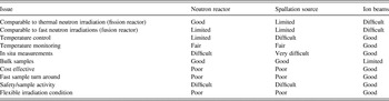
At present, several methods are available for inducing radiation damage, leading to high densities of extended defects such as Frank loops, stacking fault tetrahedra, or voids. Additionally, He bubbles are created when an (n,α) reaction occurs or He is implanted. The main concern of mechanical property changes caused by irradiation applies not only to reactor and spallation source facilities with respect to their structural integrity, but also other applications such as beam windows in medical isotope production accelerators or potential fusion applications. Whereas a material can be exposed in the actual environment such as a reactor or spallation source, displacement damage can also be caused by ion-beam irradiation using any type of charged particle. Importantly, differences between the types of irradiation must be accounted for such as the kind of particle used to cause the displacement damage, irradiation temperature, damage production rate, etc.Reference Was, Busby, Allen, Kenik, Jensson, Bruemmer, Gan, Edwards, Scott and Andreson16 Reactor or spallation source irradiations using neutrons can penetrate through large amounts of material, causing defects in a significant volume. However, this usually happens at a rather low dose rate (up to 20 dpa/year) and at the same time activation of the material in question occurs. Ion-beam irradiations can introduce very high dose rates (>100 dpa/day), and usually do not activate the material if the energy is chosen below the ion-target interaction Coulomb barrier.Reference Was, Busby, Allen, Kenik, Jensson, Bruemmer, Gan, Edwards, Scott and Andreson16 However, ion beams only probe a limited penetration depth. Table I provides a comparison of different irradiation sources causing significant displacement damage (electron- and photon irradiation are therefore not included). We also list issues such as accessibility for in situ measurements and temperature control, as well as qualitatively evaluate the sample irradiation time and costs for a typical experiment attempting a comprehensive overview. While being only a qualitative comparison, it can be seen that ion beams generally offer good control of experimental conditions and accumulate dose over short time periods.
Assessment of various irradiation options with a qualitative statement regarding their benefits and disadvantages.

The good accessibility of ion-beam accelerators and the fact that samples are not activated at low enough ion energies leads to a widespread use of ion-beam irradiation studies to evaluate radiation damage in materials for nuclear energy applications. The acknowledged shortcoming of the limited penetration depth of ion-beam irradiations leads to the need for small-scale materials evaluation methods. Moreover, due to sample activation in reactor irradiations and the frequently limited amount of archived irradiated samples available, small-scale testing approaches are desirable for mechanical evaluation of neutron-irradiated materials as well.Reference Hosemann, Dai, Stergar, Leitner, Olivas, Nelson and Maloy17, Reference Hosemann, Stergar, Peng, Dai, Maloy, Pouchon, Shiba, Hamaguchi and Leitner18 As a significant fraction of experimental costs arises from the post irradiation examination in hot cell facilities, significant cost savings could be achieved by working with small enough samples so that they can be handled in less expensive facilities.
In the field of small-scale testing, distinct progress was made with the development of microhardness measurements and instrumented microhardness testing (nanoindentation).Reference Oliver and Pharr19 With the recent introduction of focused ion-beam (FIB)-based processing, samples can be shaped with sizes in the range of several tens of μm down to several tens of nm, enabling advanced techniques such as microcompressionReference Uchic, Dimiduk, Florando and Nix20 or microtensile testingReference Kiener, Grosinger, Dehm and Pippan21 that can also be performed in situ using electron microscopes.Reference Legros, Gianola and Motz22–Reference Kiener and Minor24 The combination of small-scale mechanical testing and ion-beam irradiation has become a powerful tool for evaluation of the irradiation-induced mechanical property changes and also for the study of the basic mechanisms of deformation-induced interaction between well-characterized irradiation defects and moving dislocations. It is the aim of this work to critically evaluate different small-scale testing approaches for ion-beam-irradiated materials, aiming for a minimum of size effects occurring for obtaining data that can be quantified in a straightforward manner. Furthermore, we will discuss the minimum sample size that can be produced by FIB methods to extract changes of bulk properties. To exclude complications from microstructural features such as grain boundaries or segregation phenomena, single crystal copper (Cu) was chosen as a model material for this study.
II. EXPERIMENTAL
A. Material irradiation and post irradiation testing
In this work protons (hydrogen, H+) were chosen to cause the displacement damage due to their general availability, the comparably large penetration in Cu (up to several μm) compared with heavy ions, and the fact that other ions can lead to unintended implantation effects and potential chemical incompatibility (Table I). The accelerators at Los Alamos National Laboratory’s (LANL) Ion Beam Materials Laboratory (IBML) were utilized for this experiment. Three different irradiation campaigns were conducted on single crystal Cu with either a (100) or (110) out of plane direction. In the following, the experimental details of all three irradiations and their post irradiation examination are given.
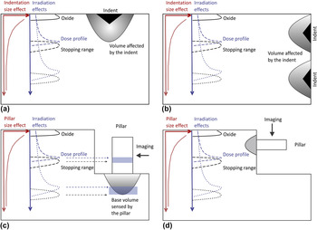
(i) A piece of single crystal Cu was oriented along the (110) axis to perform a shallow irradiation with a 200 keV proton beam using a Danphysik ion implanter. Prior to irradiation, the sample was electropolished to ensure good surface condition, and then mounted on a large Cu block as a heat sink using silver paste to ensure good thermal conductivity. A thermocouple was mounted on the sample to monitor the temperature during irradiation, and the temperature did not exceed 80 °C during the irradiation. For such irradiation conditions the computer software ‘Stopping Range of Ions in Matter’ (SRIM) calculations predict a Bragg peak at ∼1 μm depth.Reference Ziegler, Biersack and Littmark25 Details of the irradiation experiment can be found in Ref. Reference Hosemann, Kiener, Wang and Maloy26. After irradiation, the mechanical properties were examined by nanoindentation at room temperature. The sample was indented onto the surface along the same direction as the ion-beam irradiation utilizing an Agilent nanoindenter (Agilent, Santa Clara, CA) in the quasistatic mode [Fig. 1(a)].
(ii) A 1.3 MeV proton beam from a 3 MV tandem accelerator was used to irradiate another sample of the bulk Cu single crystal along the (110) axis at room temperature. Again, the monitored sample temperature did not exceed 80 °C. The proton beam penetrated 9.8 μm into the material, see Fig. 3(b) and related discussion. After irradiation, the sample was cut in cross section along the (110) axis and mechanically polished. The final step was vibratory polishing using colloidal silica. Electropolishing of the specimen was dropped as an option as sharp edges and a flat near edge region is essential for a successful cross-section nanoindentation experiment close to the implanted surface [Fig. 1(b)]. Subsequently, the sample was indented perpendicular to the ion-beam direction using a Hysitron TriboIndenter 950 (Hysitron, Minneapolis, MN) at the Center for Integrated Nanotechnology (CINT) at LANL. An array of displacement-controlled 200 nm deep indents was performed, always seven indents in a row, with the rows having varying distances from the implanted surface, thereby probing the depth dependence of irradiation-induced hardness changes as introduced previously.Reference Hosemann, Swadener, Kiener, Was, Maloy and Li27 The individual indents were spaced 4 μm apart from each other to avoid any potential interaction between plastic zones from indent to indent. A two-dimensional hardness map in the irradiation direction was established using this technique. After indentation, transmission electron microscopy (TEM) foils were prepared at the exact same locations of the indents by FIB lift-out utilizing a Helios FIB (FEI, Hillsboro, OR). Careful FIB-thinning and a final sample cleaning using a 2 keV Ga+ ion beam enabled to manufacture TEM samples of the actual indent cross sections.
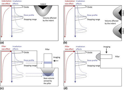
FIG. 1.Schematic depictions of experimental geometries during micromechanical testing for shallow (dashed line) and deep (dotted line) ion-beam-irradiated samples. (a) Indentation performed parallel to the incoming beam. (b) Cross-sectional indentation (i.e., beam perpendicular to the subsequent indentation). (c) Conventional microcompression testing in the ion-beam direction. (d) Cross-sectional microcompression sample geometry of an ion-beam-irradiated sample.

(iii) A (100) oriented Cu wedge was mechanically and chemically thinned, subsequently FIB-machined to a foil with a thickness of 5 μm, and then irradiated with 1.1 MeV protons at room temperature as described in Ref. Reference Kiener, Hosemann, Maloy and Minor28. The ion energy was sufficiently high that the proton-stopping region is not within the sample. Thus, the total dose in the region of subsequent mechanical testing was ∼1 dpa. After ion irradiation, nanopillars with sizes from ∼80 to 2000 nm were FIB-manufactured. These pillars were subsequently compressed in situ in a JEOL 3010 TEM (JEOL, Tokyo, Japan) operating at 300 keV utilizing a Hysitron Picoindenter PI-95 with a Perfomech controller at the National Center for Electron Microscopy at the Lawrence Berkeley National Laboratory. During the feedback-enabled displacement-controlled tests, the sample deformation was continuously monitored.Reference Kiener, Hosemann, Maloy and Minor28

B. Nanoindentation testing
Performing nanoindentation experimentsReference Oliver and Pharr19 on or into the irradiated sample surface in the same direction as the ion-beam irradiation is a straightforward task to do, but it also represents a fairly complicated situation in terms of interpreting the results [see Fig. 1(a)]. While being a highly sensitive qualitative tool for assessing any change of materials properties, e.g., due to the ion irradiation, it requires rather sophisticated analysis before validly extrapolating macroscopic properties such as yield strength and work hardening rate based on a nanoindentation measurement. In fact, one has to be particularly careful with the data evaluation, as a range of effects can contribute to the actual data obtained.
In the following, we discuss the concerns related to perpendicular and cross-sectional nanoindentation as illustrated in Figs. 1(a) and 1(b), respectively.
1. Dose profile
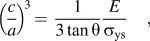
Maybe the most obvious and also the most critical effect of performing irradiations using ions is the inhomogeneous dose (and accordingly the damage) profile beneath the surface. As illustrated in Fig. 1 and well established by Monte Carlo simulations (e.g., group of computer programs which calculate interaction of ions in matter such as SRIM),Reference Ziegler, Biersack and Littmark25 low-energy ion irradiation or heavy ion-beam irradiation generally produces an inhomogeneous dose profile. Small penetration depths or the use of heavy ionsReference Was, Busby, Allen, Kenik, Jensson, Bruemmer, Gan, Edwards, Scott and Andreson16 lead to a less homogeneous dose profile, whereas higher energy ions allow a more flat dose profile deep into the material. Thus, by performing indentations into the sample surface in the beam direction, the material properties are sampled over a wide dose range in a nonuniformly averaged manner. The fact that the plastic zone is in general much larger than the indent itself, see, e.g.,Reference Johnson29–Reference Minor, Asif, Shan, Stach, Cyrankowski, Wyrobek and Warren34 leads to the conclusion that even shallow indents can sample a wide range of dose and dose rates once the irradiation depth is small compared with the deformed area. For a 200-nm deep indent, taking the plastic zone typically five times the indentation depth,Reference Fischer-Cripps35 material to a depth of ∼1 μm is sampled and contributes to the measured hardness. Thus, the hardness measurement convolutes over the entire dose range within this 1 μm depth. This situation does not allow one to associate a particular hardness measurement with a specific dose, but only to state that for instance an increased hardness is measured due to the ion-beam irradiation within a certain dose range. The effect is less dramatic for hard materials, which exhibit smaller plastic zones compared with softer materials according to Johnson’s model,Reference Johnson29 as expressed by:
 $$\left( {{c \over a}} \right)^{\!3} \, = \,{1 \over {3\tan {\rm{\theta }}}}{E \over {{\rm{\sigma }}_{\rm{ys}} }}\quad,$$
where c is the size of the plastic zone, a the radius of the imprint, E the Young’s modulus, σys the yield strength, and θ the semiapical angle of a conical indenter. Equation (1) shows that a material with increased yield strength (e.g., due to irradiation hardening) will have a smaller plastic zone if all other parameters are kept constant.
Shallow ion-beam irradiation causes hardness changes in the near-surface areas whereas the underlying material remains unaffected. This factor is not considered in standard nanoindentation, but can be treated in a similar manner as indentations into thin hard films on softer substrates.Reference Burnett and Page36–Reference Burnett and Rickerby39 These approaches take into account the volumetric contribution of the softer underlying material in the plastic zone. However, mapping of crystal rotations underneath the indents in single crystals by electron backscatter diffraction showed that the extension of the plastic zone is correlated with crystallographic directionsReference Kiener, Pippan, Motz and Kreuzer31, Reference Rester, Motz and Pippan32, Reference McLaughlin and Clegg40, Reference Zaafarani, Raabe, Singh, Roters and Zaefferer41 and a simple model assuming a spherical plastic zone as applied inReference Hosemann, Kiener, Wang and Maloy26 is only a first order approximation.
2. Indentation size effect
Since the first report by Schulze and Hanemann,Reference Nix and Gao42 it is known that smaller indents give higher readings in hardness compared with a macroscopic indent. This effect becomes particularly strong in nanoindentation. Many indentation size-effect (ISE) studies have been performed on various materials to address this issue. Nix and GaoReference Nix and Gao43 discussed a model describing this effect based on the geometrically necessary dislocations required to accommodate the plastic deformation prescribed by the rigid indenter geometry. It was further shown that materials containing a large amount of dislocations (e.g., after deformation) showed less of a size effect than the well-annealed material.Reference Liu and Ngan44
This leads to the general challenge that indenting on the irradiated area of a sample results in different hardness values depending on the indentation depth, just as for any other metal, because of the small-scale nature of the testing technique.Reference Pharr, Herbert and Gao45 This contradicts the desire for shallow indentation depths due to the limited irradiation depth. Further, as the amount of the ISE depends on the defect density, cross comparisons on different material systems and conditions become challenging.
As a general rule, indents should be performed in a displacement-controlled fashion to the same depth to ensure that they are of the same dimension and comparable to one another, as in such a scenario they sample the same material volume. If the indents would be performed in a load-controlled mode, all set to the same maximum load, indents in the harder (irradiated) region will be of shallower depth and therefore appear harder than they really are, resulting in an overestimation of the irradiation-induced hardness increase. This would be of particular concern for cross-sectional indentation experiments and special care should be taken to interpret the results based on the technique chosen.
3. Implantation and surface effects
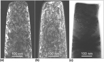
While ion-beam irradiation is performed in vacuum, most samples slightly discolor on the surface in the area of the beam spot, especially if the background pressure is higher than ∼10−6 mbar. Also, if carbon-based mounting material (graphite paste) or similar easy sputtering elements are near the ion-beam rastering area, material can be removed easily and redeposited on unwanted sites such as the sample surface itself. The TEM image in Fig. 2(c) clearly shows that some unwanted deposition or contamination on the sample surface took place in the accelerator for precut nanopillars where silver paste and carbon tape were used for mounting. Whereas the contamination layer can be rather thin and might possibly not affect microhardness measurements [see Fig. 2(c)], it cannot be neglected for very shallow indents typical for nanoindentation.Reference Cordill, Moody and Gerberich46 Therefore, as shallow indents contain the risk of including such contamination or oxidation artifacts, indents of larger depth would be preferable to avoid this issue. This demand, however, can contradict the call for shallow indentation depths required to confine the plastic zone to the irradiated volume.
TEM images of a (100) oriented Cu pillar with a top diameter of 200 nm. (a) Dark-field image after FIB preparation. (b) Dark-field image of the same pillar after proton irradiation. A 12 nm thick surrounding contamination layer and irradiation defects (small black dots) are visible. (c) Bright-field post compression micrograph of the pillar after deformation. The contamination layer detached from the sample in the deformed top part.

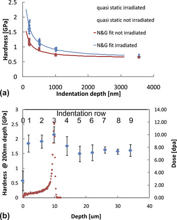
(a) Hardness versus indentation depth plotted for 1 μm deep irradiated and unirradiated Cu. Shallow indents performed in the irradiated part show significantly higher hardness than in the unirradiated region. The solid lines are the Nix and GaoReference Nix and Gao43 fits to the data measured. (b) Results from hardness measurements on the sample cross-section as a function of location from the edge of the specimen (sample surface) for 200 nm deep indents. The SRIM dose profile is given by the red data points, and notably the hardness values track the dose profile. The TEM images in Fig. 4 were taken from indentation rows 3 and 5, respectively.

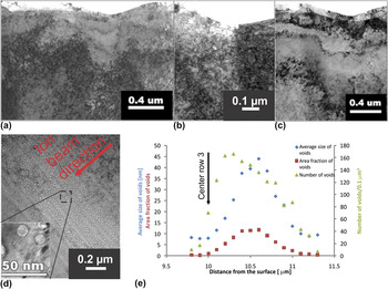
(a) TEM image of an indent cross section. The indent was situated in the Bragg peak region marked as row 3 in Fig. 3(b). (b) TEM image of an indent performed in region 3. The voids underneath the indent are clearly visible due to underfocus imaging conditions. (c) TEM image of an indent cross-section from in the unirradiated region marked as row 5 in Fig. 3(b). (d). TEM image of voids in the Bragg peak region with a higher magnification insert to show the faceted voids. The ion-beam direction is indicated. (e) Statistical analysis of the void distribution shown in (d).

Besides causing surface contamination and displacement damage, the ions used in the ion irradiation are going to stop in the material itself in a subsurface region called the stopping peak and have the potential to: (i) change the local chemistry if not irradiated with self ions, (ii) form bubbles if insoluble gas ion species [e.g., helium (He)] are used, or (iii) act as a source for excessive interstitials which can potentially affect the resulting defect structure. An indentation experiment where the plastic zone extends through the stopping peak region will also sample these effects and lead to different results than what would be measured if either the irradiation depth was deeper or the indentation depth was shallower [Fig. 1(a)].
From these considerations the question arises concerning what is actually sampled in such hardness measurements and how representative such a quantity is. Importantly, because the stopping peak is rather narrow, the beam condition and ion species can be chosen such that these effects might not be as pronounced compared with the effect of varying dose range and the ISE. Depending on the focus of the study, this issue has to be considered for each individual irradiation experiment.
To demonstrate the issues discussed above, a shallow irradiation using irradiation condition 1 and subsequent indentation according to the situation sketched in Fig. 1(a) as well as a deep irradiation using irradiation condition 2 in combination with cross-sectional indentation [Fig. 1(b)] will be shown, bringing the attention to the difficult data interpretation when using nanoindentation for such ion-beam-irradiated materials.
C. Micro-/nanocompression
Miniaturized experiments using FIB-based sample fabrication offer the advantage of a nominally uniaxial stress state across the whole sampleReference Uchic, Dimiduk, Florando and Nix20 in comparison to the inherent strain gradient effects associated with nanoindentation experiments.Reference Nix and Gao43 In addition, microcompression allows more site-specific testing than indentation. As the surrounding material is removed, the deformation occurs at a specified location and in a well-defined volume, not in a volume underneath an indent where the plastic zone might not be well known. In particular for materials exposed to shallow irradiation it is essential to know the exact probing location and sampling volume to avoid potential influence from material with a different history. Finally, for a uniaxial test it is a straightforward task to derive the stress—strain curve from the measured load—displacement data, which is much more complicated for the nanoindentation data.
As depicted in Fig. 1(c), for pillar compression in the irradiation direction similar concerns arise as for nanoindentation experiments [Fig. 1(a)]:
1. Dose profile
Depending on the relation between implantation depth and pillar size, different material conditions are probed. In general, the dose profile and corresponding mechanical properties will be inhomogeneous over the pillar height, as indicated for the shallow irradiation profile in Fig. 1(c). Moreover, as the stopping peak is usually within the sample, it does act as a hardened layer. Deformation will localize in the softer material parts, similar to what was observed for multilayers.Reference Singh, Chawla, Tang and Shen47 Moreover, if the stopping peak is close to the sample base [deep irradiation case in Fig. 1(c)], it affects the penetration of the whole sample into the underlying substrate, which is usually accounted for by the Sneddon correctionReference Sneddon48 assuming bulk material properties.
Thus, the samples should preferably be significantly smaller than the irradiation depth and maintain an aspect ratio between diameter and height of ∼1:3Reference Zhang, Schuster, Wei and Ramesh49, Reference Uchic, Shade and Dimiduk50 to minimize for boundary constraints.Reference Kiener, Grosinger, Dehm and Pippan21, Reference Kiener, Motz and Dehm51 Beneficially, besides the simple nominal conversion from load—displacement data to a stress—strain plot, this geometry also allows straightforward in situ observation of the sample deformation.Reference Legros, Gianola and Motz22, Reference Kiener, Motz, Dehm and Pippan52, Reference Michler, Wasmer, Meier, Ostlund and Leifer53 Finally, a top oxide layer or other contaminants of concern that might have formed during irradiation can be removed by FIB-milling from the free standing pillar top. In summary, the microcompression approach in beam direction removes several issues indicated for nanoindentation techniques above, but there remains the possibility of an unwanted dose gradient over the sample height.
Similar to the benefits of cross-sectional nanoindentation over regular (surface) indentation experiments, a cross-sectional geometry in pillar compression as shown in Fig. 1(d) eliminates this last issue.Reference Kiener, Hosemann, Maloy and Minor28 By placing pillars at different irradiation depths, the flow behavior for different irradiation doses can be explored on a single sample. As long as the samples are small with respect to the dose gradient, this gradient should be of minor concern. Moreover, changing the sample size for a given irradiation dose allows to study fundamental aspects such as the transition from size-dependent to size-independent material strength.Reference Kiener, Hosemann, Maloy and Minor28 Finally, as the pillar base consists of the same material as the sample itself, no further complications with the Sneddon correctionReference Sneddon48 or other unwanted pillar sink inReference Ye, Mishra, Pelton and Minor54 arise. As for the perpendicular approach, this cross-sectional geometry is well suited for direct observation during in situ testing.Reference Kiener, Hosemann, Maloy and Minor28
2. Sample size effects
As stated above, in contrast to nanoindentationReference Oliver and Pharr19 there is no global strain gradient involved for microcompression.Reference Uchic, Dimiduk, Florando and Nix20 However, a different kind of size effect was reported, where smaller samples are stronger.Reference Uchic, Dimiduk, Florando and Nix20 This was observed for single crystal samples as large as 80 μmReference Uchic, Shade and Dimiduk50 down to only several tens of nm.Reference Kiener and Minor24 For determining a bulk yield stress for engineering applications from such miniaturized experiments, a transition from this size-dependent strength to bulk properties needs to be explored.Reference Kiener, Hosemann, Maloy and Minor28, Reference Girault, Schneider, Frick and Arzt55 Moreover, as such small-scale tests exhibit some inherent scatter by the limited number of dislocation sources in the sample,Reference Dimiduk, Uchic and Parthasarathy56 the determined bulk strength might be scattered accordingly. Applying emerging methods for massive parallel sample fabrication such as microembossingReference Buzzi, Dietiker, Kunze, Spolenak and Loffler57 or deep reactive ion etchingReference Moser, Wasmer, Barbieri and Michler58 to the irradiated material of interest will in the future help to increase the number of samples tested and thereby improve the sampling statisticsReference Rinaldi, Peralta, Friesen and Sieradzki59 to remove this complication.
It is worth mentioning that, although the loading situation is nominally uniaxial, there are experimentalReference Uchic, Shade and Dimiduk50, Reference Kiener, Motz and Dehm51, Reference Kiener, Guruprasad, Keralavarma, Dehm and Benzerga60, Reference Shade, Wheeler, Choi, Uchic, Dimiduk and Fraser61 and computationalReference Kiener, Guruprasad, Keralavarma, Dehm and Benzerga60–Reference Raabe, Ma and Roters62 evidences that local strain gradients can emerge due to the boundary conditions influencing the deformation behavior. While being beyond the scope of this work, such influences can in the future be mostly eliminated by miniaturized tensile tests.Reference Kiener, Grosinger, Dehm and Pippan21, Reference Kiener and Minor23, Reference Gianola and Eberl63
3. Implantation and surface effects
A TEM image of a single crystal Cu pillar after FIB fabrication is shown in Fig. 2(a). For this pillar geometry, the potential creation of an oxide layer in poor vacuum or redeposition of sputtered material during irradiation will not only affect the sample surface as is the case in the nanoindentation experiment, but the whole specimen surface, as seen from the contamination layer in Figs. 2(b) and 2(c). Therefore, it is recommended to first perform the irradiation experiment and then create the testing samplesReference Kiener, Hosemann, Maloy and Minor28 for avoiding potential issues in a less than perfect vacuum or sputtering situation. With this procedure, the surface oxide only affects the sample top in Fig. 2(b), which is presumably of less concern than in a nanoindentation scenario. A hard surface layer will reduce the deforming volume and might create a dislocation pile-up at the interface between material and oxide. However, it was shown for titanium nitride (TiN)-covered CuReference Kiener, Motz, Schöberl, Jenko and Dehm64 that no significant differences in strength and work hardening were observed.Reference Shade, Wheeler, Choi, Uchic, Dimiduk and Fraser60 The situation will be more complicated once the oxide is porous, forms cracks, etc. However, as outlined before, the oxide layer can be removed from the pillar by FIB-milling, or completely avoided by the cross-sectional approach shown in Fig. 1(d).
A general concern arises from the additional near-surface modifications due to the damage created during FIB-machining [Fig. 2(a)].Reference Kiener, Motz, Rester and Dehm65, Reference Volkert and Minor66 It was shown that for initially defect-free material,Reference Bei, Shim, George, Miller, Herbert and Pharr67 the strength is significantly reduced by the presence of FIB defects.Reference Shim, Bei, Miller, Pharr and George68 However, considering that irradiated material contains extended irradiation defects in the order of 1 × 1024 m−3, Reference Singh and ZinkleRef. 7. Distributed throughout the volume, these surface modification issues are less of a concern than when testing unirradiated samples.Reference Kiener, Hosemann, Maloy and Minor28
III. RESULTS AND DISCUSSION
A. Surface nanoindentation
Figure 3 shows the ISE for a single crystal Cu irradiated to a depth of 1 μm (condition 1) for quasistatic indentations ranging in depth from 200 to 3500 nm. For comparison, the unirradiated material was tested under the same conditions. The increased hardness of the irradiated material for shallow indents (<1000 nm) can be clearly seen compared with the unirradiated case. For example, indents performed in the irradiated sample to a depth of 200 nm show a hardness of 1.60 GPa, which is 430 MPa higher compared with the unirradiated area (1.2 GPa). Indents performed to deeper depths such as 3500 nm show no difference in hardness between the irradiated and unirradiated sample (650 MPa), respectively. When performing a Nix and Gao fitReference Nix and Gao43 for this data to quantify the ISE, the irradiated sample shows a more pronounced ISE than the unirradiated one, as detailed in Reference Hosemann, Kiener, Wang and MaloyRef. 26. This is surprising, as an irradiated sample contains significantly more defects than the unirradiated material, thus a behavior similar to a cold-worked material, which exhibits a less pronounced size effect, could be expected.Reference Liu and Ngan44, Reference McElhaney, Vlassak and Nix69 This contradiction can be explained by acknowledging that, assuming a plastic zone of five times the indentation depth, only indents smaller than 200 nm probe exclusively the irradiated region. Deeper indents sample also the unirradiated region, as supported by the comparable hardness values for deep indents in the unirradiated and irradiated case in Fig. 3.
Therefore, if one is to perform a size effect study on shallow irradiated material, the overlap of ISE and irradiation dose profile does not allow a simple interpretation of such measurements. Utilizing a “rule of mixture” approach, similar to what is done on hard film coatings, enables a more realistic estimate of the materials behavior.Reference Hosemann, Kiener, Wang and Maloy26 However, this is only a first order approximation, as the plastic zone is most likely smaller in an irradiated sample as compared with an unirradiated sample, as will be shown below.
B. Cross section nanoindentation
Figure 3(b) depicts indents performed in cross section on a single crystal Cu sample exposed to a high-energy proton beam as described in irradiation condition 2. Each data point represents the average of seven measurements to a depth of 200 nm, all having the same distance from the original surface. Whereas the first hardness data point is in the embedding mass (indentation row 0), the following data points labeled as indent 1, 2, and 3 are in the irradiated region. Indents following number 4 up to 9 are in the unirradiated material and can be regarded as control measurements. It can be seen that the hardness steadily increases as the dose increases as a function of penetration depth for the first three indents (10 μm deep into the material). Utilizing this cross-sectional indentation method, a specific hardness value can be associated with a rather specific dose [Fig. 3(b)], where the dose range is limited by the size of the plastic zone surrounding the indent. In addition, it is ensured that only irradiated material is sampled without any additional effect from potentially underlying unirradiated material (Fig. 1).
Comparing the hardness values of 1.5–1.6 GPa in the unirradiated region (indents 4–9) from this experiment to the value of 1.84 GPa on the irradiated material (indent 1 with a dose of 1 dpa), we find a hardness increase of 240–340 MPa. It should be noted that the hardness of 1.5–1.6 GPa is comparable to the previously published hardness measurements for indents of the same indentation depth of 200 nm.Reference Rester, Motz and Pippan32, Reference McElhaney, Vlassak and Nix69 The 240–340 MPa hardness increase due to the irradiation treatment is slightly lower than the 430 MPa increase observed in the surface indentation experiments for indents with the same depth of 200 nm described above [Fig. 3(a)]. This slight difference can be explained by either surface contamination or oxidation of the surface-indented sample, or the fact that the indents performed on the surface rather than in cross section do also sample harder material from the underlying Bragg peak. A yield stress estimation from the hardness measurements can be performed utilizing an equation determined for irradiated austenitic stainless steelsReference Busby, Hash and Was70:
 $${\rm{YS}}\,\,{\rm{ =\, }}\,{\rm{0}}{\rm{.31*}}H\quad,$$
with yield stress YS and hardness H in MPa. We find that the hardness increase of 340 MPa on the cross-sectional indentation experiments leads to an increase in YS of ∼105 MPa, whereas the 430 MPa hardness change from the surface indents corresponds to ∼133 MPa increase in YS. Both numbers compare reasonably well to YS data gained from large (>0.8 μm diameter) microcompression experiments, where a YS increase due to irradiation of ∼100 MPa was reported.Reference Kiener, Hosemann, Maloy and Minor28 The rationale for comparing 200 nm deep indents with 0.8 to 1 μm diameter pillars is that the tested volume is rather similar in both cases. A 200 nm deep indent with an assumed spherical plastic zone radius of five times its indentation depth samples a volume of ∼2.1 μm3, whereas a pillar of a diameter of 0.8 μm and length of 5 μm as tested inReference Kiener, Hosemann, Maloy and Minor28 also samples 2.1 μm3 of material.
After indenting the sample in cross section, FIB cross sections were prepared to accurately measure the indent position with respect to the irradiated surface to determine the dosage range. Subsequently, TEM foils were prepared of the cross-sectioned indents to investigate the surrounding microstructure. Figures 4(a)–4(c) present TEM images showing an indent from the irradiated indentation row 3 and the unirradiated row 5, respectively. While the indents are clearly visible, it is obvious that a 50 to 100 nm damaged layer exists on the sample surface, most likely caused by the mechanical polishing performed during preparation of the soft Cu sample. We assume that the higher hardness readings from the cross section experiments (1.5–1.6 GPa) compared with the softer behavior of the surface indents (1.17 GPa) for the unirradiated sample are caused by this damaged layer on the surface. Estimating a plastic zone extending 1 μm around the 200 nm deep indents, we calculate that a 50 to 100 nm thick damaged layer contributes 8–15% to the overall hardness reading when utilizing the rule of mixture.Reference Hosemann, Kiener, Wang and Maloy26
As seen in Figs. 4(c) and 4(d), at the end of the H+ ion range a substantial amount of faceted voids are present, while no voids were observed in the 1 dpa area. Whereas the subject of this study is not the nature and mechanism of void formation in Cu, as this has been widely studied elsewhere,Reference Mukouda, Shimomura, Iiyama, Harada, Katano, Nakazawa, Yamaki and Noda71, Reference Zinkle and Knoll72 the finding is worth reporting. Comprehensive studies performed in the past suggest that the presence of impuritiesReference Shimomura, Mukouda, Zinkle, Lucas, Ewing and Williams73 as well as the nature of the ion-beam irradiation which is conductedReference Westmoreland, Malmberg, Steele and Wolicki74 (beam rastering or broad beam) can have a significant effect on the resulting microstructural features. Due to the fact that only one irradiation with one irradiation parameter was conducted in this work, it is difficult to add to this ongoing discussion. However, we observed that the void size and number density follow a near-Gaussian distribution with a peak position at 10.5 μm depth and a width of 1.5 μm as show in Fig. 4(e). Comparing the SRIM calculations utilizing the “Monolayer Collision steps” mode and a displacement energy Ed = 25 eV it is found that the location of the Bragg peak is at 9.84 μm depth and the H+ implantation peak at 9.96 μm depth.Reference Ziegler, Biersack and Littmark25 Both numbers are slightly shallower in expression of depth than the location of the center of the Gaussian void distribution at 10.5 μm depth. This difference is rather small, and can be attributed to the fact that SRIM assumes a homogeneous distribution of Cu atoms and does not recognize the potential effect of channeling, whereas this irradiation experiment was conducted along the (110) zone axis. The choice of 25 eV for the displacement energy along the (110) axis is supported by reports of Ed = 19–30 eV for accelerator-based experiments and Ed = 25–30 eV for computational analysis, summarized by Kenik and Mitchell for Cu in various orientations.Reference Kenik and Mitchell75 In addition, it has to be noted that the SRIM calculation presented here was conducted in the “Ion distribution and quick calculation of damage” mode which utilizes the Kinchin–Peace model,Reference Kinchin and Pease1 which leads to evaluation of lower value of damage than the value assessed by the “detailed calculation with full damage cascade” model.
It is also worth mentioning that we find a higher number of small voids in an implantation depth of 10.3 μm whereas we find slightly larger but fewer voids at a depth of 10.6 μm [compare green and blue symbols in Fig. 4(e)]. This small difference could be based on the fact that the deeper voids are formed early in the irradiation due to the immediate presence of H+ and can grow during the ongoing irradiation. The smaller voids in the shallower region (∼300 nm closer to the surface) might start to nucleate later in the irradiation process due to the fact that it took time for the H+ to diffuse from the end of the implantation range toward the surface for stabilizing the voids there. This is, however, speculative and could also have other explanations. More experiments at various temperatures and with different diffusion ranges of H+ need to be conducted to clarify this difference in void size and void distribution. It is interesting to note that in Fig. 4(c) voids are still present in the plastic zone directly underneath indent 3 and do not appear to have been disturbed by the deformation. If confirmed by future and more in-depth studies, this behavior correlates well with previous results,Reference Fish, Straalsund, Hunter and Holmes76 where it was found that the shape of the voids could be disturbed, but they cannot be removed. This would be distinctly different from what is observed for stacking fault tetrahedrons, which are generally removed by passing dislocations.Reference Kiener, Hosemann, Maloy and Minor28, Reference Robach, Robertson, Lee and Wirth77, Reference Marian, Martinez, Lee and Wirth78
C. Surface pillar compression
The compression sample shown in Fig. 2(a) was proton-irradiated after FIB fabrication. During irradiation, defects formed as seen by the black dots in Fig. 2(b), and a 12 ± 1 nm thick contamination layer emerged on all surfaces, as can be seen in the TEM image in Fig. 2(b) and more clearly in Fig. 2(c). During compression of the pillar to a plastic strain of 14%, this contamination detached from the deformed areas. Further, on the contact surface the thickness of this layer was reduced in height to 10 ± 1 nm, leading to additional sample compliance. Moreover, any outside layer could hinder dislocations from escaping at the sample surface, leading to the formation of a pile-up as recently reported for example for polyimide on an Al film.Reference Oh, Rentenberger, Im, Motz, Kiener, Karnthaler and Dehm79 In our case, the detachment of the contamination film indicates no strong binding to the Cu pillarReference Kiener, Zhang, Sturm, Cazottes, Imrich, Kirchlechner and Dehm80 and should therefore be of minor concern.
The contamination can be reduced by choosing different materials in the irradiation chamber environment (materials with a lower sputter yield) and by ensuring a better vacuum, but it cannot be entirely excluded. Generally, avoiding possible influences following the cross-sectional approach is preferable and will be shown below.
D. Cross section pillar compression
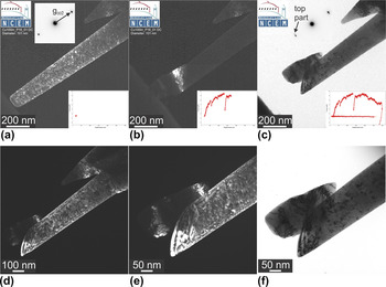
Figure 5 shows TEM micrographs of a proton-irradiated 101 nm diameter Cu(100) pillar before, during, and after in situ compression testing. This sample was prepared in a thin wedge approachReference Kiener, Hosemann, Maloy and Minor28, Reference Moser, Felber, Rashkova, Imrich, Kirchlechner, Grosinger, Motz, Dehm and Kiener81 following Fig. 1(d), and clearly no contamination layer is visible in either bright-field or dark-field images, in contrast to the details seen in Figs. 2(b) and 2(c). As in a previous report,Reference Kiener, Hosemann, Maloy and Minor28 during in situ TEM compression testing we observe that the sample containing numerous defects [Fig. 5(a)] deforms initially in a rather smooth way. Distinct load drops indicating dislocation avalanches as reported for unirradiated Cu using the same testing procedureReference Kiener and Minor24 were absent. Upon further deformation, a pronounced slip localization is formed, clearly indicated by the load drop in the mechanical data in Fig. 5(b) and the emerging slip step. It is also interesting to note that this localization did not occur in the region close to the sample top, where the highest stresses are present, but about 200 nm down the sample height. This indicates that some weak link mechanism controls the localization, not the highest stress. The subsequent apparent softening upon further deformation [Fig. 5(c)] is the result of the decreasing sample cross-section, which is not reflected in the recorded load—displacement data in the inset. Comparison of the diffraction patterns of the sample top areas provided as insets in Figs. 5(a) and 5(c) shows the occurrence of an additional diffraction spot. This results from a slight rotation of the sheared sample top with respect to the rest of the sample during compression. The post deformation images [Figs. 5(d)–5(f)] confirm the presence of numerous crystal defects in the tested sample and the absence of an extended contamination layer.
TEM images of a proton-irradiated (100) oriented Cu pillar with a top diameter of 101 nm. (a) Dark field image showing the highly defective sample microstructure. (b) In situ dark field image after formation of the slip localization. (c, d) Bright and dark field image after unloading. (e, f) Detail of the deformed sample top showing the sharp slip localization in bright and dark field imaging.

Studying differently sized pillars in such a cross section geometry, it was observed that for irradiation condition 3 a transition from a dislocation source-controlled and size-dependent yield strength to a size-independent yield strength of 220–280 MPa governed by the interaction of dislocations with irradiation defects occurred at ∼400 nm diameter in Cu.Reference Kiener, Hosemann, Maloy and Minor28 This agrees with the ∼300 MPa yield strength estimated from nanoindentation experimentsReference Hosemann, Kiener, Wang and Maloy26 and previous bulk tests.Reference Singh and Zinkle7 However, for the current irradiation conditions this transition length scale of ∼400 nm also sets a limit to the achievable miniaturization.
The hardening mechanisms observed in such small single crystal samples typically relate to exhaustion of dislocation sources,Reference Kiener and Minor23, Reference Kiener and Minor24 which is distinctively different from bulk hardening mechanisms governed by dislocation storage. Thus, studying the bulk hardening response can require larger samples that could give rise to dose gradients again. However, this mainly holds for single crystal samples, while for specimens containing several microstructure features across the diameterReference Hosemann, Swadener, Kiener, Was, Maloy and Li27 this should be less of a concern.
IV. CONCLUSION
In this work, a detailed comparison between commonly used small-scale mechanical characterization methods for ion-beam-irradiated samples is presented. We critically revisit the benefits and disadvantages of surface indentation and cross-sectional indentation and demonstrate that cross-sectional indentation is preferable to the conventional surface nanoindentation approach. In addition, the influence of radiation on ISEs and the plastic zone around an indent is depicted, suggesting that a size effect relationship obtained on an unirradiated material cannot be applied directly to an irradiated material, making a comparison between nanoindentation hardness, microhardness, or bulk mechanical uniaxial data not straightforward. It was further shown that miniaturized uniaxial tests, e.g., pillar compression or microtensile testing, offer several benefits over indentation experiments, in particular if they are applied in the cross-sectional approach. The benefits of uniaxial tests are that they: (i) eliminate the dose gradient [Figs. 1(a) and 1(c)]; (ii) eliminate the indentation strain gradientReference Nix and Gao43; (iii) probe a well-defined volume [Figs. 1(b) and 1(d)]; (iv) deliver a stress-strain curve rather than only a hardness value; (v) circumvent contamination issues; and (vi) offer the possibility for in situ observation of the sample deformation, thereby even allowing for a direct determination of the deformation mechanisms.Reference Kiener, Hosemann, Maloy and Minor28 Whereas these are several benefits favoring microcompression, one must not forget that this technique typically requires a substantial amount of sample preparation using FIB approaches, while numerous nanoindents can be performed on a well-prepared surface or cross-section. Therefore, a combination of the two techniques is probably desirable in many situations.
ACKNOWLEDGMENTS
Ion irradiation and nanoindentation work was partially supported by Center for Integrated Nanotechnologies (CINT), a DOE nanoscience center jointly operated by Los Alamos and Sandia National Laboratories. Funding was provided partially by the Berkeley nuclear research center (BNRC), established by the University of California Office of the President and the UC-National Laboratory Fee Research Program as well as by the NRC faculty development grant, NRC-38-09-948. DK gratefully acknowledges financial support of the Austrian Science Fund (FWF) through the project J2834-N20. The in situ TEM experiments were performed at the National Center for Electron Microscopy, Lawrence Berkeley National Laboratory, which is supported by the U.S. Department of Energy under Contract No. DE-AC02-05CH11231.