I. INTRODUCTION
The low rhombohedral symmetry of prototypical multiferroic BiFeO3 often causes complex domain structures, even in bulk crystals.Reference Kubel and Schmid1 A common approach to limit the complexity and open avenues for device realization is through epitaxy, where a well-suited technique to extract the structural details of these engineered epitaxial BiFeO3 thin films is high-resolution x-ray diffraction and reciprocal space mapping (HRXRD-RSM). For BiFeO3, HRXRD-RSM is especially attractive because high crystalline quality epitaxial thin films can be deposited resulting in relatively sharp Bragg reflections.Reference Das, Kim, Baek, Eom, Zavaliche, Yang, Ramesh, Chen, Pan, Ke, Rzchowski and Streiffer2–Reference Wang, Neaton, Zheng, Nagarajan, Ogale, Liu, Viehland, Vaithyanathan, Schlom, Waghmare, Spaldin, Rabe, Wuttig and Ramesh4 Additionally, in comparison with other rhombohedrally distorted perovskite based materials, including LaAlO3 and PbZr1−xTixO3 (x ≈ 0.25), the bulk rhombohedral distortion (α r) in BiFeO3 is relatively large, α r = 89.43°.Reference Bueble, Knorr, Brecht and Schmahl5–Reference Kubel and Schmid7 This causes peaks from different structural domains to exhibit large splitting in reciprocal space increasing accessibility.
Although these advantages exist, certain details of the epitaxial BiFeO3 film structure remain uncovered. In particular, ferroelastic twin walls are known to have unique properties in comparison with the bulk systems.Reference Gopalan, Dierolf and Scrymgeour8–Reference Schilling, Adams, Bowman, Gregg, Catalan and Scott10 However, understanding properties of twin walls in BiFeO3 thin films is still at its infancy.Reference Yang, Seidel, Byrnes, Shafer, Yang, Rossell, Yu, Chu, Scott, Ager, Martin and Ramesh11 In this study, HRXRD-RSM was used to measure the extrinsic distortion of vertical twin walls in (001) BiFeO3. This was achieved by using a basic method to extract structural aspects of the film including (i) epitaxial strain, (ii) domain arrangements, and (iii) lattice rotations; from which, the twin wall distortion was calculated. Interestingly, although coherent twin walls are preferred to minimize strain energy, we demonstrate that semicoherent walls can exist in certain BiFeO3 heterostructures, which exemplifies the importance of film growth kinetics on particular single-crystal substrate surfaces.
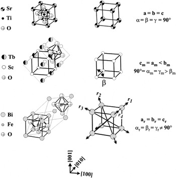
The method developed to analyze the RSM data conveniently describes the BiFeO3 film and substrate with a subcell. The subcells used are illustrated in Fig. 1 for the two substrates chosen, SrTiO3 with the ideal perovskite structure (Pm  m), TbScO3 with the GdFeO3 type structure (Pbnm).Reference Velickov, Kahlenberg, Bertram and Uecker12 In both cases, four atoms are isolated forming the corners of the subcell. Likewise, the bulk unit cell of BiFeO3 (R3c) was treated in the same manner (Fig. 1). It should be noted that information like octahedral tilting was lost by not using the full unit cell description.Reference Glazer13 In this work, the structural details of interest, including extrinsic distortion at vertical twin walls, are sufficiently described within this simplified subcell definition.
Bulk unit cells of SrTiO3, REScO3 and BiFeO3 with associated subcells of cubic, monoclinic (m) and rhombohedral (r), respectively. For BiFeO3, the four ferroelastic variants (r 1, r 2, r 3 and r 4) are also shown. Only r 1 corresponds to the bulk unit cell on the left.

II. METHODS
All BiFeO3 films were deposited by radio frequency magnetron sputtering at a thickness of 200 nm. The deposition temperature and pressure was 690 °C and 400 mTorr (Ar:O2, 3:1), respectively. After the deposition, samples were cooled to room temperature in 300 Torr O2. The sputtering targets were made from Bi2O3 and FeO3 powders (99% Alfa Aesar®, Ward Hill, MA) at a ratio of 55/45 wt% to account for Bi loss during processing (sintering and film deposition). Polished (001) SrTiO3 and (110)o TbScO3 substrates (Crystec®, Berlin, Germany) were miscut <0.1°, except for one (001) SrTiO3 substrate with a miscut of 4° [subscript (o) denotes orthorhombic index]. BiFeO3 films exhibited phase purity as determined with XRD θ–2θ line scans (not shown). Similar BiFeO3 films to the ones used in this study have demonstrated ferroelectric behavior in response to an externally applied electric field, with remnant polarization ∼100 μC/cmReference Das, Kim, Baek, Eom, Zavaliche, Yang, Ramesh, Chen, Pan, Ke, Rzchowski and Streiffer2 along [111].Reference Das, Kim, Baek, Eom, Zavaliche, Yang, Ramesh, Chen, Pan, Ke, Rzchowski and Streiffer2, Reference Jang, Ortiz, Baek, Folkman, Das, Shafer, Chen, Nelson, Pan, Ramesh and Eom14
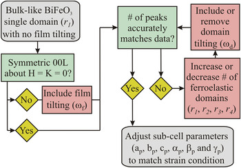
HRXRD-RSM measurements were performed using a four-circle Bruker-axs® (Madison, WI) D8 Advance diffractometer with a highly monochromatic Cu kα1 source. Data collection was performed in an asymmetric geometry,Reference Xu, Hiraka, Shirane, Li, Wang and Viehland15 where two-dimensional datasets were recorded. To analyze the scattering data, the subcell approach was utilized focusing on (i) epitaxial strain, (ii) domain arrangements, and (iii) lattice rotations through iterative transformations between a real space model and reciprocal space. The process is outlined with a flow diagram shown in Fig. 2, while the underlying algebra is provided for reference in the Appendix. The correct real space model was identified by matching the transformed Bragg peak locations with the maximum scattering intensity.
Flow diagram used to iteratively match the reciprocal space mapping results (see Appendix for details).

III. RESULTS
The results for four (001) BiFeO3 thin films heterostructures are presented (A–D). For the modeled Bragg peak locations, black squares and best matched white circles were used to represent the substrate and BiFeO3 film, respectively. The twin wall configurations, if present, are also established for each heterostructure. Additionally, subscript (p) is used to denote the strain-adjusted, pseudo-rhombohedral subcell parameters of the BiFeO3 films.
A. Monodomain BiFeO3 film on vicinal SrTiO3 substrate
Substrate miscut is known to have a large effect on the structure of BiFeO3 thin films.Reference Chu, Cruz, Yang, Martin, Yang, Zhang, Lee, Yu, Chen and Ramesh16 Therefore, to establish the utility of the x-ray method and to specifically address the structure of BiFeO3 films on vicinal surfaces, a BiFeO3 film was deposited on (001) SrTiO3 substrates miscut 4° about [1 0] using a thin SrRuO3 epitaxial interlayer (50 nm). The SrRuO3 interlayer was included to facilitate charge screening at the interface,Reference Kopal, Bahnik and Fousek17 although the SrRuO3 peaks were ignored in the analysis.
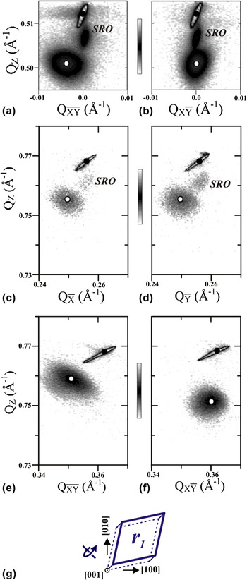
Initially, close inspection of the (002) peak indicated that the film growth direction was macroscopically tilted from the [001] SrTiO3 towards the surface normal. This was evident by the non-zero in-plane component ( ≠ 0) of the BiFeO3 002 peak in Fig. 3(a). To accurately account for this tilting, a macroscopic film rotation of ω f = 0.43° about
 = [1
 0]/√2 was included into the model. This degree of film rotation resulted in a good match between the simulated Bragg peak locations and the experimentally measured peaks observed [Figs. 3(a)–3(f)].
RSMs of BiFeO3/SrRuO3/(001) SrTiO3 miscut 4° about [1 0] with model Bragg peak locations. (a, b) The RSMs of the (002) reflection are shown with two in-plane Q. Off-axis reflections
 03, 0
 3,
 3, and
 3 are shown in RSMs (c), (d), (e), and (f), respectively. (g) A schematic of the BiFeO3 structure is shown. The curled arrow represents the direction of lattice rotation (ω f).

The number of structural BiFeO3 domains was found by counting the number of observed Bragg peaks near the (002), ( 03), (0
 3), (
 3) and (1
 3) RSMs [Figs. 3(a)–3(f)]. Each map exhibited a single film peak, establishing that a single structural domain (denoted as r 1) was enough to match the data accurately.
After the determination of the film rotation from miscut and domain structure, lattice strains were addressed. For this BiFeO3 film, the average c p expanded 0.72% with respect to bulk (3.964 Å), consistent with the compressive in-plane lattice mismatch with the SrTiO3 substrate (3.905 Å). The in-plane lattice parameters of BiFeO3 (a p and b p) were extracted from RSM data near ( 03) and (0
 3) [Figs. 3(c) and 3(d)]. The in-plane parameters a p = b p = 3.945 Å were found to exist between the SrTiO3 substrate and bulk BiFeO3 lattice parameters indicating the initial biaxial misfit strain (−1.4%) was partially relaxed. Shear distortions of the BiFeO3 subcell were also isolated. Unlike the lattice parameters that exhibited strain, the subcell angles α p, β p, and γ p matched well with the bulk value (αr = 89.43°) with no detectable shear distortions.
The epitaxial arrangement on the vicinal SrTiO3 substrate is shown schematically in Fig. 3(g). The single structural domain was labeled r 1 with the curled arrow indicating the direction of the macroscopic film rotation, ω f. Since only a single structural variant was found to exist in this film, no twin walls are expected.
B. Multidomain BiFeO3 film on exact SrTiO3 substrate
The HRXRD-RSM method was also applied to a (001) BiFeO3 film on an exact (001) SrTiO3 substrate, which generated a more complex domain structure. Similar BiFeO3 heterostructures have been reported on previously, however, without full agreement pertaining to the film structure.Reference Xu, Hiraka, Shirane, Li, Wang and Viehland15, Reference Daumont, Farokhipoor, Ferri, Wojdel, Iniguez, Kooi and Noheda18–Reference Saito, Ulyanenkov, Grossmann, Ress, Bruegemann, Ohta, Kurosawa, Ueki and Funakubo20
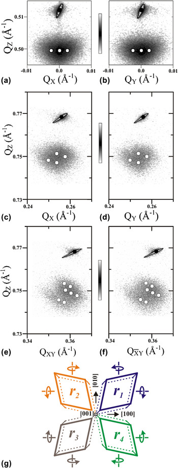
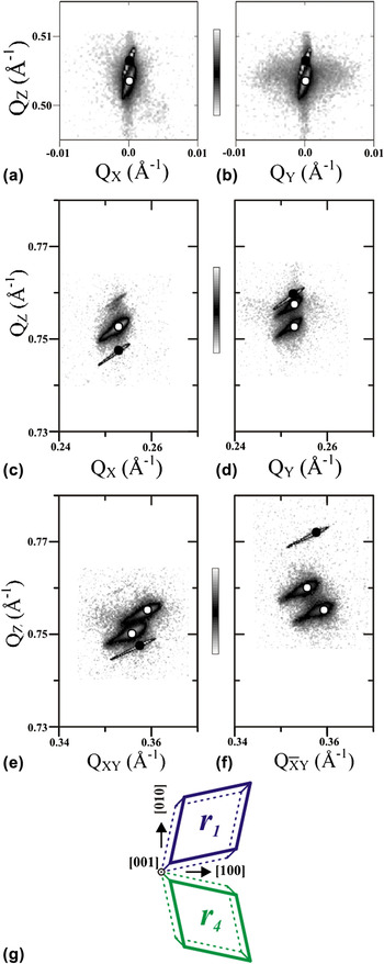
The RSM data for the BiFeO3 film is shown in Fig. 4. For the BiFeO3 film, macroscopic film rotation (ω f) was absent. This was supported in the RSM data where the (002) reflection about QX = 0 and QY = 0 is highly symmetric as shown in Figs. 4(a) and 4(b), respectively.
RSMs of BiFeO3/(001) nonmiscut SrTiO3 with modeled Bragg peak locations. (a, b) The RSMs of the (002) reflection are shown with two in-plane Q. Off-axis reflections 103, 013, 113, and  13 are shown in RSMs (c), (d), (e), and (f) respectively. (g) A schematic of the resulting real space BiFeO3 structure shows the direction of lattice rotations (ω d) with curved arrows. The total number of structural variant for this film was 12.

Establishing the number of ferroelastic variants was more difficult because of the high degree of peak overlap observed for the BiFeO3 reflections in each scattering zone [Figs. 4(a)–4(f)]. To resolve the number of ferroelastic domains, it was beneficial to consider the maximum number of expected structural variants on a cubic surface plane. Simply stretching along each of the four diagonals results in four ferroelastic domains, but with domain tilting (ω d), this number increases. These local lattice tilts are caused by the preference for coherent vertical twin walls resulting in small rotations (±ω d) about the [100] and [010] axes. Considering this possibility, the maximum number of structural variants may be estimated, where [4(flat ferroelastic domains) + [4(ferroelastic domains) · 4(rotations)]] = 20 structural variants. However, modeling the diffraction pattern with these 20 structural variants did not accurately match the RSM data with poor fits to the {103} and {113} scattering data (not shown). Instead, a much closer match was obtained by limiting the number of domain rotations (ω d), to a single sense about the [100] and [010] axes or [4(flat ferroelastic domains) + [4(ferroelastic domains) · 2(rotations)]] = 12 structural variants. Simulating the Bragg peaks from these 12 structural variants matched the experimental data in all scattering zones as can be seen in Figs. 4(a)–4(f). The best fit was obtained with domains having a tilt, ω d = 0.3°.
Strain was also measured, where the out-of-plane lattice parameter c p elongated 1.03%, again consistent with the compressive in-plane biaxial misfit with the SrTiO3 substrate. The in-plane lattice parameters neither matched the substrate nor the bulk BiFeO3, where a p = b p = 3.939 Å, indicating partial in-plane strain relaxation and similar to the monodomain BiFeO3 film. In contrast, the 12-structural variant film exhibited small shear distortions, where α p = β p = γ p = 89.50°. This small difference of 0.07° from bulk BiFeO3 (89.43°) is close to the resolution limit, yet detectable, and indicative that BiFeO3 film is on average slightly sheared toward cubic.
A schematic of the structural variants for the film is shown in Fig. 4(g). The four ferroelastic domains (r 1–4) are labeled and tilting is indicated with arrows about the [100] and [010] axes. In this state, vertical twin walls were present in this heterostructure and intersect to generate both (010)-type and (100)-type twin walls.
C. BiFeO3 film with nonrotated domains on TbScO3 substrate
Rare-earth orthoscandate substrates, including TbScO3, have reduced lattice mismatches with BiFeO3 increasing the critical thickness for strain relaxation.Reference Schlom, Chen, Eom, Rabe, Streiffer and Triscone21 Also, BiFeO3 films on (001) rare-earth orthoscandate substrates exhibit different mesostructures compared with those observed on SrTiO3 substrates. Specifically, BiFeO3 films on (001) TbScO3 tend to exhibit high fractions of well-ordered (101)-type twin walls and (010)-type twin walls, which can be differentiated by rocking curves that are sensitive to (00L) splitting.Reference Folkman, Baek, Jang, Eom, Nelson, Pan, Li, Chen, Kumar, Gopalan and Streiffer22, Reference Chu, He, Yang, Yu, Martin, Shafer and Ramesh23 In this subsection, a BiFeO3 film was chosen for HRXRD-RSM analysis that exhibited an absence of (00L) splitting in rocking scan signatures (not shown).
The presence of macroscopic film tilt (ω f) was checked by observing the symmetry of the BiFeO3 (002) reflection [Figs. 5(a) and 5(b)]. Here, each of the out-of-plane RSM maps exhibited a single sharp film reflection that was symmetric about QX = 0 and QY = 0; therefore, no macroscopic film tilt (ω f) was present.
RSMs of nonrotated BiFeO3/(001) TbScO3 with modeled Bragg peak locations. (a, b) The RSMs of the (002) reflection are shown with two in-plane Q. Off-axis reflections 103, 013, 113, and  13 are shown in RSMs (c), (d), (e), and (f) respectively. (g) A schematic of the resulting real space BiFeO3 structure is shown. Note, [001] ‖ [110]o and [010] ‖ [001]o.

Although a single sharp diffraction peak existed at 002 [Figs. 5(a) and 5(b)], the number of structural domains was found to be larger than one. This was evident by peak splitting in the off-axes RSMs located at (013), (113), and ( 13) [Figs. 5(d)–5(f)]. Since a maximum of two peaks were observed, two-domain combinations were tried as models until accurately matching the scattering data. A good match was made with two ferroelastic domains (r 1 and r 4) off-set in-plane by 90°. Furthermore, tilting of the individual domains was not necessary to match the RSM data (ω d = 0°). Therefore, the two ferroelastic domains were found to lie flat in the (001) growth plane.
Lattice strains were measured, where the out-of-plane lattice parameter elongated slightly to 3.972 Å consistent with the small biaxial misfit BiFeO3 has with TbScO3 (<−0.15%). The smaller lattice misfit with the substrate (<0.15%) resulted in a high level of in-plane coherency to the TbScO3 substrate as indicated by good fits with lattice matched in-plane parameters a p and b p. Shear strain was similar to the monodomain BiFeO3 film, α p, = β p = γ p = 89.43°, again indicating no detectable shear distortions from the bulk.
The arrangement of the two nontilted ferroelastic domains is depicted in Fig. 5(g) (ω f = ω d = 0°). Although more than two structural variants were found to exist, the absence of domain tilting meant that slanted (101)-type twin walls were present at the domain boundaries.
D. A BiFeO3 film with rotated domains on TbScO3 substrate
The structure of the BiFeO3 on TbScO3 heterostructure was again studied, in this case with a film exhibiting a high degree of (00L) splitting as evident from rocking scan signatures. Like the other BiFeO3 film on TbScO3, no macroscopic film rotation (ω f) was present, where the (002) reflections were symmetric about QX = 0 and QY = 0 [Figs. 6(a) and 6(b)]. Also, the maximum number of Bragg peaks in any of the RSMs measured equaled two [Figs. 6(a)–6(f)]. Therefore, two ferroelastic domains were included (r 1 and r 4).
RSMs of rotated BiFeO3/(001) TbScO3 nonmiscut with modeled Bragg peak locations. (a, b) The RSMs of the (002) reflection are shown with two in-plane Q. Off-axis reflections 103, 013, 113, and  13 are present in RSMs (c), (d), (e), and (f) respectively. (g) A schematic of the resulting real space BiFeO3 structure is shown. Curled arrows represent the direction of lattice rotations (ω d).

However, a good match was not achieved until inclusion of finite domain tilting (ω d). Specifically, the r 1 and r 4 domains were rotated +ω d and −ω d about  = [100] (Eq. 5), respectively. A value of ω d = 0.53° gave the best match between the modeled peak locations and the measured (002), (
 03), (0
 3), (
 3) and (1
 3) RSMs [Figs. 6(a)–6(f)].
After accurately matching the structural variants present and level of domain tilting (ω d), the strain state of the film was measured. No differences in the principle or shear strains were detected in comparison with the other BiFeO3 film on TbScO3 (C). Therefore, the primary structural difference between these two heterostructures was the presence of domain tilting.
The final arrangement of structural variants (r 1 and r 4) is shown in Fig. 6(g) along with domain tilting. The intersection of the r 1 and r 4 tilting domains occurs at a vertical (010)-type twin wall.
IV. DISCUSSION
Ferroelasticity is fundamental to the BiFeO3 structure. This is because BiFeO3 has spontaneous rhombohedral strain between room temperature and typical thin films growth temperatures, <800 °C (in bulk).Reference Bucci, Robertso and James24 Therefore, spontaneous strains in small BiFeO3 islands or clusters strongly interact with the single-crystal substrate surface during the initial stages of film growth.
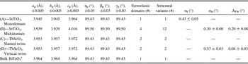
Substrate vicinality was one factor that strongly affected the ferroelastic domain structure. This is because ferroelastic domains located at step and kink sites experience anisotropic stresses during the initial stages of the growth process. To minimize the excess strain energy, preferred ferroelastic domain orientations are realized.Reference Chu, Cruz, Yang, Martin, Yang, Zhang, Lee, Yu, Chen and Ramesh16, Reference Jang, Baek, Folkman, Das, Shafer, Chen, Nelson, Pan, Ramesh and Eom25 For instance, a ferroelastic domain at a kink site defined by a (001) terrace and two intersecting step edges, (100) and (010), will preferably orient the maximum spontaneous shear strain along [111]. In this configuration, the step edges of the substrate are not competing against the spontaneous strain in the BiFeO3 layer. This correlation between substrates vicinality and ferroelasticity was supported by the fact BiFeO3 thin films on exact (001) SrTiO3 exhibited four ferroelastic domains, while in contrast using a SrTiO3 substrate with an intentional miscut (high density of kink sites) the number was reduced to single ferroelastic domain (see Table I). Closely connected to the vicinality of the substrate was film tilting (ω f). The general film tilting behavior observed was consistent with previous studies of epitaxial heterostructures exhibiting a combination of substrate vicinality and lattice misfit between substrate and film (i.e., anisotropic strain relaxation).Reference Nagai26, Reference Ayers, Ghandhi and Schowalter27
Summary of 200 nm thick (001) epitaxial BiFeO3 thin films on various substrates.

a Bulk unit cell parameters of BiFeO3 from Kubel et al.Reference Locherer, Hayward, Hirst, Chrosch, Yeadon, Abell and Salje9
Substrate symmetry was another detail that strongly influenced the ferroelastic domain structure. Here, BiFeO3 films deposited on exact cubic (001) SrTiO3 substrate exhibited all four ferroelastic domains in contrast with films on exact orthorhombic (001) TbScO3 substrate that only exhibited two (see Table I). Both substrates had low step and kink sites densities, with miscuts < 0.1°; therefore, vicinality could not explain the differences in ferroelastic structure. Instead, an interface shear mechanism was proposed based on the shape and arrangement of the BiFeO3 film subcells and substrate subcell. The two BiFeO3 ferroelastic domains on TbScO3 substrates exhibited a rhombohedral-like spontaneous shear of the subcells along [111] and [1 1], respectively. Viewed as a single domain doublet, the net spontaneous shear from these two ferroelastic domains is ([111] + [1
 1])/2 = [101]. Interestingly, this direction was coincident with the monoclinic distortion of the TbScO3 subcell, where the subcell is distorted by the angle β m (Fig. 1). Therefore, it is suggested that the three-dimensional low symmetry of the TbScO3 lattice causes anisotropic bonding (net) across the interface causing a reduction in the number of ferroelastic domains. Although the more standard explanation is limited to the anisotropy of the 2D rare-earth orthoscandate plane,Reference Folkman, Baek, Jang, Eom, Nelson, Pan, Li, Chen, Kumar, Gopalan and Streiffer22, Reference Chu, He, Yang, Yu, Martin, Shafer and Ramesh23 here it is pointed out that for TbScO3 the percent difference between β m and 90° is 1.0%, while the percent difference between a m and b m is an order lower at 0.1%.
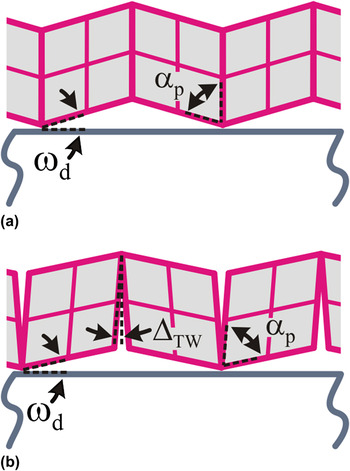
Local domain rotations (ω d) were also identified indicating vertical twins walls in the film, where neighboring ferroelastic domains rotate with an opposite sense to maintain structural coherency at their intersection.Reference Streiffer, Parker, Romanov, Lefevre, Zhao, Speck, Pompe, Foster and Bai28, Reference Romanov, Lefevre, Speck, Pompe, Streiffer and Foster29 The nature of these walls was investigated more thoroughly using the local domain rotation ω d and inter subcell angle α p to give a measure of the extrinsic twin wall distortion. Specifically, an intrinsic vertical twin wall with no distortion was defined by 90° − α p − ω d ≈ 0.0°,Reference Streiffer, Parker, Romanov, Lefevre, Zhao, Speck, Pompe, Foster and Bai28 while a wall with distortion was defined 90° − α p − ω d = ΔTW; see Figs. 7(a) and 7(b), respectively.
Schematic of twin walls in a (001) BiFeO3 thin film. A vertical twin wall is shown (a) without extrinsic angular distortion (ΔTW) and (b) with extrinsic angular distortion (ΔTW), where ΔTW = 90° − α p − ω d.

Two of the films studied in this work exhibited vertical twin walls, a BiFeO3 film on exact (001) TbScO3 with ΔTW = 0.04° ± 0.03° and a BiFeO3 film on exact (001) SrTiO3 with ΔTW = 0.20° ± 0.08° (see Table I). Note the larger peak widths of the BiFeO3 film on SrTiO3 resulted in larger uncertainties of ΔTW. In comparison, the inter subcell angles, α p, were fairly close for the two films, although a slight difference was detected (0.07° ± 0.03°). This small difference suggested that the BiFeO3 film on SrTiO3 was strained slightly towards a more cubic-like subcell; however, both films exhibited values of α p close to their bulk counterpart. A larger difference, however, was detected in the value of ω d where a highly nonideal value of 0.3° was found for the BiFeO3 film on SrTiO3 (ideal tilt, 90° − α p = ω d). Importantly, this means that the primary cause of vertical twin wall distortion was incomplete domain tilting (ω d).
Here, two possibilities for the incomplete domain tilting are proposed. One is strain relaxation, which was detected in the BiFeO3 film on SrTiO3 from the in-plane measurements of a p and b p. Strain relaxation is accompanied by the formation of misfit dislocations that can potentially annihilate preexisting coherency dislocations or pile up locally within the film; either way altering the degree at which the domain rotates across the twin wall (ω d). A second explanation is that the degree of domain tilting (ω d) varies with BiFeO3 film thicknesses. During the initial stages of growth, ferroelastic domains are epitaxially clamped to the substrate such that the tilting (ω d) is incomplete and distortion at the boundaries is a maximum (the spontaneous rhombohedral-like strain of the subcell is roughly maintained). As the film thickness and domain size increase, buckling occurs at the boundaries partially regaining the ideal domain tilt and relieving the twin wall distortion. This process maybe exacerbated in films with complex multidomain morphologies and perhaps explains some of the differences in RSM data observed for thin and thick films of (001) BiFeO3 on SrTiO3 in the literature.Reference Liu, Yang, Yao and Wang19, Reference Saito, Ulyanenkov, Grossmann, Ress, Bruegemann, Ohta, Kurosawa, Ueki and Funakubo20
Interestingly, the extrinsic twin wall distortions (ΔTW) measured may also provide insights on nonequilibrium domain wall widths, which are important variables in modeling properties and domain morphologies in ferroelectric thin films.Reference Schilling, Adams, Bowman, Gregg, Catalan and Scott10 Intrinsically, ferroelectric and ferroelastic wall widths are on the order of a lattice constant, but variations ∼20 nm are typically observed in real samples.Reference Catalan, Lukyanchuk, Schilling, Gregg and Scott30 In BiFeO3 thin films on TbScO3 substrates, sharp intrinsic-like vertical twin walls have been observed by high-resolution transmission electron microscopyReference Folkman, Baek, Jang, Eom, Nelson, Pan, Li, Chen, Kumar, Gopalan and Streiffer22 while measurements of ΔTW by HRXRD-RSM were near zero (Table I). This suggests that a correlation may exist between values of ΔTW and the twin wall width. Using the measured value of ΔTW for BiFeO3 on SrTiO3 with the film thickness t = 200 nm, the twin wall width can be approximated, t·ΔTW ≈ 40 nm. In comparison, for BiFeO3 on TbScO3, t·ΔTW ≈ 8 nm. Therefore, vertical twin walls in BiFeO3 films on SrTiO3 substrates likely have larger than equilibrium wall widths according to the HRXRD-RSM analysis. This suggests that the twin wall width is not constant and will depend strongly on the degree of incomplete tilting, ω d.
In summary, the structure of (001) BiFeO3 thin films were presented with a systematic HRXRD-RSM method, which is highly appropriate to low symmetry epitaxial heterostructures. The method was developed such as to include (i) epitaxial strain, (ii) ferroelastic domains, and (iii) lattice rotations. These important structural aspects of the BiFeO3 film laid a foundation necessary to extract the extrinsic distortion of vertical twin walls. A larger twin wall distortion, ΔTW, was detected in BiFeO3 films on exact (001) SrTiO3 substrates, in comparison to BiFeO3 films on exact (001) TbScO3. The cause of this extrinsic distortion was found to originate from incomplete domain tilting (ω d) providing a path to engineer twin wall properties in epitaxial BiFeO3 films and other low symmetry rhombohedral heterostructures.
ACKNOWLEDGMENTS
We thank Dr. Dillon Fong at Argonne National Labs for reading of the manuscript and providing constructive comments. This work is supported by the Army Research Office under Grant No. W911NF-10-1-0362.
APPENDIX
The bulk real space structures of the BiFeO3 film and the substrates were described with individual sets of basis vectors in a single Cartesian coordinate system (see subcells in Fig. 1). After defining the heterostructure in real space, the basis vectors were transformed to reciprocal space using standard Gibb’s relations.Reference Shmueli31 The real space lattice corresponding to the substrates was fixed. In contrast, the real space lattice of the BiFeO3 film was matched to the data considering the following parameters: subcell definition (a p, b p, c p, α p, β p, and γ p) and parameters associated with structural variants (R), specifically (r 1, r 2, r 3, or r 4) and lattice rotations ( , ω).
The substrate lattice (Fig. 1) transformation matrices were defined for SrTiO3 with a = 3.905 Å and TbScO3 with a m = c m =  = 3.953 Å, b m =
 = 3.957 Å, and β m =
 = 87.243°.Reference Velickov, Kahlenberg, Bertram and Uecker12, Reference Liferovich and Mitchell32, Reference Velickov, Kahlenberg, Bertram and Bernhagen33


A transformation matrix was also used to define the BiFeO3 film subcell (F) although in contrast to the substrates, the lattice parameters a p, b p, c p, and intercell angles α p, β p, and γ p were made flexible as to fit the experimental data (general triclinic structure).

where,


The expressions for F were geometrically derived assuming the subcell initially lies flat on the crystallographic growth surface (F [2,3] = F [1,3] = 0) and equally spaced from the [100] and [010] axes.
Four ferroelastic variations are in a rhombohedral system which quadruples the number of independent lattices that must be considered. These were accounted for using separate matrices, r 1–4, where each may be visualized as a stretching of the subcell along the <111> diagonals (Fig. 1).Reference Streiffer, Parker, Romanov, Lefevre, Zhao, Speck, Pompe, Foster and Bai28

Additionally, structural variants (R) were considered to account for the possibility of lattice rotations. This was accomplished considering the ferroelastic variants (r 1–4) and a rotation matrix.Reference Shmueli31

Here ω is the magnitude of the rotation about a unit vector  = [k 1, k 2, k 3]. Here discussion was limited to ω f and ω d, which are notations used in the text to describe lattice rotation of the entire film due to miscut and individual ferroelastic domains due to twin walls, respectively.
At this point, transformation of all the individual real space lattices of the film and substrate to reciprocal space (H K L) was performed using the standard Gibb's relations generating respective reciprocal lattices in the same coordinate system (Fig. 1).Reference Shmueli31
To compare with the measured 2D RSM data, the nearest scattering vector GHKL of each reciprocal lattice was projected onto the exact plane measured in reciprocal space. The projected G Proj was calculated with,

where P defines the measured plane in reciprocal space (P / is the transpose). For {002} and {103} reflections,

and for {113} reflections,

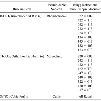
A full list of reflections used in this study is given in Table II with the position equivalent bulk Bragg reflections. The Bragg reflections for single-crystal substrates were used for calibration.
Position select equivalent Bragg reflections for bulk unit cell and sub-cell