Research carried out in astrophysics, planetary, and material sciences requires and seeks a thorough understanding of the behavior of matter at high pressures. For example, the equation of state (EOS) of iron at pressures of 1–4 Mbar is crucial in order to determine the state of the Earth's core (Belonoshko et al., Reference Belonoshko, Ahuja and Johansson2003; Boehler, Reference Boehler2000; Laio et al., Reference Laio, Bernard, Chiarotti, Scandolo and Tosatti2000). EOS data at 0.1 Mbar is required to establish the state and the composition in Earth's lower mantle (Boehler, Reference Boehler2000; Zhang & Weidner, Reference Zhang and Weidner1999), while the dynamics of the processes in the mantle is considered to be dependent on the structural phase transformation kinetics (Solomatov & Stevenson, Reference Solomatov and Stevenson1994). The pursuit after novel materials for technological applications (McMilan, Reference McMillan2002) also entails a detailed understanding of the kinetics of the high-pressure phase transitions. Modeling the physical processes during the projectile impact relevant to meteoroid protection and crater formation (O'Keefe & Ahrens, Reference O'Keefe and Ahrens1999) requires the solid-state dynamical response data at ultrahigh strain rates. The questions associated with the hydrogen EOS at high pressures are especially important for understanding the structure and evolution of the hydrogen-bearing astrophysical objects such as the giant planets like Saturn and Jupiter (Guillot, Reference Guillot1999; Sauman et al., Reference Sauman, Chabrier, Wagner and Xie2000) as well as for inertial fusion energy research including novel approaches (Azteni & Meyer-ter Vehn, Reference Azteni and Meyer-ter Vehn2004; Lindl et al., Reference Lindl, Richard, Berger, Glendinning, Glenzer, Haan, Kauffman, Landen and Suter2004; Azizi et al., Reference Azizi, Hora, Miley, Malekynia, Ghoranneviss and He2009).
There exist several methods to investigate the EOS in high pressure materials. Most prominent are shock wave experiments (McQueen et al., Reference McQueen, Fritz, Morris, Asay, Graham and Straub1983; Neal, Reference Neal1976; Collins et al., Reference Collins, Celliers, Da Silva, Cauble, Gold, Foord, Holmes, Hammel, Wallace and Ng2001; Knudson et al., Reference Knudson, Hanson, Bailey, Hall and Asay2003; Fortov et al., Reference Fortov, Ilkaev, Arinin, Burtzev, Golubev, Iosilevskiy, Khrustalev, Mikhailov, Mochalov, Ternovoi, Zhernokletov, Nardi, Maron and Hoffmann2007) but other techniques can explore different regions in phase space (see, e.g., Weir et al., Reference Weir, Lippincott, Valkenburg and Bunting1959; Jayarama, Reference Jayarama1986; Bakshi et al., Reference Bakshi, Eliezer, Henis, Nissim, Perelmutter, Moreno, Sudai and Mond2009). Quasi-isentropic compression using ramp wave loading (RWL) (Reisman et al., Reference Reisman, Toor, Cauble, Hall, Asay, Knudson and Furnish2000; Hayes, Reference Hayes2001; Cauble et al., Reference Cauble, Reisman, Asay, Hall, Knudson, Hemsing, Goforth and Tasker2002; Hayes et al., Reference Hayes, Hall, Asay and Knudson2004; Rothman et al., Reference Rothman, Davis, Maw, Robinson, Parker and Palmer2005; Davis, Reference Davis2006; Chhabildas & Barker, Reference Chhabildas and Barker1986; Barnes et al., Reference Barnes, Blewett, McQueen, Meyer and Venable1974; Lorenz et al., Reference Lorenz, Remington, Pollaine, Colvin, Braun, Lasinski, Reisman, McNaney, Greenough, Wallace, Louis and Kalantar2004, Reference Lorenz, Edwards, Glendinning, Jankowski, McNaney, Pollaine and Remington2005; Smith et al., Reference Smith, Eggert, Jankowski, Celliers, Edwards, Gupta, Asay and Collins2007; Swift & Johnson, 2005) allows sampling EOS data along an isentrope up to several Mbar pressures, located on the phase diagram between the parameter regions accessible with diamond anvil cells (Weir et al., Reference Weir, Lippincott, Valkenburg and Bunting1959; Jarayama, 1986) and shock wave experiments (McQueen et al., Reference McQueen, Fritz, Morris, Asay, Graham and Straub1983; Neal, Reference Neal1976). Unlike a shock wave experiment where a single point on a shock adiabat is obtained, in RWL experiments, a continuous set of data points is recorded and the solid state of a sample is ensured up to high pressures. The RWL method was also shown to be a more sensitive tool for studying the dynamics of the ultrafast structural phase transformations than the shock-wave based methods (Smith et al., Reference Smith, Eggert, Saculla, Jankowski, Bastea, Hicks and Collins2008; Bastea et al., Reference Bastea, Bastea, Emig, Springer and Reisman2005; Dolan et al., Reference Dolan, Knudson, Hall and Deeney2007).
RWL has been demonstrated with different drivers such as magnetic pulse loading using high-current pulsed power generators with typical loading times of 100 ns (Reisman et al., Reference Reisman, Toor, Cauble, Hall, Asay, Knudson and Furnish2000; Hayes, Reference Hayes2001; Cauble et al., Reference Cauble, Reisman, Asay, Hall, Knudson, Hemsing, Goforth and Tasker2002; Hayes et al., Reference Hayes, Hall, Asay and Knudson2004; Rothman et al., Reference Rothman, Davis, Maw, Robinson, Parker and Palmer2005; Davis, Reference Davis2006), gas guns (Chhabildas & Barker, Reference Chhabildas and Barker1986) and high explosives (Barnes et al., Reference Barnes, Blewett, McQueen, Meyer and Venable1974), with graded density impactors (1 µs) and high-power lasers (10 µs) (Lorenz et al., 2004, 2005; Swift & Johnson, Reference Swift and Johnson2005; Smith et al., Reference Smith, Eggert, Jankowski, Celliers, Edwards, Gupta, Asay and Collins2007). On the other hand, intense heavy ion beams are an excellent tool to create high energy density in matter (Hoffmann et al., Reference Hoffmann, Blazevic, Ni, Rosmej, Roth, Tahir, Tauschwitz, Udrea, Varentsov, Weyrich and Maron2005; Tahir et al., Reference Tahir, Deutsch, Fortov, Gryaznov, Hoffmann, Kulish, Lomonosov, Mintsev, Ni, Nikolaev, Piriz, Shilkin, Spiller, Shutov, Temporal, Ternovoi, Udrea and Varentsov2005). Here, we will combine the two and suggest and analyze a new scheme for planar RWL experiments using intense heavy ion beam as a driver. This scheme has the advantage to using the excellent control available for heavy ion beams: the beam diagnostics as well as the energy deposition are well studied (Becker et al., Reference Becker, Hug, Forck, Kulish, Ni, Udrea and Varentsov2006; Varentsov et al., Reference Varentsov, Spiller, Tahir, Hoffmann, Constantin, Dewald, Jacoby, Lomonossow, Neuner, Shutov, Wieser, Udrea and Bock2002; Gericke, Reference Gericke2002a, Reference Gericke2002b; Gericke et al., Reference Gericke, Schlanges and Bornath2002; Nardi et al., Reference Nardi, Maron and Hoffmann2009). Moreover, the effective temperature in the absorber can be measured as well (Ni et al., Reference Ni, Kulish, Mintsev, Nikolaev, Ternovoi, Hoffmann, Udrea, Hug, Tahir and Varentsov2008). The long absorption range and the variable focal spot size and shape of a high-energy ion beam delivered by the SIS-18 heavy ion synchrotron of the GSI Helmholtzzentrum für Schwerionenforschung in Darmstadt, allow designing RWL experiments with fairly planar geometry. The beam parameters needed to generate pressures of up to 4 Mbar in aluminum and 7 Mbar in iron are well within the reach of the uranium beams that will be delivered at the new Facility for Antiproton and Ion Research (FAIR), being built in Darmstadt as well. The uranium beam intensities needed to generate pressures approaching 1 Mbar will become available with the completion of the high-current upgrade of SIS-18 (Spiller et al., Reference Spiller, Barth, Dahl, Eickhoff, Spaedtke and Hollinger2006) in the year 2009. In RWL experiments with intense ion beams, the typical compression times from zero to the maximum pressure are about 20 ns for the aluminum and about 10 ns for the iron samples considered here, which is comparable with the dissipative relaxation times of aluminum and iron (Swegle & Grady, Reference Swegle and Grady1985; Boettger & Wallace, Reference Boettger and Wallace1997). Resent laser-driven experiments (Smith et al., Reference Smith, Eggert, Jankowski, Celliers, Edwards, Gupta, Asay and Collins2007) have demonstrated that at such short time scales there exists a stiffer response than had been expected from previous slower ramp compression experiments and from models relying on either static or shock-wave experiments.
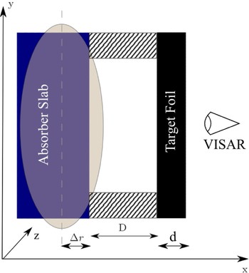
The layout of the experiment is shown in Figure 1. The ion beam with an elliptical focal spot and the Gaussian transverse intensity distribution heats an absorber slab along its surface. Lead is chosen as the absorber material. Since the stopping ranges of energetic 238U ions in lead considered here are much larger than the length of the absorber slab, the latter is heated uniformly along z axis. The focal spot size and its aspect ratio can be varied, what allows for generating a quasi-planar ramp wave. In the manner similar to the laser-driven ramp compression or shock wave experiments (Smith et al., Reference Smith, Eggert, Jankowski, Celliers, Edwards, Gupta, Asay and Collins2007), a stepped target with rather wide steps along the z direction can be used. The presented design has also an important advantage that the target is not being preheated by energetic secondary particles and projectile fragments produced during the interaction of the beam with the absorber material.
(Color online) Schematic of the experimental design. The ion beam with an elliptic focal spot propagates in z direction. It heats the absorber slab along its surface. The depth of the beam inside the absorber slab, i.e., the distance between the beam's origin and the inner surface of the slab is Δr. The target foil of the thickness d is placed parallel to the absorber at a distance D. Hatched area represents the support washer used to coax the expanding absorber material. The velocity of the target's rear surface is recorded using a line-imaging VISAR.

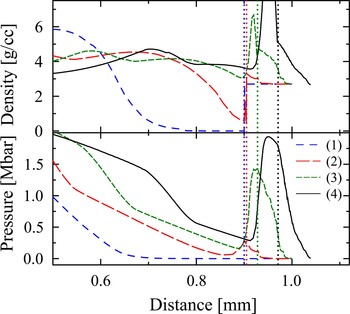
Similarly to the laser-driven RWL experiments (Lorenz et al., Reference Lorenz, Remington, Pollaine, Colvin, Braun, Lasinski, Reisman, McNaney, Greenough, Wallace, Louis and Kalantar2004), the process of the ion beam driven RWL consists of three distinct phases. First, the ion beam evaporates the absorber material of its surface or unloads the material due to a shock wave generated inside the absorber, depending on the beam intensity, focal spot size, and the distance Δr between the beam's axis and the absorber surface. At the next stage, the absorber's plasma expands into the vacuum gap. The adjustable displacement of the beam axis relative to the absorber surface allows some degree of control over the plasma expansion regime. In the last stage, the absorber's plasma piles up against the target foil thus producing a smoothly increasing pressure load in the sample. The evolution of the compression wave launched into the sample is shown in Figure 2. One can see that the compression wave gradually steepens with the distance traveled before it breaks into a shock wave. This distance determines the maximum allowed thickness of the target foil.
(Color online) Evolution of pressure and density for case (b) of Table 1. The dotted vertical lines indicate the location of the target front surface at different times. The phases of the process are: (1) t = 59 ns—the evaporated absorber material is accumulating at the front surface of the aluminum sample; (2) t = 78 ns—the compression has set off; (3) t = 86 ns—the accumulation continues; compression wave reaches the rear surface of the sample before the shock wave has formed; (4) t = 94 ns—the motion of the rear surface of the target foil can be detected.

Provided the compression wave launched into the sample does not break into a shock wave, the pressure and density history at the front surface of the sample can be reconstructed using the bootstrap back integration method (Hayes, Reference Hayes2001). The method uses the rear surface velocity history as an initial condition for a Riemann solver.
The major benefit of the presented experimental design as compared to other approaches for EOS measurement with heavy ion beams (Arnold et al., Reference Arnold, Colton, Fenster, Foss, Magelssen and Moretti1982; Hoffmann et al., Reference Hoffmann, Fortov, Lomonosov, Mintsev and Tahir2002) is two-fold. First, the EOS along a compression adiabat can be determined by measuring of only one parameter—the rear surface velocity employing a line-imaging VISAR as the principal diagnostics. Second, this design does not rely on detailed knowledge of the beam-matter interaction processes such as, e.g., stopping power, since the beam energy is not deposited into the sample directly (Grinenko et al., Reference Grinenko, Gericke, Glenzer and Vorberger2008) but is converted to the kinetic energy of the absorber material. In order to interpret and use the results of the experiment, one therefore does not have to precisely measure the transverse distribution of the beam intensity at the focal plane, which can be problematic for intense focused heavy ion beams (Varentsov et al., Reference Varentsov, Fertman, Turtikov, Ulrich, Wieser, Fortov, Golubev, Hoffmann, Hug, Kulish, Mintsev, Ni, Nikolaev, Sharkov, Shilkin and Ternovoi2008). Furthermore, the presented approach requires neither high accuracy of the beam-target alignment, nor good shot-to-shot reproducibility and control of the beam parameters, such as intensity and focal spot size. Some problems related with the laser drivers such as the preheating of the target by the X-rays is naturally eliminated in this setup.
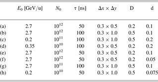
Parameters of the beam and the target geometries considered in this work is summarized in Table 1. Cases (a), (e) and (b), (f) in the table correspond to the beam parameters of the SIS-100 synchrotron to be available at FAIR (Gutbrod, Reference Gutbrod2006), cases (c), (g) correspond to the beams that will be available after completion of the SIS-18 upgrade (Spiller et al., Reference Spiller, Barth, Dahl, Eickhoff, Spaedtke and Hollinger2006), and cases (d), (h) correspond to the present SIS-18 beam available for HED physics experiments (Varentsov et al., Reference Varentsov, Fertman, Turtikov, Ulrich, Wieser, Fortov, Golubev, Hoffmann, Hug, Kulish, Mintsev, Ni, Nikolaev, Sharkov, Shilkin and Ternovoi2008, Reference Varentsov, Ternovoi, Kulish, Fernengel, Fertmand, Hugc, Menzel, Ni, Nikolaev, Shilkin, Turtikov, Udrea, Fortov, Golubev, Gryaznov, Hoffmann, Kimb, Lomonosov, Mintsev, Sharkov, Shutov, Spiller, Tahir and Wahl2006). A lead absorber slab of 400 µm thickness was considered for all the analyzed cases. The geometric parameters of the target have been adjusted to guarantee the planarity of the ramp compression wave propagating in the x direction for at least y ≤±50 µm, and to ensure a shockless compression of the target. The planarity of the designed experiment justifies a one-dimensional (1D) analysis using the 1D hydrodynamic simulation code described elsewhere (Grinenko, Reference Grinenko2009).
Parameters of the experiments with Al [cases (a)–(d)] and Fe [cases (e)–(h)] targets (see Fig. 1). E 0 is the uranium ion energy, N 0 is the number of ions per pulse, τ is the pulse duration, and Δx × Δy are the FWHM dimensions of the beam focal spot. The depth of the beam in the absorber is Δr = 0.2 mm in all the cases. All spatial dimensions listed are in millimeters

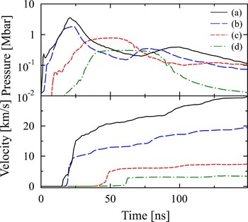
The calculated histories of the pressure at the front and the velocity at the rear surfaces of the aluminum samples are shown in Figure 3. The planarity of the compression wave can be adjusted by varying the ion beam extension in the y direction. However, this also affects the level of specific energy density deposited by the beam in the absorber. Two possible beam cross sections are compared: in case (a), the full width at half maximum height of the beam spot is 0.5 mm, whereas in case (b), 1 mm. Increasing the height of the beam spot allows one to increase the vacuum gap, which enhances the smoothness of the loading without loosing in the planarity. The curves corresponding to these two cases indicate that the enhancement of the smoothness of the loading compromises the amplitude of the compression: the maximum pressure corresponding to case (a) is about 3.5 Mbar, whereas in case (b) it is only about 2 Mbar. The maximum pressure that one can obtain using upgraded SIS-18 beam (c) is about 1 Mbar and the currently available SIS-18 beam (d) can quasi-isentropically load aluminum up to 500 kbar.
(Color online) Rear surface velocity and front surface pressure histories for different cases described in Table 1.

The strain rate (Smith et al., Reference Smith, Eggert, Jankowski, Celliers, Edwards, Gupta, Asay and Collins2007) is approximately 8 × 10⁷s−1 at the peak pressure of about 2 Mbar in the examined case (b) (see Table 1). The corresponding time to the maximum compression is approximately 20 ns, which is comparable to the low-stress steady shock rise time (Swegle & Grady, Reference Swegle and Grady1985). The laser RWL experiments by Smith et al. (Reference Smith, Eggert, Jankowski, Celliers, Edwards, Gupta, Asay and Collins2007) at similar compression times and strain rates have demonstrated a stiffening of the stress-strain response. The adjustable ion pulse duration, focal spot size, and the depth of the ion beam in the absorber allow a degree of control over the compression time, amplitude and, strain rate. This provides a unique tool to carry out parametric studies of the stress-strain response.
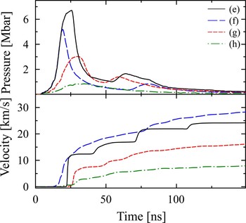
Similar analysis has been carried out for the iron samples (Table 1). The corresponding histories of the front face pressure and rear face velocity are shown in Figure 4. One can see that a Mbar pressure loading is within the reach of the existing SIS-18 beam, whereas the upgrade of the machine will provide in the nearest future the compression data of up to about 3 Mbar. Up to 6 Mbar pressures will be generated in the corresponding experiments at FAIR with the strain rates of 108 s−1.
(Color online) Rear surface velocity and front surface pressure histories for different cases of Fe samples described in Table 1.

Curves (e) and (f) in Figure 4 demonstrate the differences between the velocity traces in case of shock and adiabatic compression, respectively. In order to ensure shockless loading, the sample's thickness had to be reduced from 100 µm as in case (e) to 50 µm as in case (f). Obviously, by reducing the sample's thickness, the motion of the sample's rear surface starts earlier. This motion acts to release the pressure of the absorber's material piling up at the front surface of the sample and to reduce the pressure amplitude in the target. Therefore, a trade-off should be made to ensure the adiabatic character of the compression on one side, and to obtain the highest possible pressure on the other.
The capabilities of the high-energy heavy ion beam accelerators available at GSI and later at FAIR to drive planar RWL of solids were analyzed. It was shown that the time scales of the loading are comparable with the fastest laser drives (Lorenz et al., Reference Lorenz, Remington, Pollaine, Colvin, Braun, Lasinski, Reisman, McNaney, Greenough, Wallace, Louis and Kalantar2004; Smith et al., Reference Smith, Eggert, Jankowski, Celliers, Edwards, Gupta, Asay and Collins2007), and the amplitudes of pressure surpass those obtained using the high-power magnetic drives (Davis, Reference Davis2006). These features allow to investigate the dynamical response of solids in the regime of previously unattainable parameters and possibly the dynamics of the pressure-induced structural phase transformations (Smith et al., Reference Smith, Eggert, Saculla, Jankowski, Bastea, Hicks and Collins2008; Bastea et al., Reference Bastea, Bastea, Emig, Springer and Reisman2005; Dolan et al., Reference Dolan, Knudson, Hall and Deeney2007). Moreover, using the currently existing SIS-18 ring, ramp loading with pressures higher than 0.1 Mbar can be obtained in multi-layer targets (Dolan et al., Reference Dolan, Knudson, Hall and Deeney2007) for the purpose of studying the pressure induced phase transformations in water.
ACKNOWLEDGEMENT
Support from the Engineering and Physical Sciences Research Council of the United Kingdom and GSI-INTAS grant No.06-1000012-8707 is gratefully acknowledged.