NOMENCLATURE
- APFM
-
Artificial Potential Field Method
- BCHS
-
Boundary-Constraint Handling Scheme
- NFZ
-
No-Fly Zone
- OAS
-
Orientation Adjustment Scheme
- OBPCG
-
Composite Guidance Consisting of OAS, BCHS and PN
- PN
-
Proportional Navigation
- ac
-
the acceleration command of the missile (m/s2)
- g
-
gravitational acceleration (m/s2)
- Fa
-
the magnitude of the attractive force (N)
- Frk
-
the magnitude of the repulsive force of the k th NFZ (N)
- H
-
the distance from the missile to the boundary of the NFZ (m)
- J
-
performance index
- ka
-
the weight coefficient of the attractive force generated by the missile
- krk
-
the weight coefficient of the repulsive force generated by the k th NFZ
- n max
-
maximum maneuvering load of the missile
- N'
-
the effective navigation ratio
- p EM
-
the vector perpendicular to
 $\overrightarrow {EM} $
- p VM
-
the unit vector perpendicular to the missile velocity
- r'
-
the minimum turning radius of the missile (m)
-
${R_{\textit{TM}}}$
-
the distance from the missile to the target (m)
-
${R_{\textit{MP}}}$
-
the distance from the missile to the predicted collision point (m)
- s k + 1
-
the state at stage k+1
- tT , tM ,
-
the flight time for the target and missile to arrive at the collision point, respectively (s)
- Vc
-
missile-target closing velocity (m/s)
- VM
-
missile velocity (m/s)
- Δt
-
time difference (s)
- ε
-
small constant
- σ
-
the angle between the missile velocity and p EM
- ξ, ω n
-
damping ratio and natural frequency, respectively
-
$\dot{\lambda }$
-
the time derivative of the line-of-sight angle (rad/s)


1.0 INTRODUCTION
With the rapid development of air defense systems(Reference Tang1,Reference Wu, Luo, Chen and Liu2) , striking a target in enemy rear becomes more dangerous, because the missile is likely to be intercepted by these powerful systems. Moreover, for a time-critical target that has a narrow window to be intercepted, generating commands rapidly is crucial for the missile to re-plan a new trajectory avoiding these threaten zones, commonly called No-Fly Zones (NFZs), according to the updated information on the target states(Reference Hewitt3,Reference Gu, Yan and Xu4) . Therefore, an advanced guidance law capable of planning reference trajectory rapidly is needed(Reference Zardashti and Bagherian5,Reference Zardashti, Nikkhah and Yazdanpanah6) , as shown in Fig. 1.
Striking with multiple NFZ constraints.

During the last decades, many works have been carried out on the design of guidance laws with NFZ constraints, which can be classified into two types: offline path planning methods(Reference Xu, Duan and Liu7–Reference Yang and Zhao17) and online guidance laws(Reference Jorris and Cobb18–Reference Ruiter and de Owlia24).
Some off-line path planning methods are based on a series of waypoints and then employ path search algorithms to find a feasible trajectory by connecting proper waypoints, such as A* search algorithm, artificial bee colony algorithm(Reference Xu, Duan and Liu7), bat algorithm(Reference Wang, Chu and Mirjalili8), heuristic algorithm(Reference Bagherian and Alos9), core paths graph algorithm (Reference Mattei and Blasi10), Newton iteration scheme(Reference Yu, Liu, Liu, Tang and Zheng11) or dynamic programming(Reference Shen, Liu, Tang and Zhu12). There are still some methods using the optimal control theories to obtain the optimal reference trajectory(Reference Menon, Kim and Cheng13–Reference Mao, Zhang and Wang15). The cell decomposition methods(Reference Jun and Andrea16,Reference Yang and Zhao17) can also be applied in the off-line path planning. The offline path planning methods are good at dealing with the cases with a fixed target. However, because the methods take a long time to plan a reference trajectory, they are unable to intercept time-critical target. Especially in the case of multiple NFZs, the dynamic programming method is further challenged by the problem of the curse of dimensionality.
The online guidance laws can autonomously generate commands in real time to avoid the NFZs. Jorris and Cobb(Reference Jorris and Cobb18) obtained a closed-form guidance law by solving the optimal guidance problem where the NFZs are treated as penalty terms. But because increasing the number of the NFZs would significantly increase the guidance complexity, the guidance laws can only consider a few NFZs. There are also guidance laws based on the artificial potential field methods(Reference Shi, Cai and He19–Reference Jing, Kenneth, Rajni and Terry21). They can be classified into two kinds. In one kind, the target is assumed to generate an attractive force on the missile whereas the NFZs are assumed to exert repulsive forces(Reference Hwang and Ahuja22,Reference Peng, Sun, Dong and Li23) . In the other kind, the NFZs are assumed to generate a potential velocity vector field such that the missile can avoid the NFZs by following a trajectory identical to that of a fluid particle in the same flow field(Reference Ruiter and de Owlia24). In the presence of multiple NFZs, the Artificial Potential Field Methods (APFM) are likely to obtain a curved trajectory due to the difficulty of balancing the coefficients of different forces.
In this paper, we design a new composite guidance with multiple NFZ constraints. There are two major steps in the development of the guidance law. First, a guidance law considering only one single NFZ constraint is developed which consists of three parts: Orientation Adjustment Scheme (OAS), Boundary-Constraint Handling Scheme (BCHS)(Reference Yu and Chen25), and Proportional Navigation (PN). By predicting the collision point, OAS determines the major flight direction. BCHS controls the missile to bypass the NFZ along its boundary if necessary. When the missile gets close enough to the target, PN is used to guide the missile against the target. Next, the guidance law is extended to consider multiple NFZ constraints using multi-step decision process. The numerical simulations are conducted to verify the performance of the composite guidance. Compared with the Artificial Potential Field Method (APFM), the new guidance commands the missile to fly along a short and smooth trajectory, which leads to a small demand on maneuvering loads and achieves a high accuracy.
2.0 DESIGN OF GUIDANCE LAW WITH SINGLE NFZ CONSTRAINT
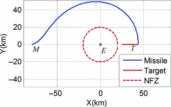
In Reference Yu and ChenRef. 25, a composite guidance law is designed to consider single NFZ constraint and consists of two parts: Virtual-Target Guidance (VTG) and BCHS. In VTG, the space is distorted such that the boundary of circle NFZ becomes a straight line, and then PN is used to steer the missile to the target in the virtual space. The method has a good performance when the missile and target are close to the boundary of the NFZ. However, if both the missile and target are far away from the NFZ, the missile would travel a long path, as shown in Fig. 2. Hence, in this paper, we improve the guidance law such that the missile is steered to the target along a trajectory as short as possible.
Trajectory for Yu guidance law.

2.1 Prediction of missile-target collision point
To achieve a short and smooth trajectory, it is better to steer the missile to the predicted collision point. As shown in Fig. 3, if the missile is commanded to always head toward the target, it is likely to bypass the NFZ along path 2 that is long and curved. If the missile is guided to the predicted collision point, it would intercept the target along the path 1, which is much shorter and smoother than path 2. In this article, we use the following iterative procedure to predict the collision point.
-
1) Detect the current states of the target and then predict its future trajectory by assuming that the target maintains its current flight condition.
-
2) Define tT as the flight time for the target required to arrive at the predicted collision point and tM as that for the missile. By ignoring the maneuvers, tT can be initially predicted by
(1)
$$\begin{equation}{t_T} = - {R_{TM}}/{\dot{R}_{TM}},\end{equation}$$

where RTM
is the distance from the missile to the target and
 ${\dot{R}_{TM}}$
is the time derivative of RTM
.
-
3) Regard the position of the target after tT as the predicted collision point.
-
4) Calculate tM by
(2)
$$\begin{equation}{t_M} = {R_{MP}}/{V_M},\end{equation}$$

where RMP is the distance from the missile to the predicted collision point and VM is the speed of the missile.
-
5) Calculate the time difference as
(3)
$$\begin{equation}\Delta t = \left| {{t_T} - {t_M}} \right|\end{equation}$$
-
6) If Δt ⩽ ε, the iteration ends; otherwise, modulate tT by Golden Section Search method as follows.
(4)
$$\begin{equation}{t_T} = \left\{ {\begin{array}{@{}*{2}{l}@{}} {{t_T} + 0.618\Delta t,}&\quad {{t_T} \le {t_M}}\\ {{t_T} - 0.382\Delta t,}&\quad {{t_T} > {t_M}} \end{array}} \right.\end{equation}$$
-
7) Repeat the above process from step 3.


The trajectories for the two cases where the missiles are commanded to head to the predicted collision point and target respectively.

2.2 Boundary constraint handling scheme
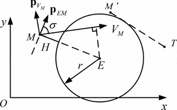
In Fig. 4, E represents the center of the NFZ. Define p
EM
as the vector perpendicular to
 $\overrightarrow {EM} $
. p
EM
can be calculated by
 $$\begin{equation}
{{{\bf p}}_{EM}} = \frac{1}{{\left\| {\overrightarrow {EM} } \right\|}}\left[ {\begin{array}{@{}*{1}{c}@{}} {{{\overrightarrow {EM} }_y}}\\ { - {{\overrightarrow {EM} }_x}} \end{array}} \right],
\end{equation}$$
where
 $\overrightarrow {EM} $
is the vector from E to M, and
 ${\overrightarrow {EM} _x}$
and
 ${\overrightarrow {EM} _y}$
represent the x- and y- components of
 $\overrightarrow {EM} $
, respectively.
BCHS guidance.

H is the distance from the missile to the boundary of the NFZ and σ ∈ [ − π, π) is the angle measured clockwise from V M to p EM . The acceleration command a c is perpendicular toV M . The equations of motion for the missile in the horizontal plane are
 $$\begin{equation}
\begin{array}{@{}l@{}} \dot{H} = {V_M}\,{\rm{sin}}\sigma \\ \dot{\sigma } = \displaystyle\frac{{{a_c}}}{{{V_M}}} + \frac{{{V_M}\,{\rm{cos}}\sigma }}{{r + H}}, \end{array}
\end{equation}$$
where r is the radius of the NFZ and VM presents the norm of V M . ac presents the norm of a c and is designed by imitating the damped harmonic oscillator as
 $$\begin{equation}
{a_c} = - \frac{{V_M^2\,{\rm{cos}}\sigma }}{{r + H}} - 2\xi {\omega _n}{V_M}\,{\rm{sin}}\sigma - \omega _n^2H\,{\rm{cos}}\sigma ,
\end{equation}$$
where ξ is damping ratio and ω n is natural frequency. Their values can be determined according to the rules presented in Reference Yu and ChenRef. 25.
To determine the direction of a c , define p VM as the unit vector perpendicular to V M
 $$\begin{equation}
{{{\bf p}}_{{V_M}}} = \frac{1}{{\left\| {{{{\bf V}}_M}} \right\|}}\left[ {\begin{array}{@{}*{1}{c}@{}} { - V_M^y}\\ {V_M^x} \end{array}} \right],
\end{equation}$$
where Vx M and Vy M represent the x- and y- components of V M , respectively.
The direction of a c can be obtained by
 $$\begin{equation}
{{{\bf i}}_{ac}} = \left\{ {\begin{array}{@{}*{2}{l}@{}} {{{{\bf p}}_{{V_M}}}}&\quad {{{{\bf p}}_{{V_M}}} \cdot \overrightarrow {EM} > 0}\\
{ - {{{\bf p}}_{{V_M}}}}&\quad{{{{\bf p}}_{{V_M}}} \cdot \overrightarrow {EM} < 0}\\
{{{{\bf p}}_{{V_M}}}}&\quad {{{{\bf p}}_{{V_M}}} \cdot \overrightarrow {EM} = 0\quad \&\quad {{{\bf V}}_M} \cdot {{{\bf p}}_{{V_M}}} \ge 0}\\
{ - {{{\bf p}}_{{V_M}}}} &\quad {{{{\bf p}}_{{V_M}}} \cdot \overrightarrow {EM} = 0\quad \&\quad {{{\bf V}}_M} \cdot {{{\bf p}}_{{V_M}}} < 0} \end{array}} \right.
\end{equation}$$
Then we can get the acceleration of BCHS as follows
 $$\begin{equation}
{{{\bf a}}_c} = {a_c} \cdot {{{\bf i}}_{ac}}
\end{equation}$$
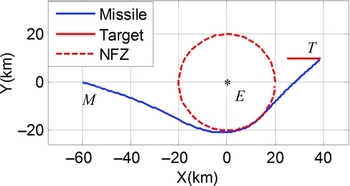
The combination of the above two schemes has already been able to handle most of the single NFZ avoidance problems. The guidance logic is like this: first, a collision point of the missile and target is predicted by the previously mentioned method and then the missile is steered to the predicted collision point. If the trajectory has the possibility of entering into the NFZ, BCHS is activated to control the missile to bypass the NFZ. When the virtual target comes into the field of view, PN is activated to guide the missile against it. An example is shown in Fig. 5.
The trajectory for the composite guidance law consisting of BCHS and PN.

2.3 Orientation adjustment scheme
In some cases, BCHS cannot obtain a short trajectory. For instance, as shown in Fig. 6, if the missile is only governed by BCHS, it would be steered to the target along the longer path 2. However, we desire that the missile bypasses the NFZ along path 1. Therefore, we introduce OAS to assist BCHS achieve the short path.
Comparison of the trajectories of the guidance laws with and without OAS.

OAS commands the missile to turn at the maximum maneuvering load n max, as follows:
 $$\begin{equation}
{{{\bf a}}_c} = {n_{{\rm{max}}}}g{{{\bf p}}_{{V_M}}},
\end{equation}$$
where g is the gravitational acceleration.
Now we introduce a general criterion for enabling OAS. As shown in Fig. 6, the line passing through the points M and E divides the plane into two parts. If V
M
and
 $\overrightarrow {MP} $
are located in different parts, OAS is activated to force the missile to bypass the NFZ from the upper side. In other words, OAS is activated if Equation (12) is satisfied.
 $$\begin{equation}
\left( {{{{\bf V}}_M},{{{\bf p}}_{EM}}} \right) \cdot \left( {\overrightarrow {MP} ,{{{\bf p}}_{EM}}} \right) < 0,
\end{equation}$$
where
 $\overrightarrow {MP} $
is the vector from the missile to the predicted collision point.
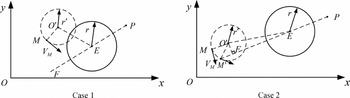
As shown in Fig. 7, we need to consider the influence of the minimum turning radius limitation on OAS, where O' is the center of the turning circle, r' is the minimum turning radius of the missile and can be obtained by Equation (13), O'F represents the distance from O' to EP, and O'E represents the distance from O' to E.
 $$\begin{equation}
r' = \frac{{V_M^2}}{{\left\| {{{{\bf a}}_c}} \right\|}}
\end{equation}$$
The cases for deactivating OAS.

In case 1 shown in the left of Fig. 7, if the missile is too close to the NFZ, i.e., r' + r > O'E, the missile will be steered into the NFZ by OAS because the available maneuvering load is limited. In case 2 shown in the right of Fig. 7, if the missile is too close to the line passing through the points P and E, OAS will be disabled at the point M' because Equation (12) becomes violated. A judgement condition of case 2 is r' > O'F. All in all, if Equation (14) is satisfied, OAS is disabled and thus BCHS is directly used to guide the missile.
 $$\begin{equation}
\left\{ {\begin{array}{@{}*{1}{l}@{}} {r' > O'F}\\ {r' + r > O'E} \end{array}} \right.
\end{equation}$$
2.4 Proportional navigation
If the segment between the missile and the predicted collision point no longer intersects with the NFZs, PN is enabled to steer the missile as
 $$\begin{equation}
{{{\bf a}}_c} = N'{V_c}\dot{\lambda }{{{\bf p}}_{{V_M}}},
\end{equation}$$
where N' is the effective navigation ratio (usually in the range of 3–5), Vc
is the missile-target closing velocity and
 $\dot{\lambda }$
is the time derivative of the line-of-sight angle.
2.5 Example for the new guidance law with single NFZ
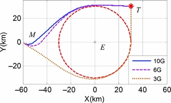
Some simulations are conducted to show the performance of the composite guidance consisting of OAS, BCHS, and PN, denoted as OBPCG, where different levels of the allowable manoeuvering loads are considered. A fixed target is considered whose location is XT = (30, 30) km. The initial conditions of the missile are
 ${{\bf XM}} = ( { - 60,0} ){\rm{km}},\;{{{\bf V}}_M} = ( {400\sqrt 2 } , { - 400\sqrt 2 } ){\rm{m}}/{\rm{s}}$
. The radius of the NFZ is rE
= 30 km. As can be seen from Fig. 8, if the maximum manoeuvering load is large enough, OBPCG can guide the missile along the short path to the target. However, if the maximum manoeuvering load is too small, the turning radius is greater than the distance from the missile to the boundary of the NFZ, and thus OBPCG has to steer the missile along the long path to the target.
The trajectories for OBPCG with different n max.

3.0 DESIGN OF GUIDANCE LAW WITH MULTIPLE NFZ CONSTRAINTS
In this section, we extend OBPCG to a guidance law capable of dealing with multiple NFZ constraints by multi-step decision process. To facilitate the design of the new guidance, a multi-step model is defined as follows(Reference Sniedovich26):
Definition 1: A multi-step decision process model is a collection (S, D, T, J) where
-
Define
$\mathbb{H}: = \{ {0,1,2, \ldots ,\Gamma } \}$
, where Γ represents the total number of steps.

-
1) S is a non-empty set containing all accessible states and defined as the state space. Denote the accessible state as s ∈ S and S(k) as the set of accessible states at stage k
$(k \in \mathbb{H})$
. -
2) D is a function which assigns a subset of set
$\mathbb{D}$
to each pair
$( {k,s} ) \in \mathbb{H} \times S$
where the set
$\mathbb{D}$
represents the decision space. Thus, D(k, s) is a set that contains all feasible decisions for state s at stage k. -
3) T is the transition function on
$\mathbb{H} \times S \times \mathbb{D}$
from the state s at stage k to the state s' at stage k + 1 by making decision x, where
$k \in \mathbb{H},s \in S,x \in D( {k,s} )$
. -
4) J is an objective function on
$S \times {\mathbb{D}^k}$
. The value of J(s
0; x
0, x
1, . . .x
Γ − 1) is calculated under the decisions x
0, x
1, . . ., x
Γ − 1 made at stages 0, 1, 2, . . ., Γ − 1, respectively, given that the initial state is s
0 ∈ S.


First, we search the NFZs intersecting with the segment between the missile and predicted collision point P. These NFZs are reordered according to the distance from the missile and marked as
 $$\begin{equation}
\begin{array}{@{}l@{}} C = \left\{ {{C_1},{C_2}, \cdots ,{C_k} \cdots ,{C_\Gamma }} \right\}\\ E = \left\{ {{E_1},{E_2}, \cdots ,{E_k} \cdots ,{E_\Gamma }} \right\}\\ rE = \left\{ {r{E_1},r{E_2}, \cdots ,r{E_k}, \cdots ,r{E_\Gamma }} \right\}, \end{array}
\end{equation}$$
where Ck represents the kth NFZ, and rEk is the radius of the kth NFZ centered at Ek .
In order to deal with the multiple NFZ constraints, a series of waypoints is set up and the multi-step decision process model is established where the position of the missile and these waypoints are used as the decision variables.
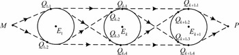
For Ck and C k + 1(1 ⩽ k < Γ), there are generally four distinct lines tangent to both. Denote the tangent points on C k + 1 by Q k + 1, i (i = 1, 2, 3, 4), as shown in Fig. 9. Note that at stage 2, there are only two tangent points on C 1. Thus, the set of the accessible states at stage k is
 $$\begin{equation}
S\left( k \right) = \left\{ {\begin{array}{@{}*{2}{l}@{}} {\left\{ M \right\},}&\quad {k = 0}\\ {\left\{ {{Q_{1,1}},{Q_{1,2}}} \right\},}&\quad {k = 1}\\ {\left\{ {{Q_{k,1}},{Q_{k,2}},{Q_{k,3}},{Q_{k,4}}} \right\},}&\quad {k = 2,3, \ldots ,\Gamma }\\ {\left\{ P \right\},}&\quad {k = \Gamma + 1} \end{array}} \right.
\end{equation}$$
The accessible states at stage k.

For this multi-step decision process, excepting the initial and terminal steps, there are four feasible decisions for making the missile bypass the NFZs at each step, as shown in Fig. 9. We define the set of all the feasible decisions as decision space
 $\mathbb{D}$
.
The performance index for minimising the trajectory length is
 $$\begin{equation}
J = {\rm{min}}\sum\limits_{k = 0}^\Gamma {\omega \left( {k,{x_k}} \right)} ,
\end{equation}$$
where ω(k, xk
) represents the path length from stage k to stage k + 1 by making a feasible decision
 ${x_k}({x_k} \in \mathbb{D})$
.
Generally, we should find out the optimal decisions
 $( {{x_0},{x_1}, \ldots ,{x_\Gamma }} )$
that minimise the performance index
 $J( {{s_0};{x_0},{x_1}, \ldots ,{x_\Gamma }} )$
. However, if there are too many NFZs, the search process based on the above performance index is complex and burdensome for the missile-borne computer. In order to improve the decision-making speed such that the commands can be generated in real time, we use the following method to find the appropriate feasible decisions.
The decision for step k(k = 1, 2, 3, . . ., Γ − 1) that minimises ω(k, xk ) is made using:
-
1) If Ek and E k + 1 are located on the different sides of MP, the common internal tangent is the shortest path and thus the missile flies along this tangent, as shown in Fig. 10;
-
2) If Ek and E k + 1 are located on the same side of MP, the common external tangent is the shortest path and thus the missile flies along this tangent, as shown in Fig. 11.
Ek and E k + 1 are located on the different sides of MP.

Ek and E k + 1 are located on the same side of MP.

For steps 0 and Γ, OBPCG is directly used to make the decision.
First, as shown in Fig. 12, define p
EkE
k + 1
as the unit vector perpendicular to
 $\overrightarrow {{E_k}{E_{k + 1}}} $
and p
EkE
k + 1
can be calculated by
 $$\begin{equation}
{{{\bf p}}_{{E_k}{E_{k + 1}} = }}\frac{1}{{\left\| {\overrightarrow {{E_k}{E_{k + 1}}} } \right\|}}\left| {\begin{array}{@{}*{1}{c}@{}} { - {{(\overrightarrow {{E_k}{E_{k + 1}}} )}_y}}\\ {{{(\overrightarrow {{E_k}{E_{k + 1}}} )}_x}} \end{array}} \right|,
\end{equation}$$
where
 $\overrightarrow {{E_k}{E_{k + 1}}} $
represents the vector from Ek
to E
k + 1, and
 ${(\overrightarrow {{E_k}{E_{k + 1}}} )_x}$
and
 ${(\overrightarrow {{E_k}{E_{k + 1}}} )_y}$
represent the x- and y-components of the vector
 $\overrightarrow {{E_k}{E_{k + 1}}} $
, respectively.
Obtain the state at stage k + 1.

Then, the state at stage k+1(k = 1, 2, . . ., Γ − 1) can be obtained by
 $$\begin{equation}
{s_{k + 1}} = \left\{ {\begin{array}{@{}*{3}{l}@{}} {{Q_{k + 1,1}},}&\quad {\overrightarrow {{E_k}M} \cdot \overrightarrow {{p_{{E_k}{E_{k + 1}}}}} \ge 0\quad\&\quad \overrightarrow {{E_k}P} \cdot \overrightarrow {{p_{{E_k}{E_{k + 1}}}}} \ge 0}\\ {{Q_{k + 1,2}},}&\quad {\overrightarrow {{E_k}M} \cdot \overrightarrow {{p_{{E_k}{E_{k + 1}}}}} < 0\quad\&\quad \overrightarrow {{E_k}P} \cdot \overrightarrow {{p_{{E_k}{E_{k + 1}}}}} \ge 0}\\ {{Q_{k + 1,3}},}&\quad {\overrightarrow {{E_k}M} \cdot \overrightarrow {{p_{{E_k}{E_{k + 1}}}}} \ge 0\quad\&\quad \overrightarrow {{E_k}P} \cdot \overrightarrow {{p_{{E_k}{E_{k + 1}}}}} < 0}\\ {{Q_{k + 1,4}},}&\quad {\overrightarrow {{E_k}M} \cdot \overrightarrow {{p_{{E_k}{E_{k + 1}}}}} < 0\quad\&\quad \overrightarrow {{E_k}P} \cdot \overrightarrow {{p_{{E_k}{E_{k + 1}}}}} < 0} \end{array}} \right.
\end{equation}$$
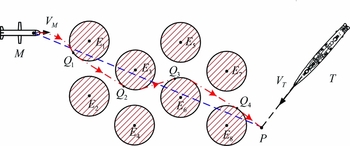
After obtaining the above waypoints, we can guide the missile to the target along a short path satisfying the NFZ constraints. Fig. 13 shows the flowchart of the guidance. To explain the flowchart clearly, an example is given as shown in Fig. 14.
The flow chart of the extended OBPCG.

Sketch of the extended guidance with multiple NFZ constraints.

First, use the previously mentioned iterative method to predict the collision point P. Next, search the NFZs intersecting with MP, whose centers are E 1, E 3, E 6, E 8. Finally, to bypass these NFZs, use the multi-step decision process to build up the waypoints Q 1, Q 2, Q 3, Q 4, and navigate the missile to the target along the path passing through these waypoints.
4.0 SIMULATION RESULTS AND DISCUSSION
4.1 The artificial potential field method
In Reference Peng, Sun, Dong and LiRef. 23, a guidance law was proposed based on APFM for undertaking multi-NFZs-avoiding missions, the results of which are also provided here for comparison. The guidance law assumes that the target generates an attractive force but the NFZs exert repulsive forces on the missile. The artificial potential field model is described by
 $$\begin{equation}
{F_{rk}} = - \frac{{{k_{rk}}{{\left\| {{{{\bf V}}_M}} \right\|}^2}{r_{{E_k}}}\;{\rm{sin}}(\sigma _k^*)}}{{1 + {g_{rk}} + \left| {{g_{rk}}} \right|}},
\end{equation}$$\\
 $$\begin{equation}
{g_{rk}} = {\left\| {\overrightarrow {{E_k}M} } \right\|^2} - r_{{E_k}}^2,
\end{equation}$$\\
 $$\begin{equation}
\sigma _k^* = \left\{ {\begin{array}{@{}*{2}{l}@{}} {0,}&\quad {{\sigma _k} \ge 0}\\ {{\sigma _k},}&\quad {{\sigma _k} < 0} \end{array}} \right.,
\end{equation}$$
 $\overrightarrow {{E_k}M} $
. krk
is the weight coefficient of Frk
. r
Ek
is the radius of the k
th NFZ and σ
k
is the value of σ with respect to the kth NFZ.
 $$\begin{equation}
{F_a} = \frac{{{k_a}{{\left\| {{{{\bf V}}_M}} \right\|}^2}}}{{1 + {g_a} + \left| {{g_a}} \right|}},
\end{equation}$$\\
 $$\begin{equation}
{g_a} = {\left\| {\overrightarrow {MT} } \right\|^2},
\end{equation}$$
 $\overrightarrow {MT} $
, ka
is the weight coefficient of the attractive force generated by the missile.
The resultant force of the missile can be calculated by
 $$\begin{equation}
{{\bf F}} = {{{\bf F}}_a} + \sum\limits_{k = 1}^\Gamma {{{{\bf F}}_{rk}}} ,
\end{equation}$$
where Γ represents the number of the NFZs. The component of F perpendicular to V M is used as the guidance command
 $$\begin{equation}
{{{\bf a}}_c} = \left( {{{\bf F}} \cdot {{{\bf p}}_{{V_M}}}} \right) \cdot {{{\bf p}}_{{V_M}}}/m,
\end{equation}$$
where m is the mass of the missile.
4.2 Simulation results
In case 1, a stationary target is considered and there are eight NFZs with the same radius r = 20 km in combat environment. The initial conditions of the missile are XM = ( − 60, 0) km and
 ${{{\bf V}}_M} = ( {400\sqrt 2 ,} { - 400\sqrt 2 } ){\rm{m}}/{\rm{s}}$
. The target position is XT = (200, −80) km.
Figures 15 and 16 show the trajectory and acceleration command history for OBPCG while Figs 17 and 18 show the trajectory and acceleration history for APFM. As can be seen from these figures, both guidance laws can steer the missile to the target while avoiding the multiple NFZs. However, compared with APFM, the trajectory for OBPCG is much smoother and satisfies all the NFZ constraints strictly. Meanwhile, the acceleration profile for OBPCG is much smaller and smoother than that for APFM. For APFM, the acceleration oscillates violently when the missile gets close to the target. It is because that the artificial potential forces are sensitive to the distances of the missile from the NFZs and target. If the missile is close enough to the target, the attractive force becomes huge and may drag the missile into NFZs. In addition, because the repulsive forces are enormous as well, a small disturbance of the missile would result in a huge change in the magnitude of a c . Thereby, as shown in Fig. 18, the command profile oscillates violently in the terminal phase. Besides, in Table 1, because the trajectory of OBPCG is shorter and smoother than that of APFM, the flight time of the former is also smaller than that of the latter.
The trajectory for OBPCG.

The acceleration command history for OBPCG.

The trajectory for APFM.

The acceleration command history for APFM.

The flight times for OBPCG and APFM in case 1

In case 2, more NFZs are considered and the target maneuvers along the following path:
 $$\begin{equation}
y = A{e^{\frac{x}{T}}}\;{\rm{sin}}\left( { - \frac{\pi }{T}x - \frac{{5\pi }}{8}} \right) - 215,
\end{equation}$$
where A = 300 km, T = 70 km.
In this case, the initial conditions of the missile and target are
 ${{\bf XM}} = ( {60,0} )\;{\rm{km}},\;{{{\bf V}}_M} = ( { - 400\sqrt 2 , - 400\sqrt 2 } )\;{\rm{m}}/{\rm{s}},\;{{\bf X}}{{{\bf T}}_0} = ( { - 170, - 230} )\;{\rm{km}}$
, and VT
0 = ( − 130, 150) m/s. The 15 NFZs are distributed randomly, whose radiuses are unequal and range from 15 km to 36 km.
Figures 19–22 show the simulation results for OBPCG and APFM. From these results, we can see that, even though the target manoeuvers strongly, OBPCG can still guide the missile to intercepting the target successfully along a smooth and short path while satisfying all the NFZ constraints. By contrast, for APFM, the manoeuvering of the target results in violent oscillations of the guidance commands, and thus causes the missile to travel along a longer and more curved trajectory, part of which slightly violates the NFZ constraints. Therefore, as shown in Table 2, the flight time for APFM is also greater than that for OBPCG.
The trajectory for OBPCG.

The acceleration command history for OBPCG.

The trajectory for APFM.

The acceleration command history for APFM.

The flight times for OBPCG and APFM in case 2

In case 3, a special scenario is taken into account where the target gets into an NFZ. In this case, once the target enters the NFZ, the NFZ becomes invalid and is neglected by the guidance. As shown in Fig. 23, the missile is guided into the NFZ directly in order to intercept the target.
Trajectory for the case that the target gets into an NFZ.

In case 4, an example is provided to show the influence of detection errors in the target position and NFZ locations. The initial conditions are
 ${{\bf XM}} = ( { - 40, - 25} )\;{\rm{km}},\;{{{\bf V}}_M} = ( {400\sqrt 2 , - 400\sqrt 2 } ){\rm{m}}/{\rm{s}},\;{{\bf XT}} = ( {100, - 40} ){\rm{km}},\;{{\bf VT}} = ( { - 157, - 200}) {\rm{m}}/{\rm{s}}$
and the target moves along a sinusoidal trajectory. The detection errors in target velocity and position are designed to be small sinusoidal perturbations. Meanwhile, the detection errors in NFZ locations are normally distributed as follows:
 $$\begin{equation}
{{\bf X}}{{{\bf E}}_{{d_k}}} \sim N\left( {{{\bf X}}{{{\bf E}}_k},\sigma _{X{E_k}}^2} \right),
\end{equation}$$
where XE dk is the detected location of the kth NFZ. The mean square error σ XEk can be calculated by
 $$\begin{equation}
{\sigma _{X{E_k}}} = {e_k}\left\| {{{\bf XM}} - {{\bf X}}{{{\bf E}}_k}} \right\|,
\end{equation}$$
where ek is the maximum location error of the kth NFZ. Note that σ XEk gradually decreases as the missile gets close to the boundary of the kth NFZ.
Figures 24 and 25 show that the guidance still performs well even if there are detection errors in the target states and the NFZ locations. The red dash-dot curve with small red circles presents the trace of the predicted collision point. The grey dash circles represent the detected NFZs with measurement errors while the black solid circles represent the real NFZs.
The trajectory for OBPCG in case 4.

The acceleration command history for OBPCG in case 4.

In case 5, we consider the uncertainty in the maximum maneuvering load n
max of the missile. In this case, n
max is adjusted from 10 G to 2 G, which greatly reduces the turning rate and thus increases the difficulty of avoiding the NFZs. Meanwhile, the NFZs are located closely where the narrowest gap is only 5 km. The initial conditions are
 ${{\bf XM}} = ( { - 40,0} )\;{\rm{km}},\;{{{\bf V}}_M} = ( {400\sqrt 2 ,} { - 400\sqrt 2 } ){\rm{m}} / {\rm{s}},\;{{\bf XT}} = ( {145,30} )\;{\rm{km}},$
and VT = (0, −200)m/s. As can be seen in Figs 26 and 27, the guidance law shows a strong robustness to n
max where all the NFZ constraints are satisfied. The larger n
max allows the missile to bypass the NFZs along a shorter path such that the flight time can be decreased. However, if n
max is small, the missile would choose a relatively smoother but longer path to intercept the target.
The trajectory for OBPCG with different n max.

The acceleration command history for OBPCG with different n max.

In addition, we verify the robustness of the guidance law to the damping ratio ξ of BCHS, which varies from 1.0 to 3.0. The initial conditions are
 ${{\bf XM}} = ( { - 40,0} ){\rm{km,}}\;{{{\bf V}}_M} = ( {400\sqrt 2 , - 400\sqrt 2 }) {\rm{m}}/{\rm{s,}}\;{{\bf XT}} = ( {145,20} ){\rm{km}},\;{{\bf VT}} = ( {0, - 200}) {\rm{m/s}}$
. As shown in Figs 28 and 29, the guidance still performs well even if the damping ratio ξ varies largely.
The trajectory for OBPCG with different damping ratio ξ

The acceleration command history for OBPCG with different damping ratio ξ.

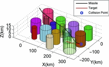
In case 6, a 3-D space simulation is conducted to test the performance of the proposed guidance, where the NFZs are assumed to be cylinders with infinite heights. To handle this case, we still adopt the above 2-D guidance law to control the horizontal movement of the missile and propose a variant of PN to control the motion along altitude.
First, define θ as the slope angle of the flight path and it is calculated by
 $$\begin{equation}
\theta = {\rm{arctan}}\frac{{{h_T} - {h_M}}}{s},
\end{equation}$$
where s is the length of the projection of the curved path onto the horizontal plane and approximated by the sum of the horizontal distances between adjacent waypoints, hT , hM are the altitudes of the target and missile, respectively.
Then, we can obtain the rate of θ by
 $$\begin{equation}
\dot{\theta } = \frac{{\left( {{{\dot{h}}_T} - {{\dot{h}}_M}} \right)s - \left( {{h_T} - {h_M}} \right)\dot{s}}}{{{s^2} + {{\left( {{h_T} - {h_M}} \right)}^2}}},
\end{equation}$$
where the time derivation of s is equal to the component of the missile's velocity pointing towards the next waypoint in the horizontal plane.
Thus, the vertical acceleration of the missile can be obtained by
 $$\begin{equation}
{a_v} = N'{V_c}\dot{\theta },
\end{equation}$$
where N' is the effective navigation ratio (usually in the range of 3–5) and Vc is the missile-target closing velocity.
In this case, fifteen 3-D NFZs are considered and the target is assumed to maneuver along the following path
 $$\begin{equation}
\left\{ {\begin{array}{@{}*{1}{l}@{}} {y = A{e^{ - \frac{x}{T}}}\;{\rm{sin}}\left( {\frac{\pi }{T}x - \frac{{5\pi }}{8}} \right) - 153}\\ {z = 5} \end{array}} \right.,
\end{equation}$$
where A = 300 km, T = 70 km.
In this case, the initial conditions are
 ${{\bf XM}} = ( { - 60,0,15} ){\rm{km,}}\;{{{\bf V}}_M} = ( {400\sqrt 2 , - 400\sqrt 2 ,0}) {\rm{m}}/{\rm{s}},\;{{\bf X}}{{{\bf T}}_0}{\rm{ = }}( {220, - 140,5} ){\rm{km,}}\;{{\bf V}}{{{\bf T}}_0}{\rm{ = }}( {180,40,0}) {\rm{m/s}}$
. The 15 NFZs are distributed randomly and their radiuses vary from 15 km to 36 km.
Figures 30 and 32 show the trajectories generated by OBPCG and APFM, respectively. Figures 31 and 33 show the horizontal projection of the two trajectories. We can see that both OBPCG and APFM can steer the missile to the target. However, the trajectory generated by OBPCG is much smoother than that of APFM. Figures 34 and 35 show the command histories of the horizontal acceleration ah and the vertical acceleration av for the two guidance laws. During the missile bypasses the NFZs, the fluctuation of the acceleration command history for OBPCG is much smaller than that of APFM. And the curved trajectory of APFM results in a longer flight time, as shown in Table 3.
The 3D trajectory for OBPCG.

Horizontal projection of the trajectory.

The 3D trajectory for APFM.

Horizontal projection of the trajectory.

The acceleration command history.

The acceleration command history.

The flight times for OBPCG and APFM in case 3

5.0 CONCLUSION
In this article, a new guidance law is proposed for intercepting time-critical target while avoiding multiple NFZs distributed randomly. The research has two steps. First, a guidance law is designed for single-NFZ avoidance and consists of three parts: OAS based on the predicted collision point, BCHS and PN. Then the guidance is improved by multi-step decision process to address multiple NFZ constraints. The effectiveness of OBPCG has been demonstrated by the trajectory simulations. As can be seen from the results, in contrast to the artificial potential field method, the proposed guidance law has a high accuracy, requires small maneuvering loads, and thus achieves a smooth trajectory.
CONFLICT OF INTEREST STATEMENT
There is no conflict of interest in this work.