I. INTRODUCTION
Since Howatt first used tape casting to prepare ceramics in 1947,Reference Howatt, Breckenridge and Brownlow1 tape casting has been considered a promising method for producing thin and flat ceramic sheets with numerous applications in the electronic industries (e.g., substrates,Reference Chartier and Bruneau2 microelectronics,Reference Tok, Boey and Khor3 transducer,Reference Mistler4 piezoelectric transformers,Reference Jantunen, Hu, Uusimäki and Leppävuori5 capacitors,Reference Sakabe6 etc.), solid oxide fuel cells,Reference Wang, Qian, Cao, Wang and Wen7 structural materials, multilayer packages,Reference Sakabe6,Reference Blodgett and Barbour8 and rapid prototyping.Reference Cui, Ouyang, Yu, Wang and Huang9 The thin, flat ceramics can also be patterned, stacked, and laminated to form three-dimensional structures. In terms of the medium used to form slurries, tape casting has been classified into two categories: nonaqueous and aqueous tape casting.Reference Antolini, Ferretti and Gemme10–Reference Mikeska and Cannon12 Nonaqueous media have been used for industrial production, with benefits including low boiling points, easy evaporation, low surface tension, hydration prohibition, and shortened production time. However, precautions concerning toxicity, flammability, explosiveness, and volatility exist for nearly all nonaqueous media. Because of these drawbacks of nonaqueous media, much attention has been recently focused on water-based systems, which are more cost-effective and less hazardous. Aqueous tape casting has several disadvantages, including low tape green strength, slow drying rate, heightened crack sensitivity, possible material reactivity with water, and increased agglomeration due to hydrogen bonding. Although the disadvantages of aqueous systems has limited their applicability, many efforts have been devoted to improve aqueous tape casting by optimizing solid loading, and adding dispersants together with plasticizers. The development of aqueous tape casting has been the subject of recent research studies with several different binders, including acrylic latex,Reference Kristoffersson and Carlström13 acrylic emulsion,Reference Doreau, Tarı̀, Pagnoux, Chartier and Ferreira14 cellulose ethers,Reference Gurak, Josty and Thompson15 polyvinyl alcohols,Reference Adolfsson16 and acrylic polymers.Reference Nagata17
To achieve dense and homogeneous ceramic sheets, tape casting slurries must be uniformly dispersed and well stabilized. The viscosity, solid loading, and shear thinning behavior of the slurry have significant impacts on the shrinkages during the drying and subsequent densification process. Because of these requirements, water soluble dispersants were adopted to achieve steric and electrostatic stabilization.Reference Chartier and Bruneau2,Reference Albano and Garrido18–Reference Moreno20 Several studies have shown that some binders also exhibit dispersion effects in the slurry.Reference Schelffele, Sacks, Blum and Cannon21,Reference Jean, Yeh and Chen22 Recently, a gelling agent known as ISOBAM has been shown to have spontaneous function both as a dispersant and as a gelling agent for ceramic powders. As such, ISOBAM has promise as an environment-friendly and simple gel-casting system for ceramic processing.Reference Shimai, Yang, Wang and Kamiya23–Reference Sun, Shimai, Peng, Zhou, Kamiya and Wang29 In addition, ISOBAM also functions as a binder for ceramic powders. ISOBAM is water-soluble, nontoxic, and a low-cost organic compound, which makes it an ideal candidate for aqueous tape casting. In this work, ISOBAM was studied both as a dispersant and as a binder for the tape-casting process.
II. EXPERIMENTAL
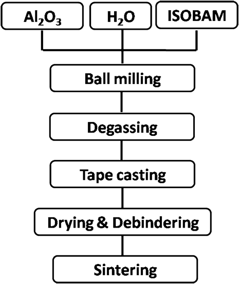
Commercial Al2O3 powders (Baikowski, Annecy, France, D 50 = 0.45 μm) were used as raw materials. A water solvable copolymer of isobutylene and maleic anhydride, with a commercial name of ISOBAM and a density of 1.3 g/cm3 (M.W. = 160,000–300,000, Kuraray Co., Ltd.), was used both as a binder and as a dispersant. Tape casting slurries were prepared with Al2O3 powder, ISOBAM, and distilled water by ball-milling to achieve homogeneous dispersion of the components. Slurries with different binder levels and solid loadings were prepared. The viscosity of the slurries was investigated to understand the effect of the variables on rheological behaviors, using a stress-controlled rheometer (TA Instrument AR2000 Rheometer). Viscosity measurements were performed by preshearing the slurry at 100 s−1 for 30 s and increasing the shear rate continuously from 0.001 to 200 s−1. The experimental process for producing wafers is shown in Fig. 1, as is much simpler than many other tape casting systems.Reference Kristoffersson and Carlström13,Reference Snijkers, De Wilde, Mullens and Luyten30–Reference Yuping, Dongliang and Greil33 After degassing, the Al2O3 slurries were tape-casted with a moving blade at a speed of 25 mm/min on a stationary polypropylene carrier film (Mylar) with blade gaps 0.5 and 1.5 mm. After demolding and drying, the debinding and presintering of the green sheets were carried out with heating rates of 3–5 °C/min to 1000 °C for 3–5 h. The final alumina ceramics were sintered in a vacuum furnace (10−5–10−6 MPa) in the temperature range of 1750–1850 °C for 5 h with a heating rate of 10 °C/min.
Flowchart of procedure for manufacturing transparent Al2O3 by tape casting and vacuum sintering.

The morphology, as well as the fracture surface and as-sintered surface of Al2O3 powders was observed using a scanning electron microscope (SEM, Quanta 200F, FEI). The particle size distribution was tested using x-ray (SediGraph III Plus, Micromeritics, Georgia). The microstructures of the fracture and surface of vacuum-sintered Al2O3 ceramics were examined by SEM (Quanta 200F, FEI) together with the in-line transmittance in the ultraviolet-visible light region using UV-vis spectrometer (Perkin Elmer Lambda 950, Massachusetts) and the infrared region tested using Fourier transform infrared spectrometer (Nicolet 6700, Thermo Fisher Scientific Corporation, Waltham, MA).
III. RESULTS AND DISCUSSION
A. Powder characterization
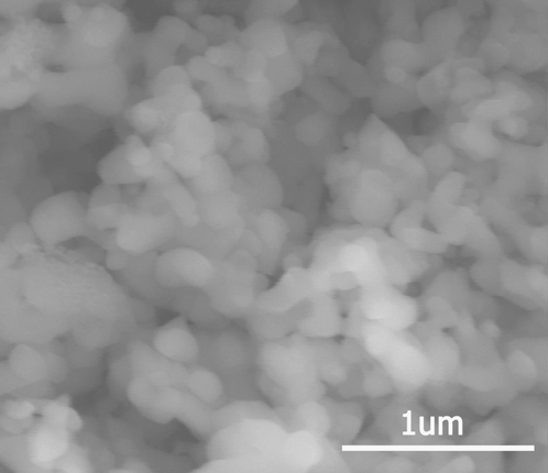
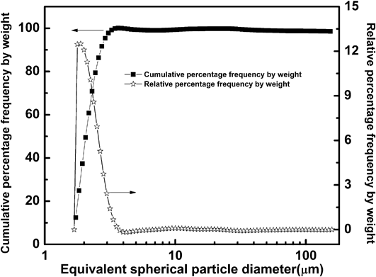
Figure 2 exhibits morphology of commercial Al2O3 powders show the particle size distribution in the range of 0.05–0.8 μm. Agglomerations in the powder are apparent, which further reinforces the necessity of ball milling to achieve slurry homogeneity. Particle size and distribution measurements of the powder show both an equivalent spherical diameter of powder <4 μm, and a median particle size (D 50) of 1.8 μm (Fig. 3). The particle size and distribution measurement shows a larger mean particle size and larger equivalent spherical particle size than that indicated in SEM examination. It can be considered as a further evidence for Al2O3 particle agglomeration.
Particle morphology image of Al2O3 powder CR-10.
Particle size distribution of Al2O3 powder.
B. Rheological properties of Al2O3 slurries
The rheological behavior of the slurries is influenced by ceramic powders, as well as binder, solvent, and other organic additives that are used. However, the most important factor is binder addition level.Reference Pagnoux, Chartier, de F Granja, Doreau, Ferreira and Baumard19,Reference Hotza and Greil34 The influence of the high surface tension of water, as well as limited solubility of binders also need to be considered in aqueous system. To decrease the deformation and defects during the drying and firing process, the water and binder content should be as low as possible, as water and organic additives need to be removed before final sintering. Here, the rheological behaviors of the slurries were examined as a function of binder level and solid loading.
1. Viscosity of Al2O3 slurries with respect to binder addition
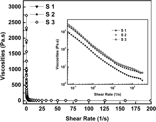
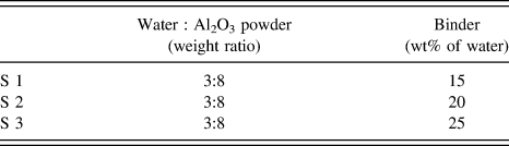
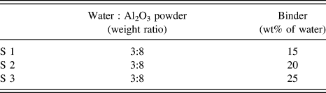
The rheological properties of Al2O3 slurries (weight ratio of water : Al2O3 powder = 3:8) were examined by analyzing the changes in viscosity over binder addition level in the range of 15–25 wt% (water based) at 25 °C in air, as shown in Fig. 4. The slurry compositions are listed in Table I. The viscosity curve in the inset of Fig. 4 shows that these Al2O3 slurries exhibit shear thinning behavior (pseudoplasticity) at shear rates in the range of 0.05–200 s−1, which is similar to other reports.Reference Shimai, Yang, Wang and Kamiya23,Reference Yang, Shimai and Wang25,Reference Yang, Wu, Tustison and Zelinski26 During the tape casting process, the doctor blade moves at a speed of 25 mm/min to ensure minimal influences of shear rate changes on the viscosity, which is decided by the gradient of viscosity versus shear rateReference Bitterlich, Lutz and Roosen35 in Fig. 4. Pseudoplasticity behavior is crucial for the tape casting process for the following reasons: (1) High shear rates produce low viscosities to ensure the homogeneous mass flow in the slurries; (2) Moving doctor blade could produce enough shear force to decrease the viscosity followed by a rapid increase after the blade stops to suppress uncontrolled flow and sedimentation of ceramic powders. In Fig. 4, the viscosity of slurries increases with binder addition level in the range from 15 to 20 wt%, while remaining relatively constant over the range of 20–25 wt%. It could be found that when binder addition was <20 wt%, the binder addition level has a large influence on the rheological behavior while a minor influence when it was 20 wt% or greater. Therefore, 20 wt% is an ideal level of binder addition for the tape casting process.
Viscosity of Al2O3 slurries varying with binder addition (water based) and with solid loading 68 wt%.
Composition of tape casting slurries.
2. Viscosity of Al2O3 slurries varying with solid loadings
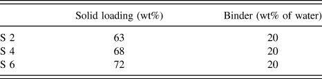
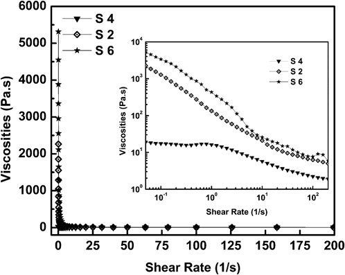
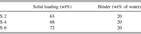
The composition of Al2O3 slurries with different solid loadings is shown in Table II. The viscosity of Al2O3 slurries was examined as a function of solid loading, as shown in Fig. 5. From the viscosity curves, it could be seen that all the Al2O3 slurries show the shear thinning process (pseudoplasticity), similar to the rheological behaviors of the suspensions, as shown in the inset of Fig. 4. The viscosity shows a large increase over the range of 63–72 wt%. High solid loading is desirable in the tape casting process, as it helps to keep the shape of casted tape and reduce drying shrinkage, deformation, and cracks. The slurry viscosity with a solid loading of 63 wt% is as low as 25 Pa s during the shearing process, which may introduce flow receding in the tapes. This may also cause droplet formation, the larger shrinkage and more complex drying process. Whereas, over high solid loading could cause very high viscosity and trap the bubbles during the degassing process. The viscosity of Al2O3 slurry with a solid loading of 72 wt% was as high as 32,000 Pa s, which made it difficult to mix by ball-milling and the following casting process. However, the slurries with a solid loading of 68 wt% showed moderate viscosity, which is suitable for this tape casting process. Based on the discussion above, the Al2O3 slurry with 20 wt% binder addition level and 68 wt% solid loading was adopted for the tape casting process under doctor blade moving speed 25 mm/min.
Composition of tape casting slurries.
Viscosity of Al2O3 slurries varying with different solid loadings and with binder addition 20 wt%.
3. Characterization of Al2O3 green tapes
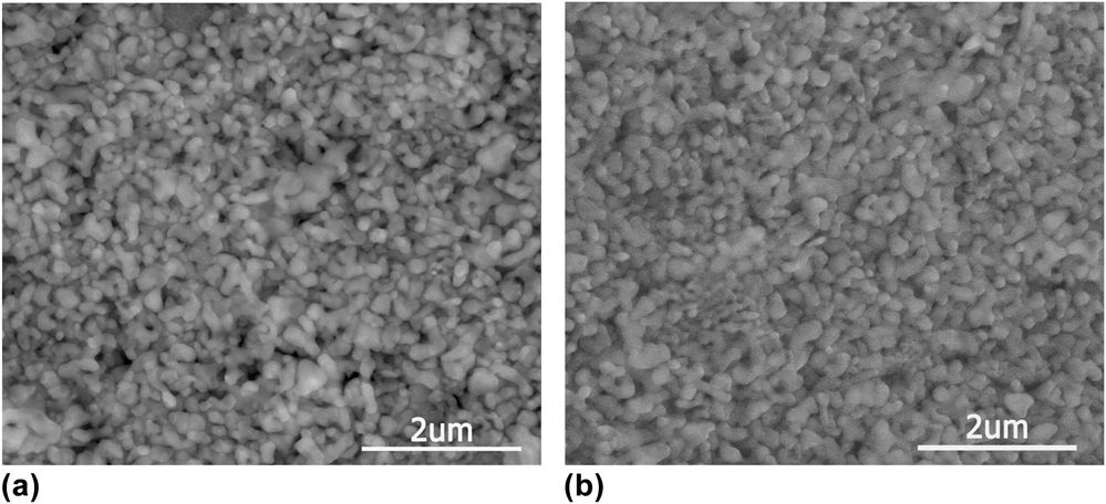
To improve the plasticity and workability of the green tapes, plasticizers were added to improve the flexibility of the tapes. Photographs of good quality green tapes casted with a solid loading of 68 wt% and binder addition level of 20 wt% are shown in Fig. 6. The Al2O3 green tapes were flexible, easy to handle, and without any cracks under freely bending. The microstructures of Al2O3 tape surfaces, derived from the slurries containing 68 wt% solid loading with 20 wt% binder addition, before and after the debindering process are shown in Fig. 7. It can be observed that uniform green body was achieved by the ISOBAM tape casting process. Al2O3 particles are homogeneously distributed and encapsulated by binders after tape casting, without any agglomerations, giving rise to improved density and strength of the green tape. The binder burnout process was performed at a heating rate of 2–5 °C/min without defects (e.g., deformation, blister, cracks, etc.) commonly observed with excessive heating rates in other tape casting processes,Reference Kristoffersson and Carlström13,Reference Kristoffersson, Roncari and Galassi36 which shortens the debindering process and saves production time and energy. During the debinding process, packing density was increased through the removal of all organic material with tapes, as shown in Fig. 7. The particle sizes changed little during the debinding process.
Photos of Al2O3 green tape after casting in air at room temperature: (a) flat green tape; (b) flexible green tape.
Microstructures of Al2O3 green tape (a) before and (b) after debinding process.
4. Vacuum sintering of transparent Al2O3 tape
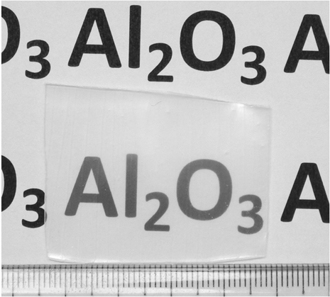
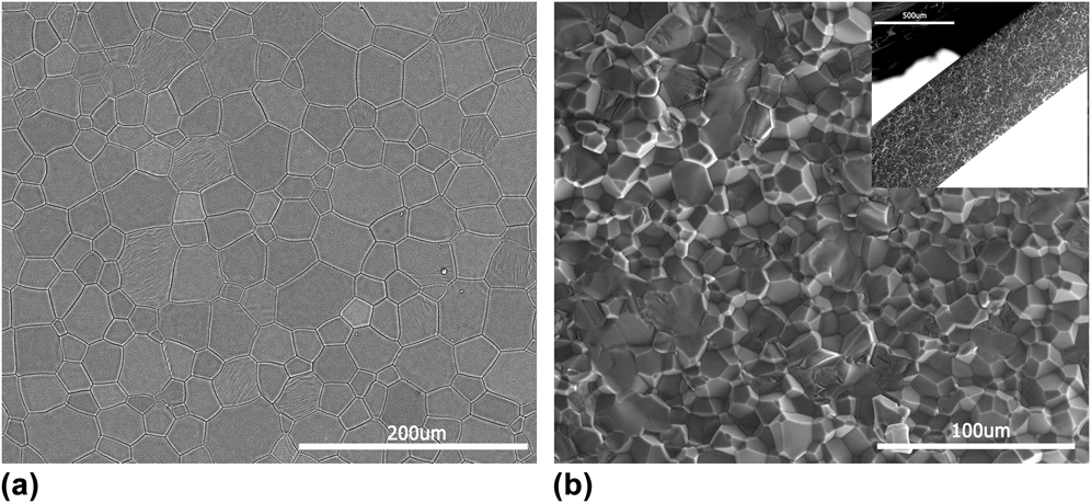
Transparent Al2O3 wafers were achieved by final vacuum sintering at 1750−1850 °C holding for 3–5 h (Fig. 8). The obtained transparent Al2O3 wafers show good quality and defect-free surfaces. Figure 9 shows the as-sintered surface and fracture microstructures of transparent Al2O3 wafers. The main grain size distribution lies in the range of 20–80 μm. No obvious differences are observed in the microstructure of Al2O3 wafers between casting direction, transverse-to-casting direction, and thickness direction. The grains compact together very tightly without any pores on the grains or grain boundaries in the surface or fracture plane. In Fig. 9(b), transparent Al2O3 wafers are dominated by intergranular fracture with minor intracrystalline rupture. The sintered thickness of a wafer is shown to be about 660 μm in the inset of Fig. 9(b).
Photo of transparent Al2O3 ceramics.
Microstructures of transparent Al2O3 ceramics: (a) as-sintered surface and (b) fracture surface.
5. Transmittance test of tape-casted and vacuum-sintered transparent Al2O3 wafers
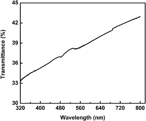
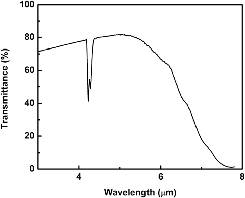
The in-line transmittance of tape-casted and vacuum-sintered transparent Al2O3 wafers without polishing was characterized in the UV-vis region (200–800 nm) in Fig. 10 and the IR region (3–10 μm) in Fig. 11. In the UV-vis region, the in-line transmittance increases gradually from 33% to 43% (Fig. 10) with increasing incident light wave length. The transmittance of transparent Al2O3 (without polishing) at 600 nm is about 39%, better than results of epoxy resin gelcasted translucent Al2O3.Reference Shimai, Yang, Wang and Kamiya23,Reference Mao, Shimai, Dong and Wang37 In the IR region (3–10 μm), the in-line transmittance has a value of 82% at 5 μm (Fig. 11), which increases between 3–5 μm and decreases over the range of 5–8 μm. An obvious absorption peak at 4.2 μm might come from the C–O bonding stretching.Reference Wenig and Schrader38
In-line transmittance of transparent Al2O3 (thickness: 660 μm, no polishing) in the UV-vis region.
In-line transmittance of transparent Al2O3 (thickness: 660 μm, no polishing) in the IR region.
IV. CONCLUSION
Transparent Al2O3 wafers were fabricated by tape casting with a new environmentally friendly binder (ISOBAM) followed by vacuum sintering techniques. The binder ISOBAM could function both as a dispersant and as a binder for the tape casting process. A binder addition level of 20 wt% and a solid loading of 68 wt% Al2O3 were found to be optimum conditions for aqueous tape casting and production of flexible green tapes. Green tape with good plasticity was made successfully. After the debinding and vacuum sintering process, transparent Al2O3 wafers with transmittance of 39% at 600 nm and 82% at 5 μm were successfully produced. Average grain size of final wafers is about 10–80 μm without apparent pores microstructures. The results indicate that environmentally friendly ISOBAM could be potentially applied for tape casting of transparent ceramics.
ACKNOWLEDGMENTS
We gratefully acknowledge the Air Force Office of Scientific Research (AFOSR) (Contract FA9550-10-1-0067) for funding and supporting this research.