Introduction
Benchmark perovskite photovoltaic devices already achieve power conversion efficiency (PCE) figures over 20%, which is comparable to those of established solar cell technologies, such as silicon solar cells [Reference Green, Hishikawa, Dunlop, Levi, Hohl-Ebinger and Ho-Baillie1]. Although the performance of perovskite solar cells is competitive, the toxicity of the widely used lead compounds and their solvents used for solution processing is still problematic [Reference Babayigit, Ethirajan, Muller and Conings2]. To tackle the first aspect, less toxic alternative systems, like Sn- or Bi-based perovskites, have been considered [Reference Giustino and Snaith3]. Sn-based solar cells reach PCE up to 6% but suffer from a pronounced instability under ambient conditions [Reference Hoye, Brandt, Osherov, Stevanović, Stranks, Wilson, Kim, Akey, Perkins, Kurchin, Poindexter, Wang, Bawendi, Bulović and Buonassisi4]. In contrast to Sn-based perovskites, Bi-based compounds are stable over days under such conditions [Reference Hu, Dong and Zhang5]. However, due to the poor coverage of solution-processed Bi-based perovskites, PCEs remain rather low, rarely overcoming the threshold of 1%. Recently, Zhang et al. demonstrated a significant performance boost of Bi-based perovskite solar cells by employing vapor deposition of the precursors methylammonium iodide (MAI) and bismuth iodide (BiI3). By using a two-step method, high-density layers with enhanced coverage and relatively large grain sizes have been achieved. As a result, methylammonium bismuth iodide (MBI) solar cells fabricated by vapor deposition reached a record PCE of 1.64% [Reference Zhang, Li, Xia, Wang, Huang, Lei and Gao6]. In this work, chemical vapor deposition (CVD) of MBI as an environmentally friendly, solvent-free deposition technology and its application to solar cell fabrication are discussed. Both precursors, MAI and BiI3, are deposited in an alternating deposition sequence, in which substrate temperatures and the cycle times of both precursors are varied, with the aim forming dense and coherent layers with large grain sizes. Finally, the CVD layers are integrated into solar cells and their performance figures are compared with those of the cells fabricated by spin-coating.
Theory and process
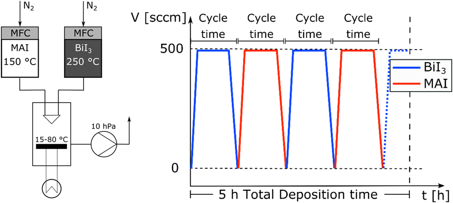
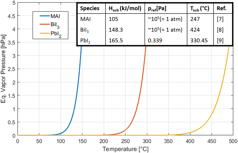
A schematic representation of our CVD system is shown in Fig. 1. The evaporation source for BiI3 consists of a thermal evaporator mounted in a heated tube. For the evaporation of MAI, a heated bubbler-type evaporation source has been employed. To adjust the BiI3 source for sufficient mass transport of the precursor, we rely on our previous study, in which the applicability of CVD for the fabrication of methylammonium lead iodide films has been demonstrated in a similar setup. There, the evaporation of lead iodide was optimized at a temperature of 410 °C [Reference Stümmler, Sanders, Pfeiffer, Weingarten, Vescan and Kalisch7]. In advance to the deposition experiments, equilibrium vapor pressures have been calculated for various precursors by using the Clausius–Clapeyron equation (Fig. 2). Values for sublimation enthalpies and reference pressures have been obtained from literature [Reference Dualeh, Gao, Seok, Nazeeruddin and Grätzel8, Reference Kim and Blairs9, Reference Costa, Azevedo, Santos and Mendes10]. Consequently, the source temperature of BiI3 has been set to 250 °C to reach a similar equilibrium vapor pressure to that of the Pb-based precursor. The source temperature of MAI has been set to 150 °C, which is the same as in a previous study [Reference Stümmler, Sanders, Pfeiffer, Weingarten, Vescan and Kalisch7]. A low Reynolds number is estimated for the process. The velocity of the carrier gas flow as well as the density of the carrier gas can be computed using the ideal gas formula. The inner pipe radius of the runline is 2.29 mm. By using Sutherland’s formula [Reference White11] for estimating the temperature-dependent viscosity of nitrogen, a Reynolds number between 95 and 172 can be calculated in the temperature regime between 20 °C and 400 °C (see Supplementary material for details). Therefore, a laminar flow regime can be assumed for the deposition of MBI. As a consequence, incomplete intermixing of both precursor flows before introduction into the deposition chamber is expected in the case of a simultaneous MAI + BiI3 process, affecting homogeneity of deposition. Furthermore, pre-reactions of both precursors might lead to particle formation in the gas phase, which has previously been found for the perovskite methylammonium lead iodide in a similar process. Consequently, all CVD experiments are carried out as alternating deposition runs—both precursors are deposited consecutively over repeated periods (deposition cycles) (Fig. 1, right). In order to enhance the penetration process of MAI into the BiI3 matrix and the subsequent reaction, each deposition experiment starts with a deposition cycle of BiI3, as explained in detail in the discussion section. These cycles are repeated until a total deposition time of 5 h is reached. Although crystal formation of perovskites is well understood for films fabricated by solution processing, especially for the compound MBI, film formation when deposited from the vapor phase and the determining factors for the structural properties have been only investigated superficially. Recently, Chen et al. examined vapor deposition of MBI in a heated tube furnace [Reference Chen, Myung, Thind, Gao, Yin, Shen, Cho, Cheng, Sadtler, Mishra and Banerjee12]. They proposed that even when both precursors are deposited simultaneously, the reaction mechanism is characterized by the intercalation of MAI molecules into a BiI3 matrix. It was argued that the free Gibbs energy of condensation of MAI is low compared to that of BiI3, resulting in pronounced re-evaporation and high concentration of MAI in the vapor phase. As a result, the reaction to MBI is dominated by a gas–solid interaction of MAI and BiI3. Recently, the enthalpies of formation for various lead-containing perovskites have been calculated by Nagabhushana et al., showing a strong dependence between stability and formation enthalpy [Reference Nagabhushana, Shivaramaiah and Navrotsky13]. MBI, known for its high stability, is therefore expected to have a large enthalpy of formation as well. Moreover, comparing MBI with other perovskites with pronounced stability, like methylammonium lead chloride, a relatively high activation energy for the formation of MBI can be deduced. This implies in turn that the substrate temperature should have a particularly strong effect on the crystallite growth rate. The reaction type of organo-halide perovskites is often estimated to be of first order [Reference Wang, Young Wong, Xiao and Chen14]. Although no experimental data about the reaction type of MBI exist, it can be assumed that the reaction order is equal to or higher than one. In consequence, a positive relationship between reaction rate and concentration of the compounds is expected. In conclusion, the following reaction sequence is proposed for the alternating deposition of MBI via CVD:
(i) Deposition of BiI3.
(ii) Deposition of excessive MAI and penetration into the BiI3 matrix. Formation of MBI.
(iii) Repeated deposition of BiI3, in which excess MAI is either re-evaporated from the surface or directly consumed for perovskite formation.
Process scheme of the CVD of MBI (left). Schematic representation of the alternating deposition of MBI (right).

Calculated equilibrium vapor pressures of the perovskite precursors MAI, BiI3, and PbI2. Values for the sublimation enthalpy H sub as well as for the sublimation temperature T sub and its corresponding reference pressure p ref used for calculation are provided in the table.

The proposed reaction scheme assumes that it is stoichiometrically self-controlled, since any excess amount of MAI is easily evaporated. Consequently, a strong impact of the substrate temperature and the cycle time on MBI crystal growth is expected, and both are identified as the main process parameters in this work.
Discussion
Single one-cycle deposition experiments of MAI and BiI3 alone are conducted to determine their deposition rates and the initial crystal formation of the BiI3 matrix layer. The details of MAI deposition have been investigated in an earlier study and can be found elsewhere [Reference Stümmler, Sanders, Pfeiffer, Weingarten, Vescan and Kalisch7]. Briefly, MAI deposition on FTO (fluorine-doped tin oxide) leads to homogeneous layers at 15 °C substrate temperature, and deposition rates are approximately 300 nm/h.
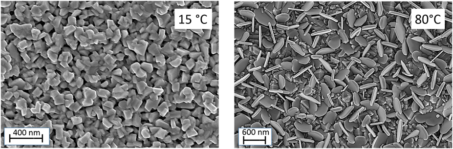
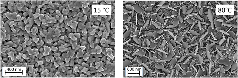
BiI3 was deposited on FTO substrates at substrate temperatures between 15 and 80 °C in this work (Fig. 3). The deposition rate was measured to be around 60 nm/h for all single deposition experiments conducted. The large difference between the deposition rates of both precursors can be attributed to the significantly higher vapor pressure of MAI. BiI3 crystals change their appearance from cubic-shaped to flat-shaped crystallites when the substrate temperature is increased from 15 to 80 °C. In general, porous layers of BiI3 are formed when deposited via CVD. This is expected to be beneficial for the complete conversion to MBI since the penetration of MAI molecules into the BiI3 layer is enhanced.
SEM images of single layers of BiI3 deposited at different substrate temperatures.
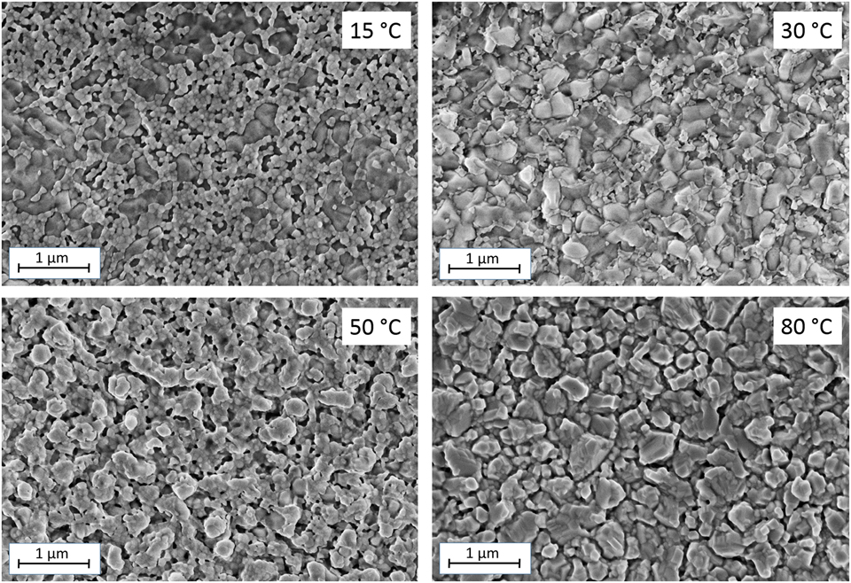
To investigate the influence of the substrate temperature on film formation, MBI layers have been deposited with symmetric deposition cycles of 1800 s and temperatures of 15, 30, 50, and 80 °C (Fig. 4) for 5 h. As mentioned above, each MBI CVD experiment started with a cycle of BiI3 deposition. The total MBI deposition rates have been determined to be approximately 40 nm/h for all substrate temperatures (layer thicknesses around 200 nm). Compared with the single deposition experiments, this is significantly lower than the average deposition rate (180 nm/h) of both precursors. On the other hand, the MBI deposition rate measured is higher than the case in which only BiI3 would have been deposited for 50% of the deposition time. This result suggests that MAI is continuously re-evaporated from the surface throughout the process, in agreement with the proposed reaction scheme. Furthermore, MBI formation is limited by the deposition rate of BiI3.
SEM images of MBI layers deposited at different substrate temperatures.

At lower temperatures (15 °C), the MBI layer consists of smaller particles (50–100 nm), which are visible in the scanning electron microscopy (SEM) image. Additionally, larger dark spots can be observed, indicating substrate areas that remain uncovered. MBI layers deposited at 15 °C are highly porous, and films are not closed. According to the proposed reaction scheme, low substrate temperatures might be not sufficient to re-evaporate MAI properly from the surface. Higher substrate temperatures lead to enhanced crystal growth and more coherent films. At a substrate temperature of 80 °C, the largest crystallites (up to 1 µm in size) and films with enhanced uniformity are obtained, while at substrate temperatures of 30 and 50 °C, smaller crystallites can be still seen in the SEM pictures. This supports the previously stated assumption of a high activation energy for MBI formation and a temperature-dependent reaction rate according to the supposed reaction of first order. In conclusion, a substrate temperature of 80 °C is optimal for MBI formation in this setup to foster MBI crystal growth and to enhance re-evaporation of excess MAI, improving the stoichiometry of the entire process.
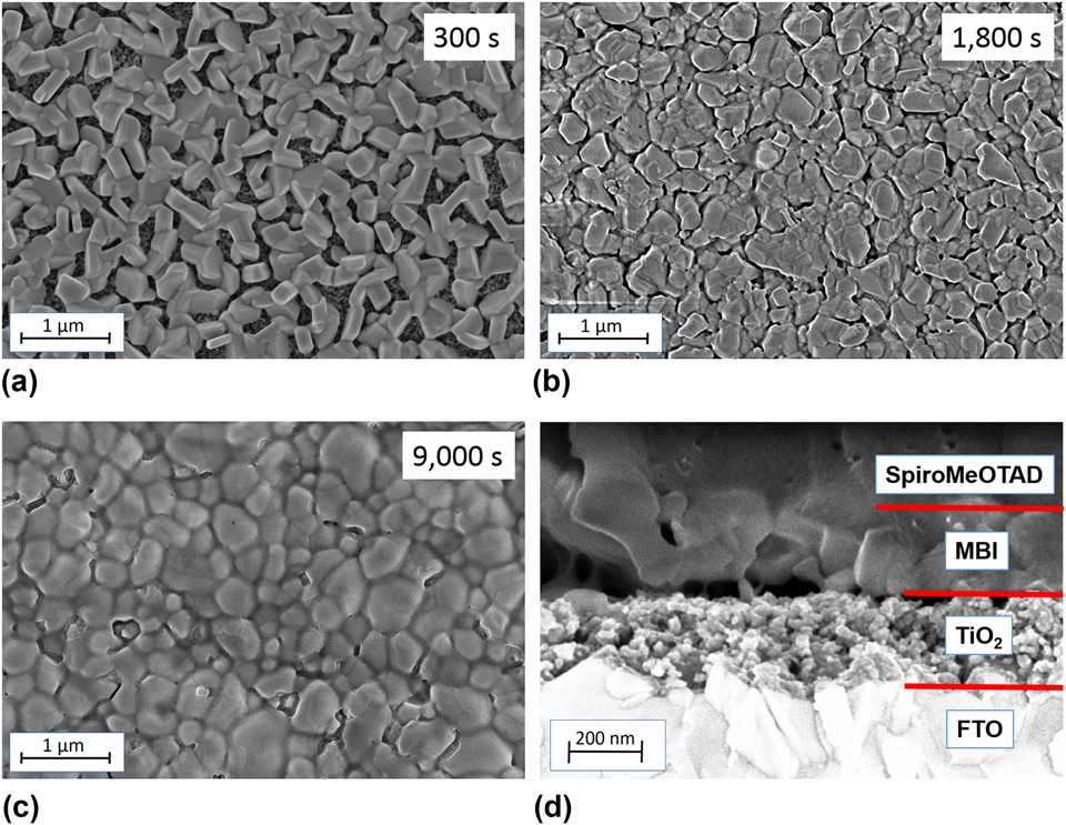
Subsequently, different deposition cycle times have been investigated using the previously determined optimal substrate temperature of 80 °C. Again, layers with thicknesses around 200 nm have been obtained. SEM images of the three samples processed with deposition cycles of 300, 1800, and 9000 s reveal that the coverage of MBI layers is enhanced with longer cycle times (Fig. 5). MBI nuclei grow preferentially in vertical direction for shorter cycles. From literature, it is known that BiI3 tends to grow in vertical direction when deposited at elevated temperatures [Reference Cuña, Aguiar, Gancharov, Pérez and Fornaro15]. Thus, when BiI3 is deposited at 80 °C before it is converted to MBI, crystals perpendicularly oriented to the surface are formed. Under MAI exposure, MBI crystals grow in lateral direction, closing the gaps between the crystallites.
(a–d) MBI layers deposited with different cycle times. (d) SEM cross-section image showing large voids between the MBI and mesoporous titanium dioxide layer.

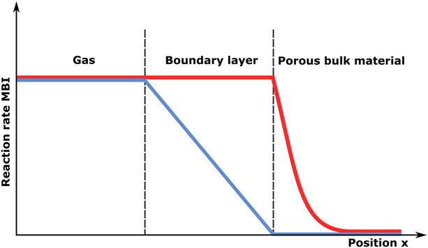
Cross-section images of the CVD MBI layers show large voids of MBI at the interface to the titanium dioxide layer [Fig. 5(d)]. While the layers are closed and conformal structures are achieved at the top of the layer stack, coalescence between the crystal grains of MBI is incomplete at the bottom. Moreover, this also means that MBI does not penetrate into the titanium dioxide matrix, and therefore, the contact area between both layers is drastically reduced compared with conventional solution-processed perovskite films. Incomplete coalescence of the MBI crystallites can be explained by the reaction kinetics, which are dominated by the gas–solid interaction of MAI and the BiI3 matrix. Since the reaction to MBI is estimated to be of first order, it is approximately linearly dependent on the gas phase concentration of MAI. MAI has to be transported from the gas phase to the fluid dynamic boundary layer and finally to the surface of BiI3, from which it diffuses into the porous BiI3 structure. This in turn leads to a concentration profile of MAI across the boundary layer, which depends on the process limiting mechanism. Two extreme cases have to be distinguished in this reaction model [Reference Levenspiel16]. When the reaction rate is significantly higher than the diffusion, all MAI transported to the surface is immediately consumed at the top of the BiI3 layer. As a result, reaction mainly takes place at a continuously propagating MBI/BiI3 interface from the top to the bottom (Fig. 6, blue). When the reaction rate is significantly slower than the diffusion, MAI penetrates into the BiI3 matrix, leading to a vertically diminishing concentration of MAI. If pore diffusion is assumed to be the dominant transport mechanism, this concentration drop can be described by an exponential function (Fig. 6, red). For the reaction type of first order, concentration and reaction rate are linearly related. In consequence, the concentration profile translates to a vertically decreasing reaction rate. In both cases (and therefore in any intermediate case, too), reactions take place primarily at the top of the MBI layer. This in turn explains why layers are closed at the top but not at the bottom. Moreover, the difference of the top and bottom reaction rate is more pronounced with increased layer thicknesses of BiI3 and thus in processes with longer deposition cycles. Furthermore, as the MAI cycle time is increased simultaneously, extended MAI exposure allows for a closed layer surface. In consequence, samples with very long deposition cycles tend to have dense surfaces with coherent crystal structures, while samples deposited at shorter deposition cycles remain partly uncovered.
Reaction rate profile of MBI reaction under diffusion limitation (blue) and reaction rate limitation (red).

Methylamine, a decomposition product of MAI, may also contribute to the smoothening of the MBI surface. Recently, Zhou et al. discovered the beneficial effect of methylamine gas treatment on solution-processed perovskites [Reference Zhou and Padture17]. After annealing in methylamine atmosphere, crystal grain size increased and the surface coverage was enhanced. In addition, the beneficial effect of methylamine addition to an MBI solution for the formation of large crystallites was recently investigated by Li et al. [Reference Li, Wu, Yan, Chi, Pu, Li and Priya18]. In the setup used in this work, MAI is always readily heated to 150 °C, even when the carrier gas is turned off. Decomposition of MAI would result in the formation of methylamine and hydrogen iodide, which accumulate inside the MAI source [Reference Dualeh, Gao, Seok, Nazeeruddin and Grätzel8]. After heating, remaining MAI inside the evaporation source changes its appearance from a white to an orange colored powder, which can also be found downstream in the process pump filter. Although no data about the exact decomposition temperature of MAI exist yet, we assign this color change to decomposition product hydrogen iodide. HI is known to intercalate well into solids [Reference Ma, Islam, Shim, Gu, Wang, Li, Sun, Yang and Kanatzidis19], presumably also in MAI powder, causing the observed color change. In turn, significant amounts of methylamine have to be formed as well. Accumulated methylamine is then released when the carrier gas is turned on and might improve crystal formation of MBI. With longer deposition cycles, a larger amount of methylamine accumulates in the source container, leading to higher gas concentrations and finally to smoother films when released simultaneously with MAI.
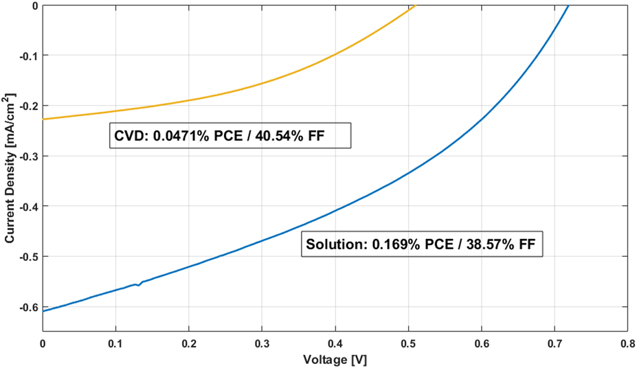
Solution-processed MBI films consist of needle-shaped crystals oriented in parallel to the substrate surface (not shown here). Their appearance differs significantly from that of the CVD samples. Limited contact areas between the crystals lead to low fill factors and shunt resistances. Best devices fabricated from solution in this work show short-circuit currents, which are of the same magnitude compared with literature [Reference Liang and Gao20]. Solar cells with CVD MBI possess significantly lower currents but higher fill factors (Fig. 7). While higher fill factors can be explained by closed layers of MBI preventing shunts between the titanium dioxide and the hole transport layer, lower currents originate from the poor contact between MBI and titanium dioxide as well as the missing penetration of MBI into the porous titanium dioxide layer leading to a lower effective contact area. Moreover, the exciton diffusion length in MBI is significantly lower than that in methylammonium lead iodide [Reference Lyu, Yun, Cai, Jiao, Bernhardt, Zhang, Wang, Du, Wang, Liu and Wang21]. Therefore, the gaps of MBI at the interface and the poor contact have a stronger negative impact on the short-circuit current of the devices. As a consequence, the largest PCE of a solar cell with CVD MBI was 0.0471%, while the best cell with solution-processed MBI achieved a PCE of 0.169% (Fig. 7).
I–V curves of the best CVD-processed and solution-processed cells.

Conclusion
The applicability of CVD for the fabrication of MBI solar cells has been demonstrated in this work. An alternating deposition process of the precursors MAI and BiI3 was employed to obtain the desired perovskite structure. Comparison of deposition rates obtained from the single depositions of MAI and BiI3 reveals that MAI deposited in excess is re-evaporated within the process, facilitating the stoichiometric self-control of the process. Substrate temperature and the deposition cycle time play a major role for the crystal structure of the perovskite. While higher substrate temperatures enhance growth of the crystallites, longer deposition cycles lead to closed and coherent layers at the surface. Cross-section images of the perovskite layers show large gaps at the MBI/titanium dioxide interface. These structural voids can be explained by the reaction mechanisms, which are dominated by diffusion and transport of MAI into the BiI3 matrix. Spatial differences of the MAI vapor concentration lead to inhomogeneous reaction rates and smaller crystallites at the bottom of the MBI layer. As a result, the short-circuit current and the PCE of the solar cells with CVD MBI remain low compared with those of their solution-processed counterparts. Future experiments should aim for a better contact between the active layer and the titanium dioxide. In this context, unsymmetrical cycle times of both precursors could be examined as well as different deposition rates. Moreover, higher substrate temperatures above 80 °C might enhance the crystal growth further, and the effect of methylamine gas on the perovskite layer should be investigated in detail. In addition, alternative approaches such as inverted or planar device architectures should be considered. This would enable process improvements, including vapor-deposited organic transport layers as well as fully vacuum processed solar cells without exposure to ambient air.
Methodology/experimental
CVD process conditions
For the CVD of MBI, the source temperature of BiI3 has been set to 250 °C and the source temperature of MAI has been set to 150 °C. The chamber pressure was fixed to 10 hPa, and the nitrogen carrier gas flows through the MAI bubbler and BiI3 evaporator tube were set to 500 sccm for both precursors. The total deposition time was held constant at 5 h for all experiments. The duration of the individual deposition cycles (called cycle time) has been varied between 300 and 9000 s. To maintain a constant precursor supply ratio, the cycle times of both precursors are generally chosen equal in this study. In addition to the variation of cycle times, the effect of different substrate temperatures between 15 and 80 °C on film formation of single precursors and the perovskite was examined. Prior to MBI deposition experiments, deposition runs of BiI3 and MAI alone have been conducted. While the single components have been deposited on bare FTO substrates to measure their layer thicknesses accurately, MBI has been grown on TiO2-coated FTO substrates, which have been processed with the same parameters as in the fabricated solar cells.
Solar cell fabrication
As reference devices for the assessment of the photovoltaic performance of CVD MBI layers, solution-processed MBI layers have been fabricated as well. All materials have been purchased from Sigma-Aldrich (St. Louis, Missouri) unless otherwise stated. The solar cells have been manufactured by the following procedure: FTO substrates (2.5 × 2.5 cm) are cleaned in dimethyl sulfoxide (170 °C), acetone (80 °C), and isopropanol (80 °C) for 10 min each and rinsed with de-ionized water afterward. A 15 nm Ti layer is thermally evaporated on top of FTO (P < 10−6 hPa) and diluted titania paste (1 g paste in 5 mL of 2-methoxyethanol) is spin-coated on top at 2000 rpm in nitrogen atmosphere. For the fabrication of solution-processed MBI layers, 235.9 mg BiI3 and 95.4 mg MAI (Dyenamo AB, Stockholm, Sweden) are dissolved in 1 mL dimethylformamide (DMF) in nitrogen atmosphere. The solution is then heated to 100 °C and spin-coated at 5000 rpm on top of the titania layer. The solution-processed MBI films are annealed at 100 °C for 10 min on a hot plate in a nitrogen-filled glove box. In contrast to the solution-processed MBI films, CVD MBI layers have to be transported through air for a short period of time. However, due to the pronounced stability of MBI films, the impact on the film properties and solar cell performance is assumed to be negligible. On top of the MBI layer (either solution process or CVD), a doped Spiro-MeOTAD layer is spin-coated as the hole transport layer. 83.3 mg Spiro-MeOTAD, 11.13 mg TBP (tert-butylpyridine), and 7.5 mg Li-TFSI (lithium-bis-trifluoromethanesulfonyl-imide) are dissolved in 1 mL of a mixture of chlorobenzene and acetonitrile (10:1 volume ratio) and spin-coated at 2000 rpm for 30 s. The layer is then dried at room temperature for 30 min inside the glove box. Afterward, 60 nm Au is evaporated by e-beam deposition (P < 10−6 hPa) as anode. Samples are characterized via SEM. Thicknesses of the films have been measured via SEM cross-section imaging. Solar cell I–V curves are measured under AM1.5 illumination (100 mW/cm2) with a Keithley 2400 Sourcemeter.
Supplementary material
To view supplementary material for this article, please visit https://doi.org/10.1557/jmr.2018.497.
Acknowledgments
The authors acknowledge the financial support of the European Union through the European Regional Development Fund (ERDF) “Investing in our Future” in the EFRE. NRW 2014–2020 program for the project PeroBOOST (EFRE-0800127, EFRE-0801060).