1. Introduction
To reduce the risk of maritime accidents and environmental impacts, electronic navigation (E-navigation) that integrates the collection, analysis and sharing of maritime information into the navigation system is recognised as a promising solution in marine transportation (Park and Park, Reference Park and Park2016). E-navigation makes navigation patterns safer and more efficient by strengthening maritime communication networks. Nowadays, the automatic identification system (AIS) is widely used in maritime communication networks for providing information transmission services on very high frequency (VHF) data link (VDL). Since the traffic demands are increasing from greater numbers of vessels and diverse applications, data exchange, including weather information, regional hydrology, and traffic management, requires an efficient and reliable system. However, the existing AIS channels cannot accommodate the increasing traffic demands and extra access requests, leading to VDL traffic load surging. According to the International Association of Marine Aids to Navigation and Lighthouse Authorities (IALA), it is not conducive to the smooth transmission of AIS communications if the traffic load is over 50%, resulting in transmission collisions (IALA, 2011; ITU, 2013). A 2012 study in China showed that the traffic load in VDL reached 40% and exceeded 50% at the peak in some large ports during busy periods (ITU, 2013). In the same year, data from the Maritime Authority in North America showed that the traffic load soared up to 64%, resulting in 69% of navigational messages being lost (Bober, Reference Bober2015). Moreover, South Korea and some parts of Japan also recorded data with up to 40% of the VDL load (Chen et al., Reference Chen, Hu and Zou2019). Navigation accidents may happen when AIS suffers from transmission collisions and faces the challenge of lost data packets. Therefore, there is an urgent need to develop a novel system to mitigate the overloads in the VDL and meet the demands of E-navigation to safeguard the transmission of critical navigational messages.
The VHF data exchange system (VDES) as a next-generation AIS is a crucial component in E-navigation and is pervasively applied in maritime communications for numerous vessels to enhance berth-to-berth navigation (Šafáf et al., Reference Šafáf, Hargreaves and Ward2017; Safar et al., Reference Safar, Shaw, Grant, Haugli, Løge, Christiansen and Alagha2018). This maritime communication system is attracting considerable attention from academia, marine sectors and shipping operators due to the advantages of reducing navigation accident risks and protecting the ocean environment (Safar et al., Reference Safar, Grant, Williams and Ward2020). By employing electronic means, VDES will comprehensively enhance marine communications capability and play a significant role in marine search and rescue, marine resource exploration, navigation safety and ocean monitoring. More importantly, VDES is a necessity for the E-navigation Strategy Implementation Plan and modernisation of the global maritime distress and safety system (Korcz, Reference Korcz2017).
The E-navigation strategy was launched by the International Maritime Organisation in 2006 (Weintrit, Reference Weintrit2011). After this strategy was adopted, digital communication technology in the VHF maritime mobile band was recognised as the most basic way of communications in the maritime services. Then, at the World Radio Conference 2012 (WRC-12), the International Telecommunications Union (ITU) allocated six experimental channels for the VHF maritime mobile band to enhance the applications of AIS technology (ITU-R R15-WRC15, 2015). At the end of 2012, a workshop on international standardisation of VDES was held in Tokyo involving Japan and several European and American countries (JCG, 2014). The concept of VDES was formally established. In August 2013, IALA initiated the development plan of VDES and started to demonstrate the system (JCG and IALA, 2016). In November 2015, the original channel of VHF frequency bands for maritime mobile services was reallocated and adjusted in WRC-15 (REV.WRC-15, 2015). A 100 kHz frequency band in the terrestrial segment was assigned for the uplink and downlink. Furthermore, two 25 kHz channels were specially offered for the transmission of application specific messages (ASM) such as meteorological and hydrographic data and non-navigational information. In July 2020, a revised recommendation proposed by China was entirely accepted in the ITU-R Working Party 5B (WP5B) conference (ITU, 2020). This recommendation made progress in configuring the link layer function of VHF data exchange (VDE) ground channels, defining the data re-transmission mechanism and correcting errors in the original file. To date, VDES has added ASM, VDE and Long Distance AIS to the original AIS and is expected to be realised in the near future.
The multiple access control (MAC) protocol is crucial to the transmission performance of VDES. It determines the access methods among vessels, shore stations and satellites. As for the MAC protocol in VDES, the present recommendation only gives the mode of the self-organising time division multiple access (SOTDMA). However, the traditional AIS suffers significantly from transmission collisions, especially in heavy traffic loads, due to SOTDMA being employed as the MAC protocol. With the increasing demands of digital radio communication on land, and in the air, at sea and in space, radio resources are far from adequate. Therefore, this paper focuses on designing a new MAC protocol used for VDES to allocate spectrum resources effectively and ensure efficient data transmission.
The rest of this paper is organised as follows. Section 2 presents the related work of the MAC protocol in AIS and VDES. Section 3 describes the VDES architecture and system model. The proposed MAC protocol is presented in Section 4. Section 5 evaluates the performance of the proposed protocol, followed by concluding remarks in Section 6.
2. Related work
Due to the fact that the SOTDMA protocol has been widely used in AIS to support maritime information sharing, many studies have mainly focused on analysing the transmission performance of this protocol and its variants. For instance, the process of occupying a time slot in SOTDMA was simulated taking time slot wasting rate, failed reception ratio and throughput in AIS links into account (Li and Ma, Reference Li and Ma2012); a visual digital signal processing kernel system was used to implement the AIS mobile station for in-depth study of SOTDMA and carrier-sense time division multiple access (CSTDMA) (Riadh et al., Reference Riadh, Chokri, Khaled and Ammar2015); the theoretical analysis of collision probability and the mathematical formulas of collision rate in SOTDMA were illustrated in two or more vessel scenarios (Rong and Wang, Reference Rong and Wang2018); the performance of utilising multiple incremental time division multiple access (MITDMA) and fixed access time division multiple access (FATDMA) in VDE channels was evaluated for implementing the operation of ships and shore stations in VDES (Kim et al., Reference Kim, Kim, Cho, Moon, Lee, Choi and Kim2018). These contributions provide a foundation of the MAC protocol design for VDES towards E-navigation.
With an increasing number of data packets, SOTDMA has a high collision rate in AIS, resulting in a low system throughput. To improve the throughput and support VDES, many MAC protocols have been developed in recent years. Some studies focused on reallocating the frames, such as the ad hoc SOTDMA (ASO-TDMA) protocol, which can be used to address the collisions caused by hidden terminal problems (Yun and Lim, Reference Yun and Lim2012). This method divides frames into several sub-frames according to the proposed rules for assigning time slots. Vessels can only reserve time slots for data transmissions through their available sub-frames, achieving a halving of the collision rate. Based on ASO-TDMA, the enhanced ad hoc SOTDMA (EASO-TDMA) protocol addresses the bottleneck and underutilisation problems resulting from ASO-TDMA (Yun and Lim, Reference Yun and Lim2015). Each vessel periodically checks subscribers’ numbers via referring to the routing table and allocates as many time slots as necessary to manage the traffic, thereby reducing transmission collision rate and minimising end-to-end delay. Nevertheless, in these designs, timely updating of the frames reallocation strategy is a challenge among vessels.
A hybrid channel access strategy was proposed in Fu's approach to combine the advantages of both SOTDMA and carrier-sense multiple access with collision avoidance (CSMA/CA) (Fu and Ding, Reference Fu and Ding2017). According to the fluctuating traffic load in the network, this strategy switches the SOTDMA and CSMA/CA automatically or manually to maintain stable throughput. Nonetheless, a time synchronisation scheme and a power control scheme are required to implement excellent switching in this approach.
Unlike prior works, several studies adopted ways of modifying original protocols to highlight the target metrics. An improved SOTDMA protocol (ISOTDMA) was proposed in Zhang's method (Zhang et al., Reference Zhang, Lin, Zhang, Zhao and Zhang2018). The main contribution of ISOTDMA is to set a priority setting plan and traffic load control solution. In the priority setting plan, the data packets are classified as high-level and low-level according to navigation safety relevance. The traffic load control solution guides the high-level data packets into AIS channels and the low-level data packets into ASM channels to balance the traffic load among different channels. In Chen's study, an improved CSTDMA protocol was proposed according to the characteristics of VDES (Chen et al., Reference Chen, Hu and Zou2019). By increasing the discreteness of time slot selection, transmission collisions can be reduced in the improved CSTDMA protocol during data transmission, thereby gaining better communication performance for VDES. Unfortunately, these approaches did not utilise the high-speed VDE channels recommended by ITU.
Other scholars have proposed protocols with various algorithms. A satellite slot carrier-sense TDMA with a decollision algorithm (SCTDMA-DA) is a new method tailored to satellite links for VDES (Wong et al., Reference Wong, Chen, Peng and Chin2017). The protocol's key contribution is to improve the throughput with both finite and infinite packet arrival population models compared with the slotted Aloha protocol. Also, in Wong's study, an asynchronous multi-channel pure collective Aloha protocol with a decollision algorithm (MC-PCA-DA) was proposed for VDES satellite uplinks (Wong et al., Reference Wong, Chen, Peng and Chin2018). It achieves maximum throughput up to 10 times higher than that of the traditional asynchronous pure Aloha (PA) protocol in a single channel. In addition, a novel random access algorithm called adaptive traffic load contention resolution diversity slotted ALOHA (ATL-CRDSA) was proposed in Jiang's study (Jiang et al., Reference Jiang, Zheng and Wang2020). Unlike the VDE slot map and continuous slot map given by ITU, ATL-CRDSA combines the load control strategy with contention resolution to overcome the challenges in the random access channel of VDE. The main function of load control is to enhance the system's robustness in heavy loads, for example, when vessels are around the shore station. The key idea of the contention solution is to set replicas used to detect collisions and recover the lost packets. However, the propagation delay and overhead are challenging for vessels.
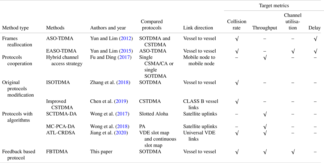
Table 1 shows a comparison of some typical MAC protocols mentioned above. These MAC protocols are summarised and categorised according to method types, compared protocols, link direction and target metrics. The target metrics include collision rate, throughput, channel utilisation and delay. Although these existing methods can reduce collisions to a certain extent, collisions still occur frequently in heavy traffic loads. Furthermore, to the best of the authors’ knowledge, there is no specific standard for the MAC protocol in VDES to address the collision issue. Toward this end, a novel MAC protocol for VDES is proposed, aiming to eliminate transmission collisions. The protocol is listed in the last row of Table 1 for comparison with existing MAC protocols.
Comparison between the different MAC protocols designed for VDES

Notes: symbol ‘√’ means that the metric is presented and analysed in corresponding papers, and symbol ‘–’ means that is not mentioned or specified definitely.
3. VDES architecture and system model
In this section, the architecture of VDES, including VDES components, channel allocation and time slot hierarchy, is presented. Then the model is illustrated to show the scenario of marine communication networks.
3.1 The architecture of VDES
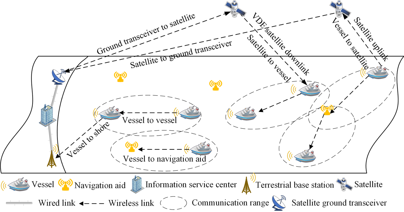
The components of VDES are shown in Figure 1, and it mainly consists of terrestrial base stations, satellite base stations, various vessels and other navigation aids in the network (ITU, 2015; IALA, 2019). Routers exchange data packets through vessels, satellites and shores. Satellite base stations have both uplinks and downlinks, and share several channels with terrestrial base stations, achieving the capabilities of real-time communication and information confirmation backhaul. Such an integrated framework will play a significant role in maritime communication.
Components of VDES

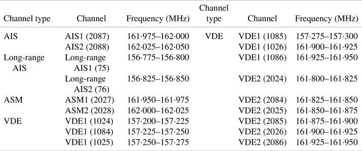
VDES has four types of channels, which consist of 18 channels, i.e., AIS, long-range AIS, ASM and VDE (ITU, 2015). AIS channels have the highest priorities among all types of channels in VDES because AIS channels are used to transmit messages related to navigation safety. Long-range AIS channels are used as uplinks for transmitting AIS messages to satellites. They provide data exchange services outside the terrestrial base stations’ signal coverage or without the terrestrial base stations. Aiming at offloading AIS messages, ASM channels are used to transmit non-navigational messages regulated by the maritime administration. However, ASM channels are not efficiently utilised due to the fact that they are next to the AIS channels thus requiring a stricter spectrum mask (Lázaro et al., Reference Lázaro, Raulefs, Wang, Clazzer and Plass2019). As the core function of VDES, VDE offers channels for vessels to transmit personal messages such as business definition, transmission interface and data model (IALA, 2017). In VDES, all the channels collectively provide services for vessels and the channel allocation is summarised in Table 2 (ITU, 2015).
Channel allocation in VDES

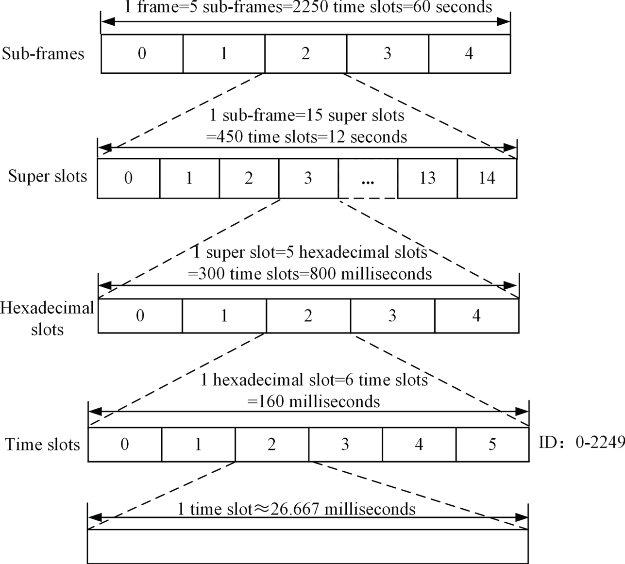
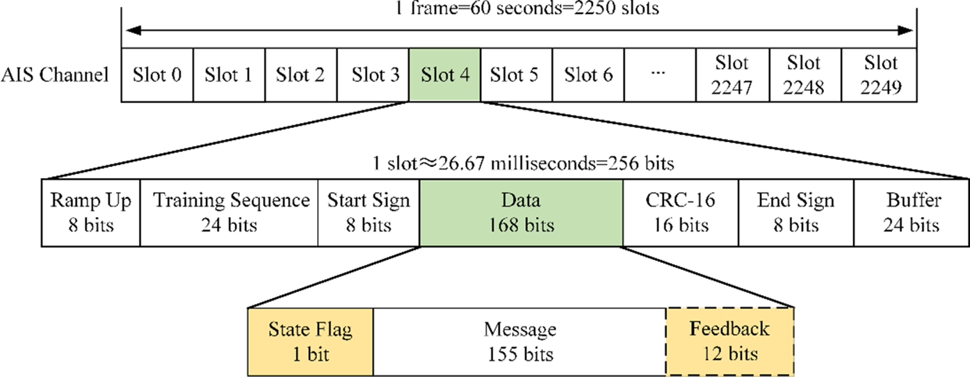
In VDES, time is partitioned into several frames, according to ITU Recommendation M.2092-0. It is recommended that the length of a frame is 60 s and it is divided into four hierarchies, i.e., sub-frames, super slots, hexadecimal slots and time slots, respectively (ITU, 2015), as shown in Figure 2. As we can see, one frame is partitioned into 2,250 time slots, with identities (IDs) from 0 to 2,249. According to the standard, the data rate of the AIS channel is 9⋅6 kbps. Therefore, the time slot length is 26⋅67 ms, and each time slot can accommodate 256 bits.
Time slot hierarchy in VDES

3.2 System model
Consider n vessels in a wireless ad hoc network having IDs from 1 to n, and suppose each vessel always has backlogged traffic to transmit. VDES equipment installed on the vessel covers a large geographical area, fully connected to other vessels in the network. A single AIS channel is available to the network, where every vessel can receive packet transmissions from others. In the network, when a vessel is not sending packets during its reserved slots, it will listen to the channel and detect the transmissions from others. We focus on avoiding transmission collisions that occur when two or more vessels simultaneously initiate a data packet transmission in a specific time slot, and the transmission error of the channel is negligible. Without a controller, vessels exchange local information with each other and remain synchronised in time to coordinated universal time (UTC).
4. The proposed MAC protocol
The SOTDMA protocol widely used in AIS incurs high rates of transmission collision, especially in heavy traffic loads. If a certain slot is occupied for a long time and a collision occurs, the data packet transmitted in this time slot will always be lost, threatening navigation safety. Towards eliminating this collision, the current method used in SOTDMA is the Time Out (TMO) mechanism. To be specific, in SOTDMA, TMO generates a random integer from three to seven for the current reserved time slot and decreases the number gradually as the frames go on. When the integer falls to zero, the vessel stops transmission in the current reserved slot and reserves a new time slot for transmission. Although, in this way, the long-term collision in a specific time slot can be avoided, the TMO mechanism requires frequent new time slot reservation. When the traffic load is heavy, such frequent reservation requests from different vessels may also collide with each other, reducing the channel efficiency.
The core reason for transmission collisions occurring in SOTDMA is the lack of a feedback mechanism. That is, when a collision happens, there is no means in SOTDMA to send feedback to the vessels concerned about such collision. Therefore the collided vessels will keep sending data during the collided slots until time out, resulting in poor channel utilisation. Towards this end, the authors propose the feedback based time division multiple access (FBTDMA) protocol to avoid collisions. The basic idea is that vessels keep listening to the channel and record the state of time slots during the non-transmission time slots. Once a transmission collision is detected, during transmission time slots, the vessels feedback the collision information to the collided vessels by piggybacking the collided time slot IDs on data packet transmissions. Thus the collided vessels can avoid using the collided slot and reserve a new time slot for data transmission. The detailed process of FBTDMA is illustrated as follows.
4.1 Process of FBTDMA protocol
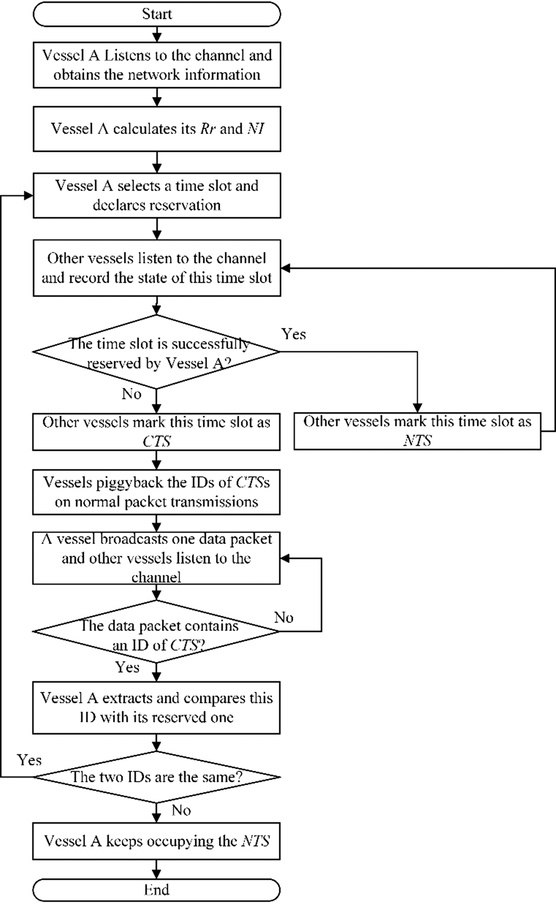
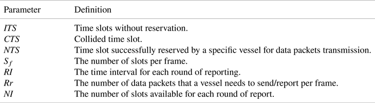
Consider a vessel (named vessel A) that can communicate with other vessels via the FBTDMA protocol. The process of the proposed FBTDMA protocol through vessel A entering the network is described here, as shown in Figure 3. According to the usage, time slots are divided into three categories: idle time slot (ITS), collided time slot (CTS) and nominal transmission slot (NTS). The definitions of the three types of time slots and other symbols are listed in Table 3.
Process of FBTDMA protocol

Important parameters in FBTDMA protocol

When first joining the network, vessel A obtains important network information such as parameters Rr and NI, and ITSs in the network via listening to the AIS channel for one frame (marked as the first frame). According to its motion state, vessel A calculates its Rr and NI by Equations (1) and (2), respectively (ITU, 2014).


In VDES, Sf is usually set at 2,250. Rr reflects the state of vessel A and is related to navigation safety. The larger the Rr, the more necessary data packets vessel A should broadcast. NI indicates the range of time slots available for each reservation by vessel A and it is determined by Rr. The larger NI means that more time slots are available for vessel A to reserve each time, thus there is less possibility for transmission collision.
In the second frame, vessel A accesses the network and reserves NTSs from the ITSs according to Equation (3).

where k indicates the k-th round of report from vessel A during one frame, α is an integer randomly generated from 1 to NI and presents the ID of an ITS selected in each NI. According to Equation (3), the number of NTSs that vessel A needs to reserve is Rr during one frame. During one selected time slot, vessel A sends a data packet to declare the reservation. At the same time, other vessels listen to the channel and record the state of this time slot in their local devices. If the packet sent by vessel A during this NTS can be successfully received by other vessels, it means there is no collision and thus vessel A successfully reserves this NTS. In this case, other vessels mark the state of this NTS as reserved. When another vessel attempts to reserve the same time slot as vessel A, other vessels will detect a collision during that time slot, and then mark that slot as CTS.
After that, in the third frame, the vessels that detect a collision in the second frame are responsible to feedback the collision information to the collided vessels. Specifically, the vessels piggyback the CTS IDs on their normal data packet transmissions. When the NTS comes during the third frame, the vessel broadcasts one data packet (including message and a CTS ID) in the network. Meanwhile, other vessels listen to the channel and record the state of this time slot. After successfully receiving the data packet, vessel A judges whether the data packet contains a CTS ID. If the data packet contains a CTS ID, vessel A extracts and compares the CTS ID with the one that it tried to reserve in the second frame. If the two slots’ IDs are the same, vessel A is aware of an unsuccessful reservation and thus initiates a new reservation. Otherwise, vessel A keeps occupying the reserved NTS until it leaves the network or changes the Rr. Other collided vessels perform in the same way as vessel A. To minimise the overhead introduced by the piggyback mechanism, each vessel feeds back one CTS ID at a time, and vessels take turns to feedback until all the CTSs in the previous frame have been fed back.
4.2 An improved time slot structure for VDES
To feedback all the transmission collisions, the authors propose an improved time slot structure of the AIS channel. As shown in Figure 4, in the improved time slot structure, the original 168-bit data field is further divided into three parts: state flag, message and feedback. The length of the state flag is one bit, and it is used for declaring the purpose of usage of the time slot. When the state flag shows 0, the time slot is used as usual for message transmission through both the message field and the feedback field. In contrast, if the state flag is 1, the time slot is used not only to send messages (through the message field) but also to feedback the information of the CTS IDs in the previous frame (through the feedback field). The message field contains 155 bits which can support various maritime applications. It is noticed that there are 2,250 time slots in a frame, thus it requires 12 bits to represent the slot ID. Therefore, the feedback field contains 12 bits.
Improved time slot structure of the AIS channel for VDES

4.3 An example of feedback procedure
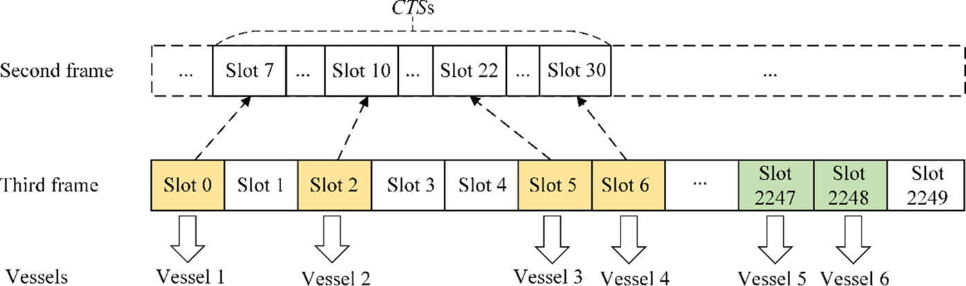
To best explain the feedback procedure, a simple example is used to illustrate it in detail, as shown in Figure 5. After finishing the time slot reservation in the second frame, at Slot 7, Slot 10, Slot 22 and Slot 30, there are two or more vessels trying to reserve the slot, thus causing transmission collisions. We denote these collided time slots as CTSs. Subsequently, vessels detecting collisions record the CTS IDs in their local VDES devices. Six time slots (i.e., Slot 0, Slot 2, Slot 5, Slot 6, Slot 2247 and Slot 2248) were successfully reserved by six vessels (i.e., vessels 1 to 6) respectively. We denote these successfully reserved time slots as NTS. In the third frame, the vessels broadcast data packets in their reserved time slots. Thus, vessel 1 transmits data in Slot 0. Due to the responsibility of feeding back CTS IDs, vessel 1 sets the state flag as 1, packs a message of 155 bits in the message field and a CTS ID (e.g., Slot 7) in the feedback field of its data packet and broadcasts it in Slot 0. Similarly, vessels 2 to 4 will do the same thing, the only difference is that the subsequent vessels need to listen to the transmissions from the previous vessels and choose a CTS ID which has not yet been broadcast to include in its data packet. After vessel 4 completes its transmission, all the CTSs in the second frame have been fed back, thus vessel 5 and vessel 6 can set the state flag as 0, pack a message of 167 bits in both the message and feedback fields, and transmit over their reserved slots.
An example to illustrate the feedback procedure

It is worth noting that the proposed protocol introduces extra overhead due to the addition of the state flag field and the feedback field in the data packet. However, the state flag field has only one bit. Compared with the length of a time slot (i.e., 256 bits), this overhead is very small. Although the feedback field contains 12 bits, vessels only use this field to convey the information of the CTS ID when a reservation collision occurs. Such collisions are expected to be occasional when a network is operating normally (i.e., not extremely overloaded). When there is no collision information to convey, this feedback field will be used to convey normal message information. Therefore, the overhead caused by this feedback field is also small. The simulation results show that the overhead caused by the state flag and feedback fields in our protocol is much smaller than that caused by the TMO mechanism used in the SOTDMA protocol. Thus, the control overhead in the proposed protocol is significantly reduced.
5. The simulation and performance evaluation
This section evaluates the performance of the proposed FBTDMA by extensive simulations. As no representative MAC protocol in VDES is available so far, the proposed protocol is compared with SOTDMA, the widely adopted MAC protocol for AIS. Simulation results are presented to compare the performance of these two protocols in terms of the number of CTSs, collision rate, channel utilisation, and throughput.
5.1 The simulation parameters and performance metrics
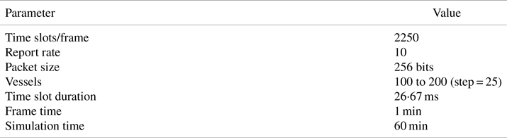
In the simulation, we suppose that all the vessels are randomly distributed in the sea and keep the motion state unchanged. Omnidirectional antennas are used for direct communication in the channel. We assume that the packet can be correctly received by the receiver in a collision-free channel and a packet lost is caused by transmission collision. We consider a worst case that all the vessels access the network and reserve time slots simultaneously at the beginning of the simulation. Unless otherwise mentioned, the main simulation parameters are summarised in Table 4.
Simulation parameters

The following performance metrics are considered:
1. The number of CTSs in each frame.
2. Collision rate: the statistical average number of CTSs per frame during the simulation time.
3. Channel utilisation: the ratio of the time slots used for successful data transmissions to the total time slots during the simulation time.
4. Throughput: successfully transmitted message bits per second.
5.2 Results and performance analysis
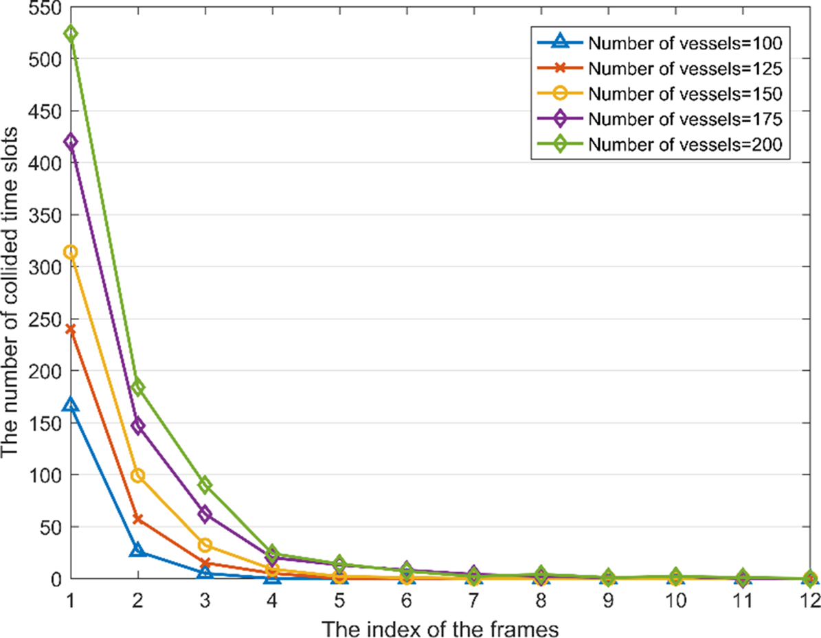
Figure 6 shows the number of CTSs versus the index of the frames in the FBTDMA protocol with a different number of vessel settings. It can be seen that the proposed protocol achieves collision-free communications gradually within several frames. The number of CTSs in the first frame is relatively high compared with that in subsequent frames. For instance, this number reaches 524 in the first frame when the number of vessels is 200. Then, it decreases from the peak in the first frame to zero as the frames increase. The maximum number is in the first frame due to the fact that all the vessels start to reserve slots in the first frame. This result indicates that our protocol effectively eliminates collisions, thereby ensuring that the data packets are transmitted successfully.
The number of collided time slots in FBTDMA protocol versus the index of the frames

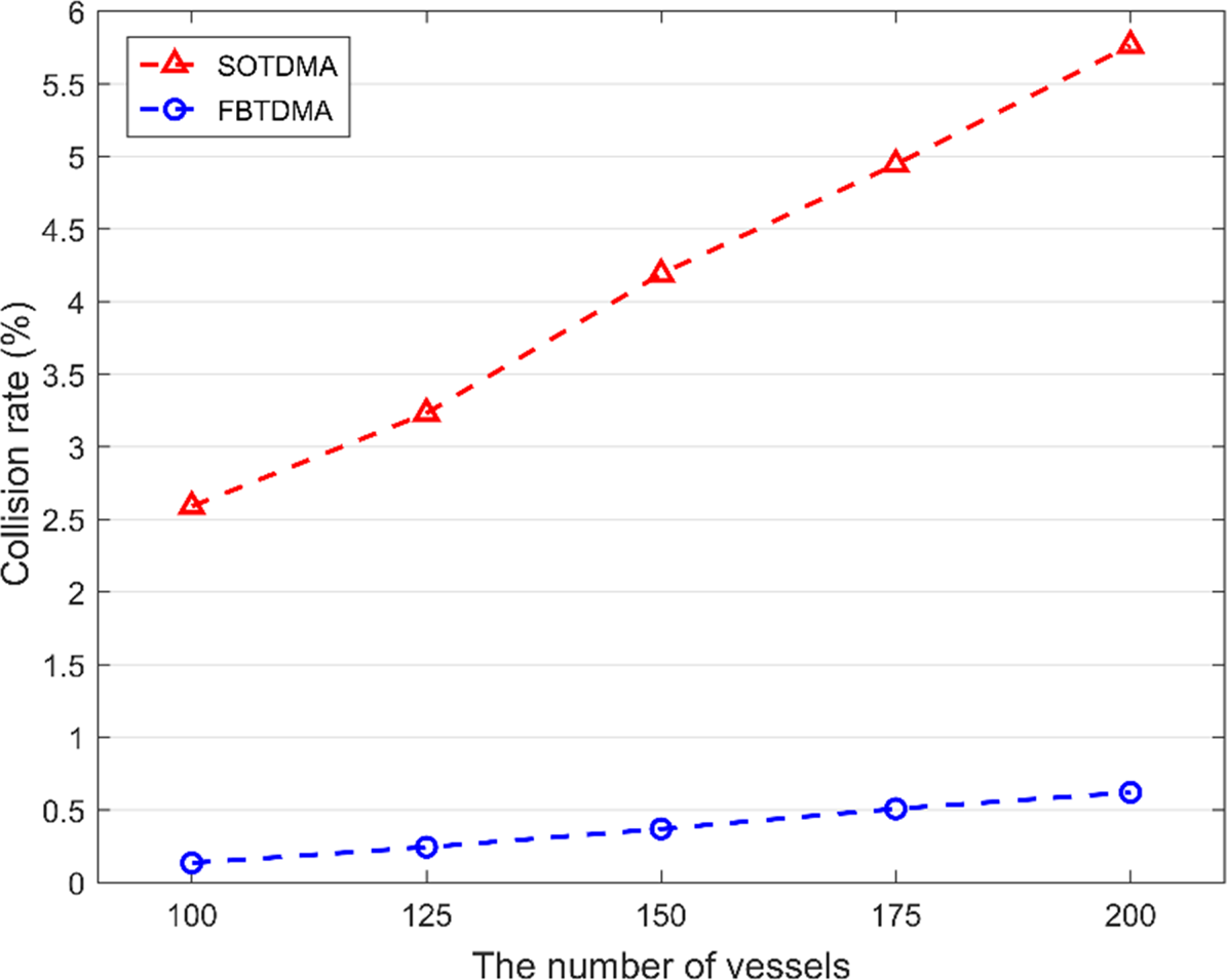
Next, in Figure 7, the collision rate of SOTDMA is compare with the proposed protocol. As expected, the collision rate in FBTDMA is much less than that in SOTDMA. For instance, when the number of vessels is 150, the collision rate in SOTDMA reaches 4⋅55%, whereas it is only 0⋅36% in FBTDMA. The result implies that the FBTDMA protocol eliminates more transmission collisions than SOTDMA. Moreover, the collision rate increases with the number of vessels for both protocols. As we can see, for SOTDMA, the collision rate increases from 3⋅04% to 6⋅23% as the vessel numbers increase from 100 to 200. For comparison, the collision rate of FBTDMA only rises from 0⋅13% to 0⋅60%. This result indicates that the proposed protocol effectively and significantly reduces the collisions.
Collision rates of SOTDMA and FBTDMA with 100–200 vessels

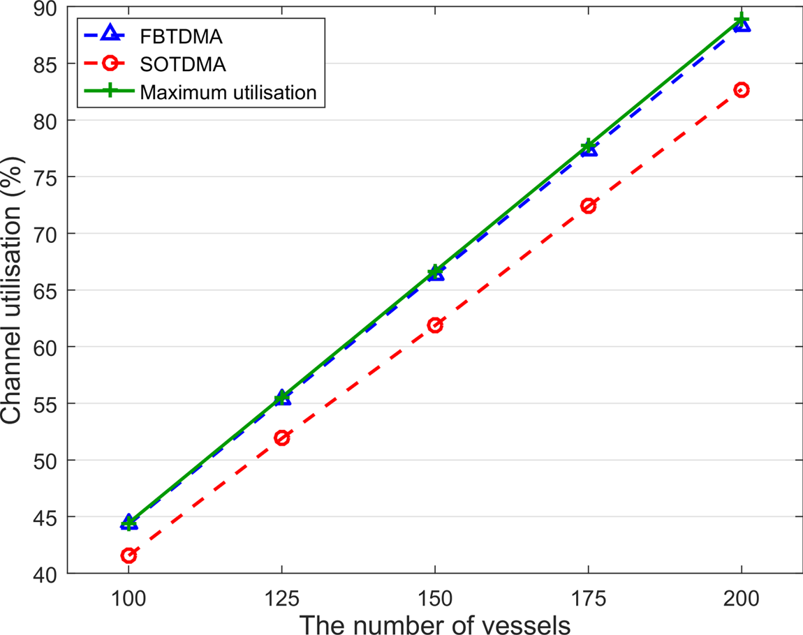
In Figure 8, the channel utilisation of SOTDMA is compared with FBTDMA. The channel utilisation increases in both protocols as the number of vessels increases. The channel utilisation in FBTDMA is higher than that of SOTDMA and close to the utilisation of the collision-free channel, named the maximum utilisation. For instance, when the number of vessels is 150, the rates of channel utilisation in SOTDMA and FBTDMA are 61⋅87% and 66⋅29%, respectively. The latter approaches the maximum utilisation rate, 66⋅67%. This result confirms that the proposed protocol provides a higher channel utilisation compared with SOTDMA.
Channel utilisation of SOTDMA and FBTDMA

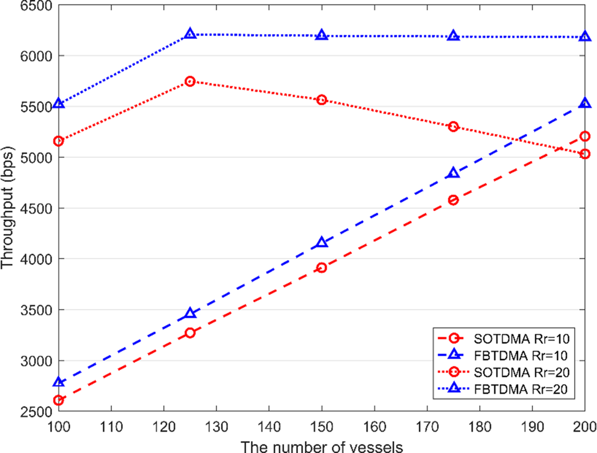
To investigate the throughput performance of the two protocols under heavy traffic, Figure 9 compares the throughput of FBTDMA with SOTDMA in two cases: Rr equal to 10 and 20, respectively. We can see that the throughput in FBTDMA is much higher than that in SOTDMA during the simulation time. For instance, when the Rr is 10 and the number of vessels is 150, the throughput in FBTDMA is 4,152 bps, whereas that in SOTDMA is 3,912 bps. When Rr is 20, the throughput of SOTDMA first increases as the number of vessels increases. When the number of vessels is 125, the throughput reaches the maximum and then gradually decreases as the number of vessels further increases. The reason is that when the data traffic grows to exceed the capacity of the channel, SOTDMA suffers higher transmission collisions, resulting in a lower throughput. However, the throughput in the proposed protocol becomes stable at maximum value after the data traffic exceeds the capacity of the channel. Therefore, the proposed protocol outperforms SOTDMA in terms of throughput.
Throughput of SOTDMA and FBTDMA with different Rr

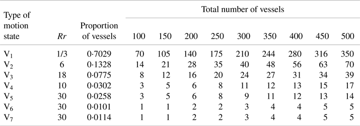
In the previous simulations, for simplicity it was assumed that all the vessels have the same Rr. Considering vessels’ Rr may be different in the actual environment, further study considered seven types of vessels with different Rr and proportions for the FBTDMA performance evaluation. The types of vessels, V1 to V7, are defined according to factors such as sailing speed (Zhang et al., Reference Zhang, Lin, Zhang, Zhao and Zhang2018). Moreover, the proportion of each type is given to calculate the number of vessels. In this scenario, the total number of vessels is set from 100 to 500 with the step of 50 and detailed illustrations are shown in Table 5.
The vessel proportion settings in different types of motion states

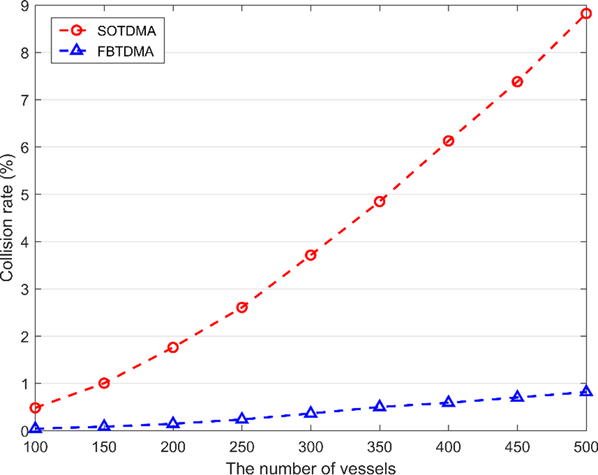
Figure 10 shows the collision rate of SOTDMA and FBTDMA in this scenario. When the number of vessels varies from 100 to 500, the collision rate in both protocols increases. In SOTDMA, the collision rate grows sharply from 0⋅48% to 8⋅82%. However, in the FBTDMA, the rate rises from 0⋅04% to 0⋅82%. As we can see, the growth of FBTDMA is 0⋅78%, which is much lower than that of 8⋅34% in SOTDMA. Such a result indicates that the FBTDMA protocol can effectively reduce the collision rate and efficiently transmit data packets.
Collision rates of SOTDMA and FBTDMA with 100–500 vessels

6. Conclusions
At present, AIS has suffered from transmission collisions in heavy traffic loads due to the traditional SOTDMA protocol employed in the network. It is necessary and urgent to build a novel MAC for next-generation maritime communication systems. This paper has proposed the FBTDMA protocol for VDES to support E-navigation modernisation and general maritime communications. A modified data packet structure is adopted in FBTDMA to feedback collision information among vessels. Simulations have been conducted to verify the performance of the proposed FBTDMA. The results have demonstrated that the proposed protocol effectively improves channel utilisation and throughput, and significantly reduces the collision rate compared with SOTDMA.
In this paper, it is assumed that data can be successfully transmitted by vessels in the non-collision case. However, there still exists packet loss in practice due to the impairments of physical layer channels even in the non-collision case, which may cause false alarm of collision detection in the MAC protocol. For further study, the authors will consider a more practical scenario where the path loss and interference of the channel may cause transmission errors. This study is expected to provide helpful insights into the development of the MAC protocol standard in VDES under the concept of E-navigation.
Acknowledgements
The work was supported by the National Key Research and Development Programme of China (Grant No. 2019YFE0111600), National Natural Science Foundation of China (Grant Nos. 61971083, 51939001 and 61976033), Dalian Science and Technology Innovation Fund (Grant Nos. 2019J11CY015 and 2018J11CY022), and the Liaoning Revitalisation Talents Programme (Grant Nos. XLYC1908018 and XLYC1807046).