
Bioinspiration, biomimetics, and bioreplication
Biologic species are endowed with multiscale structures ranging from the nano- to micro- to macroscales, which provide them with very specific functionalities. The objective of bioinspiration is to reproduce the outcome of a particular functionality of a given species, but the biologic structure responsible for the outcome is not reproduced. The objective of biomimetics is to imitate the particular mechanism behind a specific functionality of a living organism. Going one step further, bioreplication is the replication of a specific biologic structure to reproduce a particular functionality of that structure. These three methodologies of “engineered biomimicry” are highly multidisciplinary.[Reference Bar-Cohen1–Reference Lakhtakia and Martín-Palma3] The broad field of engineered biomimicry is represented in current research in many fields, including such disciplines as solar-energy harvesting,[Reference Martín-Palma and Lakhtakia4] locomotion,[Reference Vepa5–Reference Marras and Porfiri7] and surface science.[Reference Amador and Hu8–Reference Domel, Saadat, Weaver, Haj-Hariri, Bertold and Lauder10]
The scope of bioreplication is vast for the design and manufacture of devices as this methodology aims to reproduce spatial features of biologic structures. However, as the formation processes of biologic structures are very complex, the discovery of pathways for exact imitation of natural processes is generally infeasible on human time scales. In some instances, a simple alternative is to fabricate the replicas of a biologic surface by means of a high-fidelity templating technique that is capable of accurate replication of features at very different length scales. This approach could underlie an industrially scalable process for the inexpensive fabrication of surface structures with the desired functionalities. Indeed, then long-lasting bioreplicas could be made of environmentally stable materials.[Reference Huang, Wang and Wang11]
We discuss, in the following sections, the fundamentals and some key applications of a new technique that emerged from physical vapor deposition of planar thin films for “traditional” optical applications[Reference Hodgkinson and Wu12–Reference Lakhtakia and Messier14] and has been used for industrially scalable replication of biosurfaces,[Reference Pulsifer, Lakhtakia, Martín-Palma and Pantano15, Reference Pulsifer, Lakhtakia, Narkhede, Domingue, Post, Kumar, Martín-Palma and Baker16] forensic identification of human fingerprints,[Reference Lakhtakia, Shaler, Martín-Palma, Motyka and Pulsifer17–Reference Muhlberger, Pulsifer, Lakhtakia, Martín-Palma and Shaler19] and archival storage of images of complex multiscale surfaces.[Reference Abeywickrema, Banerjee, Kota, Swiontek and Lakhtakia20]
From oblique-angle deposition (OAD) to the conformal-evaporated-film-by-rotation (CEFR) technique
The OAD technique has been used for more than 125 years[Reference Mattox21] to fabricate thin films comprising parallel columns. The diameter of the columns is on the nanoscale for optical applications,[Reference Hodgkinson and Wu12–Reference Lakhtakia and Messier14] but it can be enhanced to the microscale for electronic applications,[Reference Khawaji, Chindam, Awadelkarim and Lakhtakia22, Reference Khawaji, Chindam, Awadelkarim and Lakhtakia23] phononic applications,[Reference Chindam, Lakhtakia and Awadelkarim24] and biomedical applications.[Reference Wei, Lakhtakia, Roopnariane and Ritty25, Reference Wei, Vogler, Ritty and Lakhtakia26] The films are commonly called columnar thin films (CTFs).
The OAD technique is implemented in a low-pressure chamber. Material in a crucible is evaporated by resistive heating, electron-beam bombardment, irradiation by laser pulses, or bombardment by a beam of heavy ions and/or atoms.[Reference Hodgkinson and Wu12, Reference Lakhtakia and Messier14, Reference Martín-Palma and Lakhtakia27] A highly collimated portion of evaporant flux is directed toward a stationary substrate at an angle χ v (0° < χ v ≤ 90°) with respect to the plane of a platform to which the substrate is affixed. Due to shadowing effects, the arriving adatoms are preferentially deposited on top of the surface features with larger heights.[Reference Messier, Venugopal and Sunal28] An assembly of parallel tilted columns grows on top of the substrate as a result.[Reference Mattox21] The cross-sectional dimensions of the columns depend on the deposition conditions as well as the chemical composition of the evaporant flux.
A CTF is electromagnetically equivalent to a biaxial crystal at free-space wavelengths more than an order of magnitude larger than the typical linear cross-sectional dimensions of the columns.[Reference Gribble and Hall29] In addition to χ v, the three principal refractive indices of the CTF depend on the deposition parameters and the material.[Reference Hodgkinson and Wu12]
The columnar morphology of a growing film can be engineered by a dynamic change of the direction of the evaporant flux. This is the principle underlying the conceptualization of sculptured thin films (STFs).[Reference Wei and Lakhtakia30] STFs are assemblies of parallel columns of almost identical shapes and are grown by proper control of substrate motion with respect to fixed axes.[Reference Lakhtakia and Messier14, Reference Wei and Lakhtakia30]
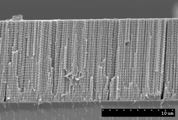
Figure 1 shows the cross-sectional scanning-electron micrograph of a chiral STF. During its fabrication using the OAD technique, the substrate was rotated about an axis passing normally through the center of the substrate plane. All of its columns are helicoidal in shape. As a result of its structural chirality, the chiral STF distinguishes between incident left- and right-circularly polarized light. The evaporated material and the helicoidal pitch (~367 nm) were selected so that this chiral STF functions as a circular-polarization filter in the near-infrared spectral regime. Similar filters have also been made for the short-wavelength infrared regime[Reference Pulsifer, Martín-Palma, Swiontek, Pantano and Lakhtakia31] and, very recently, for the mid-wavelength infrared regime.
Cross-sectional scanning-electron microscope image of a zinc–selenide STF designed to operate as a circular-polarization filter in the near-infrared spectral regime.

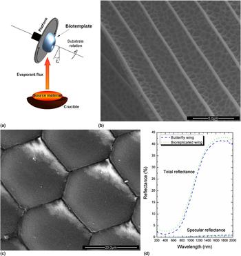
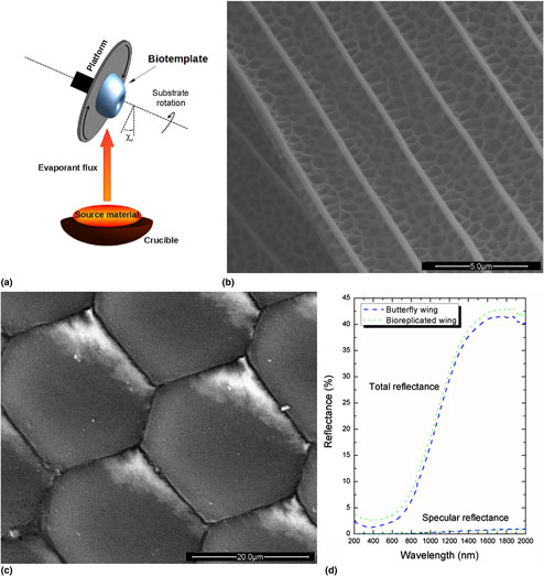
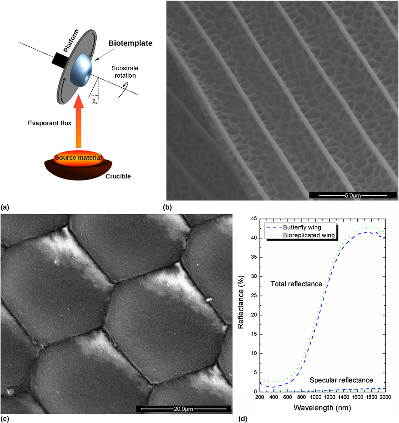
The CEFR technique evolved from the OAD technique. OAD is combined with rapid substrate rotation (typically between 30 and 120 rpm) about the central normal axis in the CEFR technique, as depicted in Fig. 2(a). Furthermore, χ v is fixed at about 5°. The substrate is of biologic origin. Once the deposition process is complete, the deposited film can be separated from the biotemplate, provided that the film is thick enough (typically ~500 nm for nickel). The separated film is a self-supporting high-fidelity replica of the biotemplate. This technique has been successfully used for the fabrication of high-fidelity replicas (at the nanoscale) of biotemplates of several different types. These include corneas of the compound eyes and other parts of flies,[Reference Martín-Palma, Pantano and Lakhtakia32] butterfly wings,[Reference Martín-Palma, Pantano and Lakhtakia33, Reference Lakhtakia, Martín-Palma, Motyka and Pantano34] and beetle exoskeletons,[Reference Pulsifer, Lakhtakia, Narkhede, Domingue, Post, Kumar, Martín-Palma and Baker16, Reference Gupta, Swiontek and Lakhtakia35] as discussed in “Evolution of the CEFR technique” section, as well as microelectronic circuitry.[Reference Martín-Palma, Pantano and Lakhtakia36] Thus, the CEFR technique can replicate complex multiscale features of both planar and non-planar surfaces.
(a) Schematic representation of the CEFR technique. (b) Scanning-electron microscope image of a wing of the butterfly Battus philenor coated with a ~500 nm-thick Ge28Sb12Ge60 film using the CEFR technique. (c) Scanning-electron microscope image of a compound eye of a hornet coated with a ~400 nm-thick silver film using the CEFR technique. (d) Reflectance spectra of a butterfly wing before and after conformal coating by a ~500 nm-thick Ge28Sb12Ge60 film.
Evolution of the CEFR technique
Evolutionary processes have ensured that biologic species possess diverse structures with very specific optical performance to simultaneously fulfill such requirements as either high or low reflectance in a particular spectral regime, or to diffuse incident light in a wide angular sector. These specific optical functionalities serve in camouflage, territorial assertion, and courtship, all of which can be responsible for the enhancement of reproductive success. Insects provide many examples of optical micro- and nanostructures to enable iridescence and/or to appear metallic.[Reference Parker and Townley37–Reference Dushkina, Lakhtakia, Lakhtakia and Martín-Palma39]
With this observation in view, initial research on the CEFR technique for bioreplication was centered on the reproduction of the surface morphology and, therefore, the characteristic reflection characteristics of exoskeletal structures of various insects. Figure 2(b) shows the top view of a wing of a butterfly coated with a ~500 nm-thick film of Ge28Sb12Ge60 chalcogenide glass, whereas Fig. 2(c) shows the top view of a compound eye of a hornet coated with a ~400 nm-thick film of silver.
The specular and the total reflectance spectra of the butterfly wing before and after being coated were measured in the ultraviolet, visible, and infrared spectral regimes (200–2000 nm wavelength), as shown in Fig. 2(d). When compared with the uncoated wing, it is observed that the coated wing is somewhat “chemically colored” as the refractive index of Ge28Sb12Ge60 chalcogenide glass is larger than that of wing material. Minor additional variations can have their origin in wavelength-dependent absorption in the chalcogenide glass.
Anyhow, the similar reflectance characteristics of the uncoated and coated wings confirm that use of the CEFR technique resulted in faithful replication of the surface morphology of the biotemplate. Indeed, disturbance of the surface morphology and/or significant thickness variations of the ~500 nm-thick film of Ge28Sb12Ge60 would have led to notable color changes due to thickness gradient, interference, and diffraction.
In all, the experimental results show that the original biotemplate was not distorted by the implementation of the CEFR technique. Moreover, the CEFR technique did not create a new structure that would alter optical characteristics.[Reference Martín-Palma, Pantano and Lakhtakia32–Reference Lakhtakia, Martín-Palma, Motyka and Pantano34] In fact, we conclude that those characteristics of the biotemplate, originating from nanoscale structural features, were not compromised and that the deposited CTF was a conformal coating.
Accordingly, the CEFR technique allows an efficient and high-fidelity replication of the complex surface features of biotemplates, with a deposition rate approaching several nm s−1. This technique is very well suited for bioreplication, given that the biotemplate is not damaged during the deposition process, the main reason being that deposition occurs at temperatures below around 50 °C in a non-corrosive environment.
Many biotemplates have thickness variations due to lenticularity. To improve thickness uniformity over large-area biotemplates, an additional degree of freedom to substrate motion was introduced in the CEFR technique.[Reference Pulsifer, Lakhtakia and Martín-Palma40] The second degree of freedom is the rocking of the biotemplate about an axis that is tangential to the planar platform on which the biotemplate is affixed during deposition. Accordingly, during deposition, there is either a continuous or an episodic variation of the angle χ v. The effectiveness of this modification of the CEFR technique was first demonstrated by conformally coating the cornea of the compound eye of a common blowfly (Eucalliphora lilea).[Reference Pulsifer, Lakhtakia and Martín-Palma40]
In a later development to conformally coat the wings of the monarch butterfly (Danaus plexippus) with nickel, a further modification of the CEFR technique was introduced.[Reference Tolenis, Swiontek and Lakhtakia41] A 250 nm-thick film was deposited with χ v = 7° first, followed by another 250 nm-thick film with χ v = 20°. This modification ensured the deposition of nickel into the overhangs of the wings and produced a sturdier coating that still captured the morphology of the wing very well.
Forensic applications
Fingerprints are biotemplates completely different from the eyes of insects and wings of butterflies. Comprising water, saturated fats, waxes, squalene, urea, amino acids, and salts,[Reference Robinson and Robinson42] a typical fingerprint's topology has features ranging from the micrometer scale to the millimeter scale. Many fingerprints left at crime scenes are classified as latent, i.e., their features are not visually accessible for forensic examination without physical and/or chemical processing.[Reference Cole43] But a fingerprint left on a specific forensically relevant surface requires a specific type of development, if it can be seen well enough for forensic identification.
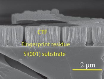
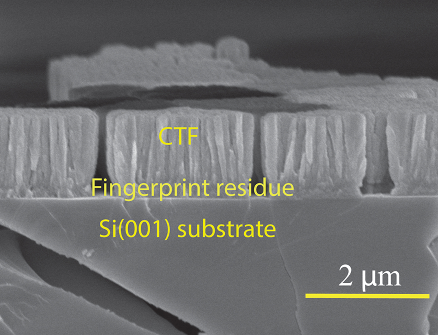
Deposition of conformal CTFs on latent fingerprints on diverse non-porous surfaces using the CEFR technique has turned out to be a rather versatile way of development for visualization.[Reference Lakhtakia, Shaler, Martín-Palma, Motyka and Pulsifer17–Reference Muhlberger, Pulsifer, Lakhtakia, Martín-Palma and Shaler19] As an example, Fig. 3 shows a ~1500 nm-thick CTF of Ge28Sb12Ge60 chalcogenide glass deposited conformally on top of a ~200 nm-thick portion of a fingerprint laid on a microscope glass slide.[Reference Swiontek, Pulsifer and Lakhtakia44] Not only does the CEFR technique work well enough to identify 120 µm-diameter and 2000 nm-deep pores in the ridges of latent partial fingerprints,[Reference Abeywickrema, Banerjee, Kota, Swiontek and Lakhtakia20, Reference Swiontek, Pulsifer and Lakhtakia44] but it can be also used for a single-step development of even a partial bloody fingerprint[Reference Williams, Pulsifer, Lakhtakia and Shaler45] that is typically difficult to process because one part has blood proteins that can interfere with the development of the other (i.e., latent) part.
Cross-sectional scanning-electron microscope image showing of a ~1500 nm-thick CTF of Ge28Sb12Ge60 deposited on a latent sebaceous fingerprint laid on a microscope glass slide.
Digital holographic acquisition, storage, and analysis of three-dimensional (3D) images of latent fingerprints developed using the CEFR technique have been shown possible.[Reference Abeywickrema, Banerjee, Kota, Swiontek and Lakhtakia20] Fine details, such as the pores in the ridges, are captured by the digital holograms and shall be available for analysis even after a fingerprint has been destroyed in a subsequent assay for identification.
Often but not always, a fingerprint contains as many as three cells that can be used for identification using DNA analysis.[Reference Balogh, Burger, Bender, Schneider and Alt46] The conformal CTF entombs the fingerprint thereby protecting those cells. More importantly, the CTF does not inhibit DNA analysis.[Reference Plazibat, Roy, Swiontek and Lakhtakia47] A forensic examination of a CTF-visualized partial fingerprint followed by DNA analysis of the entombed cells will yield doubly sure identification of actors at crime scenes.
Mass replication of biotemplates
Based on the CEFR technique, the Nano4Bio technique was developed for the high-fidelity replication of biotemplates.[Reference Pulsifer, Lakhtakia, Martín-Palma and Pantano15] The underlying objective was to enable the mass production of inexpensive bioreplicas.
The crux of the Nano4Bio technique is the production of a master negative from the biotemplate for subsequent use as either a die for stamping or a mold for casting. In the first step of the Nano4Bio technique, the biotemplate is conformally coated with a thin layer (typically between 250 and 500 nm) of nickel, using either the CEFR technique or one of its modifications. Next, electroforming is used to grow a thick nickel coating (typically, ~60 µm thick). This thick coating provides the master negative with the mechanical robustness required for casting or stamping numerous times. The biotemplate is separated from the nickel coating in the third step. For this purpose, either chemical methods or plasma ashing can be used. This process results in a master negative, which can be subsequently used for the fabrication of multiple replicas.
The fourth step of the Nano4Bio technique, namely casting, results in high-fidelity reproduction, at least at the 200 nm length scale.[Reference Pulsifer, Lakhtakia, Martín-Palma and Pantano15] The resolution is likely to be much better since nickel nanograins are about 20 nm in diameter. The master negative can also be used as a die for stamping in lieu of casting.[Reference Pulsifer, Lakhtakia, Narkhede, Domingue, Post, Kumar, Martín-Palma and Baker16, Reference Gupta, Swiontek and Lakhtakia35]
Visual decoys for pest control
The Nano4Bio technique was effectively used to fabricate visual decoys to lure Agrilus biguttatus [Reference Pulsifer, Lakhtakia, Narkhede, Domingue, Post, Kumar, Martín-Palma and Baker16] and Agrilus planipennis,[Reference Domingue, Lakhtakia, Pulsifer, Hall, Badding, Bischof, Martín-Palma, Imrei, Janik, Mastro, Hazen and Baker48] both being buprestid species of insects. The latter species is called the emerald ash borer (EAB) and is a highly invasive pest in North America.
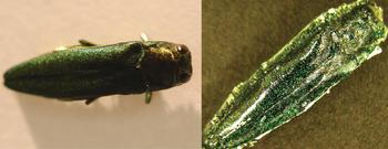
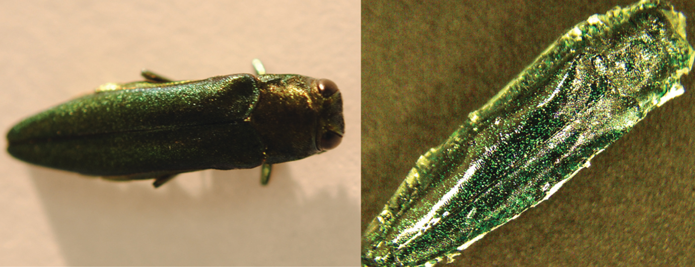
In order to prepare the decoys, a poly(ethylene terephthalate) (PET) sheet was stamped with two dies bioreplicated from a dead EAB female. The PET sheet was coated before the replication step with a periodic bilayer of two different polymers in order to engender a structural color[Reference Dushkina, Lakhtakia, Lakhtakia and Martín-Palma39] close to that of the elytra of the EAB. It is worth pointing out that around a hundred decoys were fabricated from a single biotemplate, demonstrating that the Nano4Bio technique is industrially scalable. The results of field testing of the decoys showed them to be significantly more effective than dead EAB females[Reference Pulsifer, Lakhtakia, Narkhede, Domingue, Post, Kumar, Martín-Palma and Baker16, Reference Domingue, Lakhtakia, Pulsifer, Hall, Badding, Bischof, Martín-Palma, Imrei, Janik, Mastro, Hazen and Baker48] as well as 3D-printed decoys[Reference Domingue, Pulsifer, Lakhtakia, Berkebile, Steiner, Lelito, Hall and Baker49] for attracting overflying beetles. Nano4Bio decoys that were spray painted instead of being structurally colored turned to be efficacious as well, leading to a simpler technique[Reference Gupta, Swiontek and Lakhtakia35] for replicating the decoys from a master negative. Figure 4 shows a dead A. planipennis female along with a visual decoy.
Dead Agrilus planipennis female (left). Visual decoy produced using a simpler variant of the original Nano4Bio technique (right).
Light emission with improved angular spread
A large number of simple eyes are arranged like florets in a cauliflower head to form a compound eye in insects of many species. This arrangement provides them a wide angular field of view,[Reference Horridge50] making these natural optical structures attractive for the development of bioreplicated sources of light.
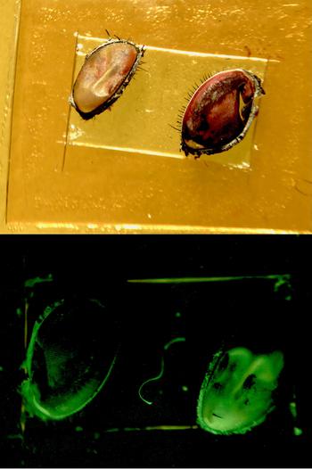
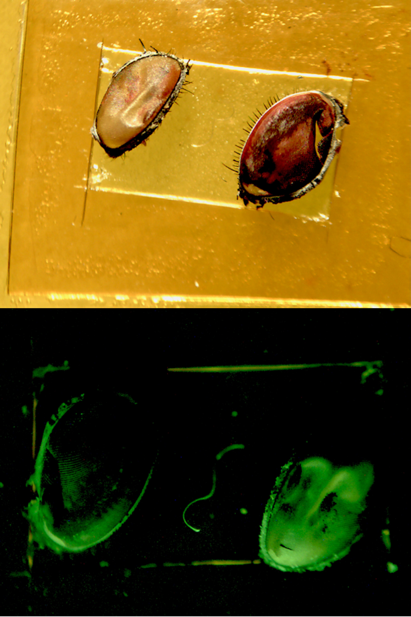
Therefore, corneas of compound eyes of the common blowfly (E. lilea) were conformally coated with Alq3, as shown in Fig. 5, and illuminated with ultraviolet light. The angular distribution of green light emitted by a coated cornea was compared with that emitted by a flat surface of the comparable cross-sectional area.[Reference Martín-Palma, Miller, Pulsifer and Lakhtakia51] The experimental results showed that the conformally coated cornea has a notable weaker angular dependence of emission than the flat surface. This initial demonstration should impact the development of bioreplicated light-emitting and light-detecting devices.
Photographs of blowfly corneas mounted on a glass slide before (top, taken under normal illumination) and after (bottom, taken under shortwave-ultraviolet illumination) being coated with Alq3.
Concluding remarks
In many cases, a specific functionality of a biologic structure emerges from its morphology at the nanometer, micrometer, and/or macroscopic length scales. This diversity of length scales makes the selection of an adequate bioreplication technique a crucial issue, particularly because the selection also depends on other characteristics of the chosen biotemplate. Within this context, the OAD technique for depositing CTFs evolved into the CEFR technique to replicate the surface features of biotemplates for optical applications. The replication technique requires the deposition of a conformal CTF on the exposed surface of a biotemplate. Variations of the CEFR technique were devised to reduce the spatial variability of the conformal CTF.
The CEFR technique was cascaded with three industrially commonplace processes––namely, electroforming, plasma ashing, and stamping/casting––resulting in the Nano4Bio technique. This bioreplication technique can be effectively used for the mass production of bioreplicas in order to replicate a given functionality of a specific biotemplate, provided that the desired functionality arises from topology at the nanometer, micrometer, and/or macroscopic length scales. Through optical applications for forensic science, pest control, and light sources, the capability of the Nano4Bio technique for replicating surface features over a broad range of length scales has been demonstrated.
Acknowledgments
Both authors are grateful to Vikas Vepachedu (Penn State) and Stephen E. Swiontek (Penn State) for assistance with some figures. AL thanks the Charles Godfrey Binder Endowment for continued support of his research at Penn State.