Nomenclature
- UAV
-
unmanned aerial vehicle
- EMS
-
energy management system
- PV
-
photovoltaic
- Li-Po
-
lithium-polymer
1.0 Introduction
Unmanned aerial vehicles (UAVs) are becoming essential tools for a variety of civil and scientific applications, such as precision agriculture, infrastructure inspections, environmental monitoring and disaster response [Reference Colomina and Molina1–Reference Valavanis and Vachtsevanos3]. Their ability to operate autonomously and their flexibility make them highly effective in hazardous, remote or otherwise inaccessible environments where manned systems would be impractical or unsafe. However, despite these advantages, the limited flight endurance due to restricted onboard energy storage continues to be a significant challenge, preventing more widespread and sustained use of UAVs [Reference Mohsan, Othman, Li, Alsharif and Khan4, Reference Jiao, Zhang, Zhou and Li5].
Modern UAVs primarily rely on lithium-ion (Li-ion) or lithium-polymer (Li-Po) batteries, chosen for their high power-to-weight ratio, quick discharge capabilities and ease of operation. Despite these advantages, their limited energy density typically restricts flight times to around 25–40 min for small- to medium-sized UAVs, limiting the scope and persistence of missions [Reference Jiao, Zhang, Zhou and Li5, Reference Anoune, El Maliki and Belkasmi6]. While alternative energy sources, such as hydrogen fuel cells, offer higher specific energy and have been explored for long-endurance UAV applications [Reference Bradley, Moffitt, Mavris and Parekh7, Reference Elkerdany, Safwat, Yossef and Elkhatib8], they come with complications, including system complexity, additional weight, safety issues and the need for specialised refueling infrastructure, which have hindered their practical deployment. Simultaneously, advancements in photovoltaic (PV) technology and the development of lightweight, flexible solar modules have made it possible to integrate solar panels into UAV designs, enabling in-flight energy harvesting during daylight operations [Reference Stern, Steele, Yang and Kruse9–Reference Bibbò, Laganà, Bilotta, Meduri, Angiulli and Cotroneo11]. Despite this, UAVs powered solely by solar energy remain unreliable due to sensitivity to fluctuating irradiance, shading, weather changes and daily cycles, making them unsuitable as stand-alone power sources in real-world conditions [Reference Bibbò, Laganà, Bilotta, Meduri, Angiulli and Cotroneo11, Reference Hu, Guo, Zhou and Li12].
To address these challenges, hybrid energy systems that combine photovoltaic arrays with battery storage are becoming increasingly popular in both academic research and practical UAV development [Reference Frigioescu, Badea, Dombrovschi and Căldărar13, Reference Engin, Çınar and Kandemir14]. In these systems, solar energy helps to supplement the propulsion load when conditions are favourable, while the battery acts as an energy reserve during periods of low solar irradiance or when the propulsion load fluctuates. The overall performance of hybrid UAV power systems is, however, highly dependent on the energy management strategy (EMS) applied. Conventional rule-based EMS methods are typically computationally efficient and easy to interpret but may struggle to adapt to the rapidly changing dynamics of flight and environmental variability [Reference Engin, Çınar and Kandemir14, Reference Bakar, Ke, Liu, Xu and Wen15]. Optimisation methods, such as particle swarm optimisation (PSO) and genetic algorithms, can improve power distribution, but these approaches often require significant computational resources, making them less suitable for real-time deployment on embedded UAV control systems [Reference Gao, Qiao, Pei, Wu and Bai16, Reference Yavuz and Kivanç17]. More recent studies have investigated closed-loop EMS frameworks, multi-objective optimisation and predictive energy forecasting using machine learning; however, there is limited research that integrates these techniques into a unified, computationally efficient and interpretable framework specifically designed for small- to medium-scale UAV platforms [Reference Hu, Guo, Zhou and Li12, Reference Sehrawat, Vashisht, Singh, Dhiman, Viriyasitavat and Alghamdi18, Reference Bayrak and Kaya19].
This paper presents a novel hybrid EMS tailored for small- to medium-sized UAVs. The proposed system integrates: (i) a real-time fuzzy logic decision layer for power management, (ii) a short-term solar irradiance prediction module based on machine learning algorithms and (iii) a closed-loop proportional-integral-derivative (PID) motor control system to maintain propulsion stability. The framework is designed to enable coordinated, predictive power sharing between the photovoltaic subsystem and the Li-Po battery while ensuring computational feasibility for embedded UAV flight controllers. The focus is on interpretability, structured decision-making and robustness under varying irradiance and load conditions. Simulation results, assuming a constant 320 W propulsion load and a 148 Wh Li-Po battery, show that the battery-only configuration provides an endurance of approximately 28 min. With the integration of an 80 W effective PV input, flight endurance increases to about 37 min, while a 160 W effective PV input extends the flight time beyond 50 min and enables a 45-min mission with more than 20% of the battery’s state of charge (SOC) remaining. This represents an endurance improvement of up to 79% compared to the battery-only configuration, along with a significant reduction in the net battery discharge rate. These results highlight the potential of hybrid energy management in enhancing the resilience and efficiency of UAV missions. Future research will include hardware-in-the-loop testing and real-world flight trials to evaluate system performance under realistic solar variability and environmental conditions.
2.0 Prolonged flight with UAV hybrid energy management
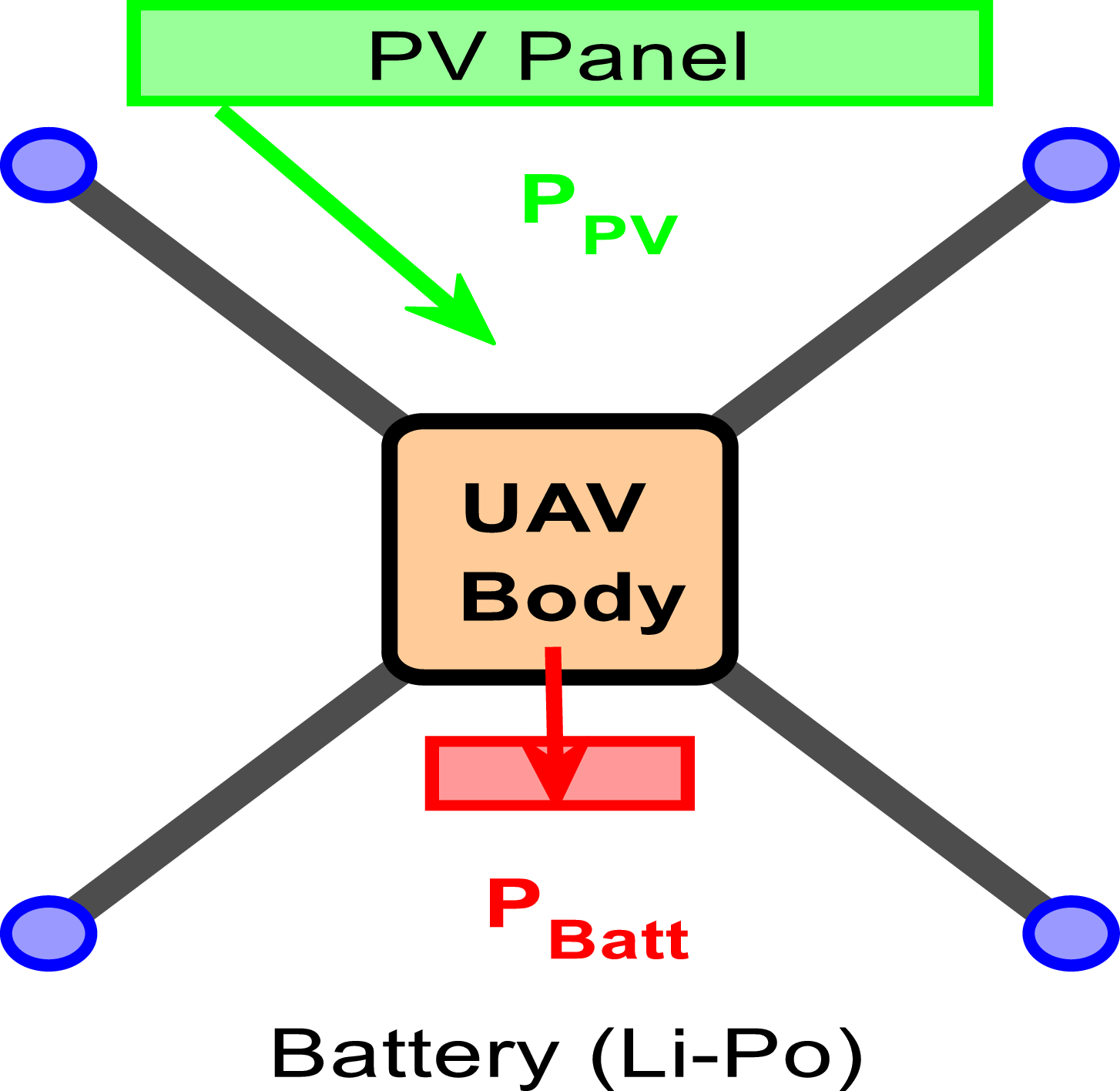
Figure 1 illustrates the schematic configuration of a quadcopter-type UAV equipped with a hybrid EMS designed to optimise flight endurance under variable solar irradiance. The UAV features four electrically driven rotors at the end of each arm, enabling stable vertical takeoff, landing and controlled manoeuvring.
The schematic layout of a quadcopter-type UAV integrated with a hybrid EMS.

The central power subsystem consists of a Li-Po battery with a nominal energy capacity of 148 Wh (14.8 V, 10,000 mAh) and a PV panel rated at 120 W under standard test conditions (STC). In simulation scenarios, higher effective PV outputs (e.g. up to 160 W) represent aggregated power under optimal irradiance or multi-panel configurations. The Li-Po battery serves as the primary energy buffer and as a backup source during low irradiance periods or transient peak load events.
PV power is delivered to the DC bus through a DC–DC conversion stage, and only the effective electrical output reaching the bus is considered in energy management calculations. A baseline propulsion load of 320 W is assumed for controlled comparisons across PV contribution scenarios.
The adaptive EMS supervises real-time power allocation between the PV subsystem and the battery. It continuously monitors the UAV’s state variables, including battery SOC and instantaneous power demand, and dynamically determines the optimal split of energy sources. This ensures reduced net battery draw during high irradiance while maintaining safe SOC levels, in line with established SOC thresholds (30% and 70%). A modular payload at the UAV front allows mission-specific operations such as environmental monitoring, surveillance or precision agriculture.
Figures 2 and 3 illustrate the impact of PV integration on battery SOC under a constant 320 W propulsion load. In both scenarios, the initial SOC is set to 100% to ensure a consistent comparison.
The UAV’s battery SOC.

The decision-making flowchart of the adaptive hybrid energy management.

In the battery-only case, SOC decreases linearly and reaches 0% after approximately 28 min, consistent with the theoretical energy capacity of the 148 Wh Li-Po battery.
When PV support is included (e.g. 160 W effective contribution), the SOC depletion rate decreases significantly. Under this condition, full depletion occurs after approximately 54 min. The shaded area between the two curves represents the cumulative energy supplied by the PV subsystem, corresponding to approximately 50% of the propulsion power demand.
This comparison demonstrates that PV integration reduces the net battery discharge rate and substantially increases achievable flight endurance under identical load conditions.
Figure 2 illustrates the battery SOC over time, comparing two scenarios: one with no PV panel (solar energy) support and one with PV support.
Red line (battery SOC without PV): This line represents the SOC of a UAV powered solely by the battery. Starting at 100%, the SOC decreases linearly and reaches 0% after approximately 28 min, indicating that the battery is fully depleted. This shows the limited flight time when the UAV relies only on the battery without any supplementary energy source.
Green line (battery SOC with PV): This line represents the SOC of the same UAV when supported by a PV panel. The PV system helps charge the battery while simultaneously supplying power to the motors. In this scenario, the battery discharges more slowly, and the UAV can fly for approximately 37 min before the battery is fully depleted. The solar energy support reduces the strain on the battery and extends the flight time.
Shaded area (PV contribution): The shaded area between the green and red lines represents the contribution of the PV system. This area highlights the energy supplied by the PV panel, which helps slow down the battery discharge and thus increases the overall flight duration.
Figure 3 illustrates the decision-making flowchart of the proposed adaptive hybrid EMS. This approach combines a fuzzy rule-based decision layer, a predictive machine learning (ML) component, and an inner-loop PID controller for motor regulation. The fuzzy logic layer dynamically manages the real-time allocation of power between the PV panel and the onboard battery based on current solar irradiance and battery SOC. The predictive ML module forecasts short-term solar irradiance and PV power output, enabling proactive and optimised power distribution in response to rapidly changing environmental conditions. Meanwhile, the PID controller maintains stable motor performance by precisely tracking thrust commands. This integrated hybrid framework effectively balances interpretability, adaptability and robustness, demonstrating superior performance compared to conventional rule-based or static energy management strategies in dynamic flight scenarios.
3.0 Energy management algorithm under different control architecture (EMS)
This section presents the control architecture of the proposed UAV hybrid energy management system, structured around three fundamental components:
-
(i) a fuzzy logic-based decision-making layer
-
(ii) a short-term solar irradiance prediction model based on machine learning
-
(iii) a low-level motor regulation mechanism employing PID controllers
3.1 Fuzzy logic-based decision system for UAV hybrid energy management
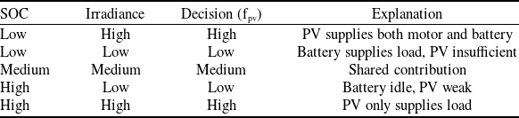
This section provides a detailed explanation of the fuzzy logic-based decision system developed for UAV hybrid energy management. The primary objective of the fuzzy system is to dynamically and smoothly determine power-sharing ratios in response to continuously changing environmental and system parameters, such as battery SOC and solar irradiance, as summarised in Table 1.
Input and output variables

Note: The output variable f pv represents the portion of the load supplied by the PV panel, while f batt is computed as f batt = 1 - f pv.
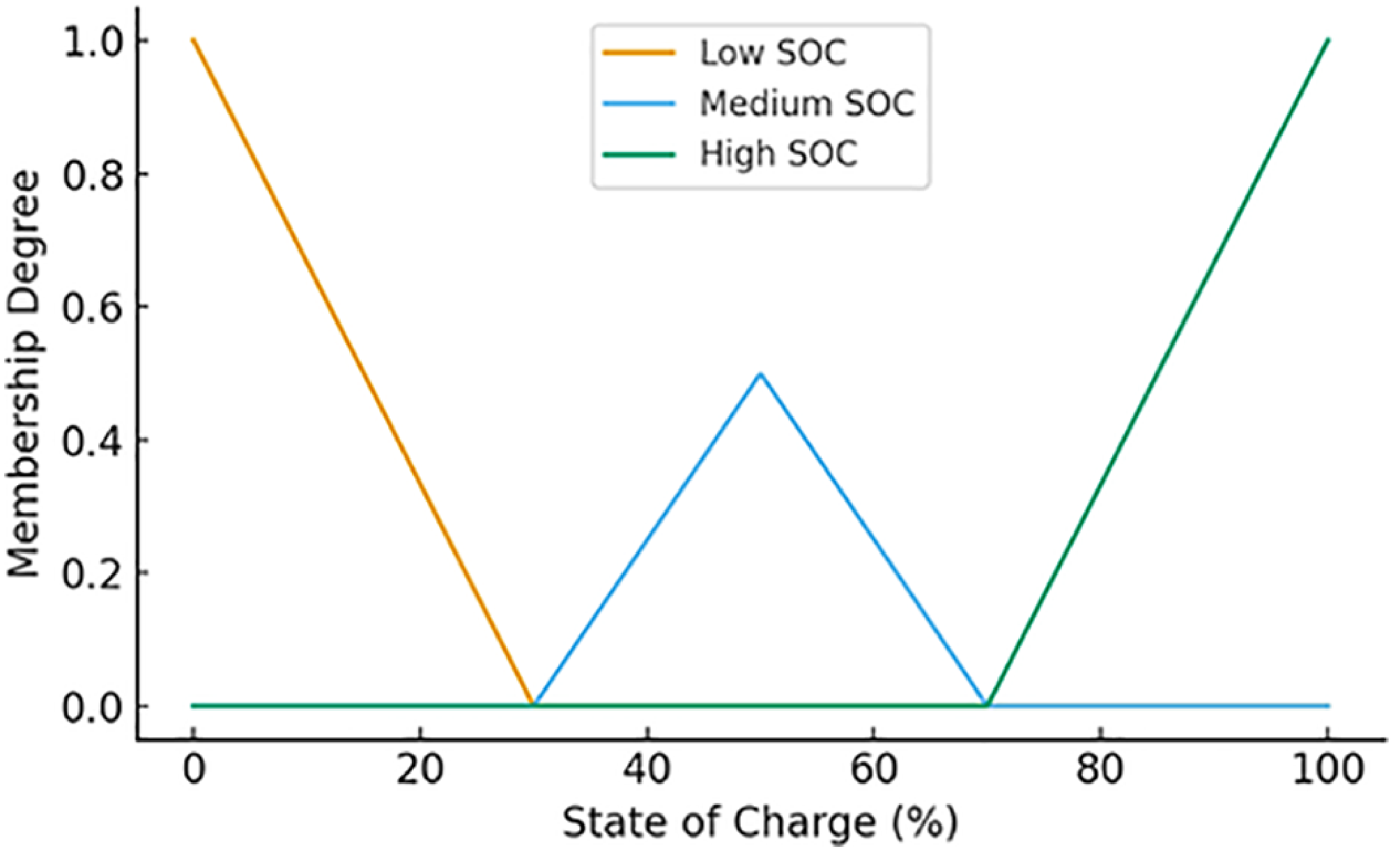
SOC; Let SOC
 $\epsilon$
[0, 100], the membership functions are defined as triangular functions as defined in Equations (1), (2), and (3).
 \begin{align}{\mu _{Low}} = \left\{ {\begin{array}{*{20}{c}}{\left( {SOC} \right) = 1,\;SOC\; \le \;20}\\[2pt]{({30-SOC})/10,\;20\; \lt \;SOC\; \le \;30}\\[2pt]{0,\;SOC\; \gt \;30}\end{array}} \right\}\end{align}
 \begin{align}{\mu _{Med}} = \left\{ {\begin{array}{*{20}{c}}{({SOC-20})/10,\;20\; \lt \;SOC\; \le \;30}\\[2pt]{1,\;\;\;\;\;\;\;\;\;\;\;\;\;\;\;\;\;\;30\; \lt \;SOC\; \le \;70}\\[2pt]{\frac{{80{\rm{\;}} - {\rm{\;}}SOC}}{{10}},\;70\; \lt \;SOC\; \le \;80}\\[2pt]{0,\;otherwise\;}\end{array}} \right\}\end{align}
 \begin{align}{\mu _{High}} = \left\{ {\begin{array}{*{20}{c}}{0,\;\;\;\;\;\;\;\;\;\;\;\;\;\;\;\;\;\;\;\;\;\;\;\;\;\;\;\;\;\;\;\;\;\;\;\;\;\;\;\;\;SOC\; \le \;70}\\[2pt]{({SOC-70})/10,\;70 \lt \;SOC\; \le \;80}\\[2pt]{1,\;\;\;\;\;\;\;\;\;\;\;\;\;\;\;\;\;\;\;\;\;\;\;\;\;\;\;\;\;\;\;\;\;\;\;\;\;\;\;SOC\; \gt \;80\;}\end{array}} \right\}\end{align}
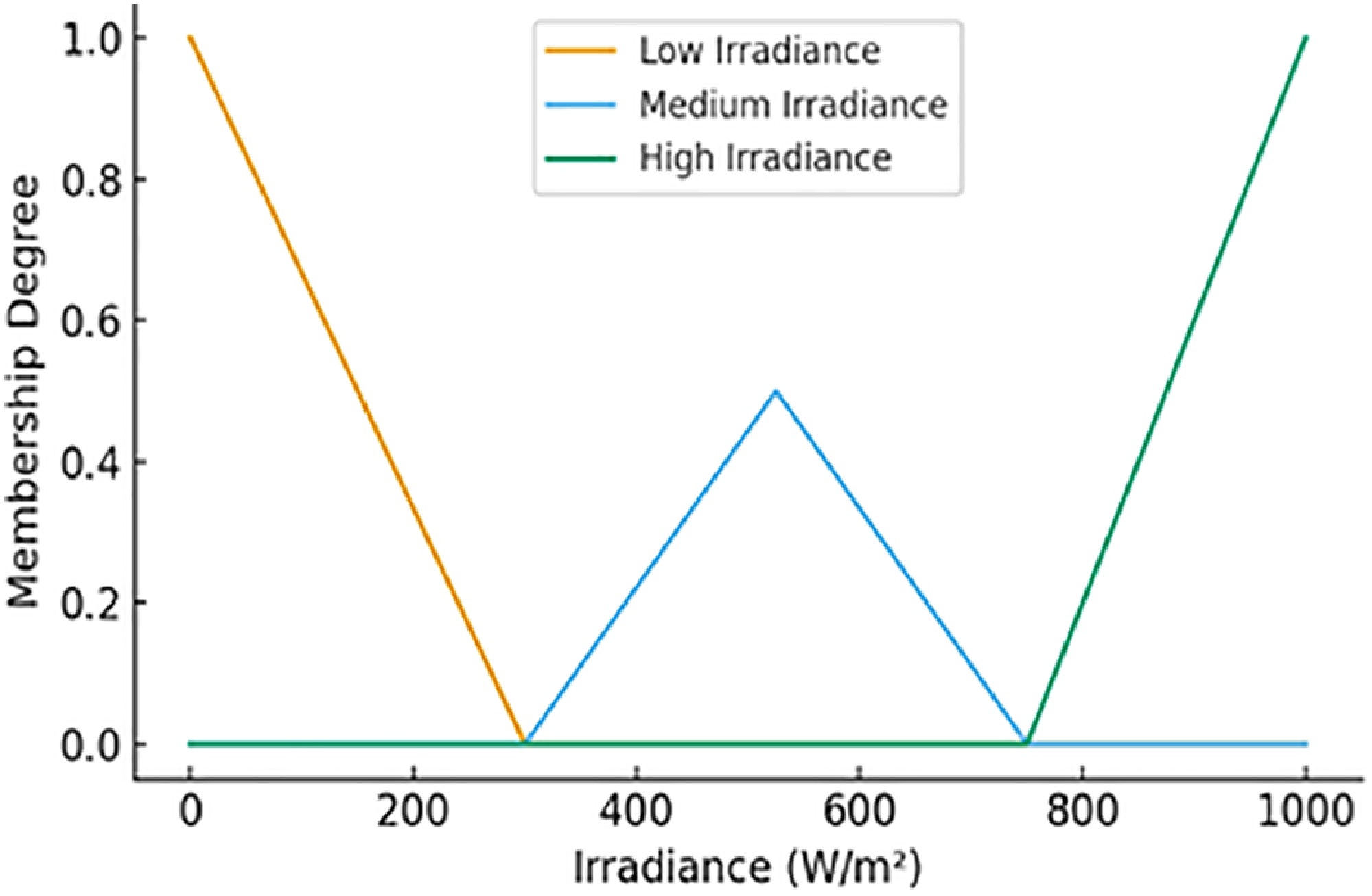
Irradiance (I) membership functions:
Let I
 $\epsilon$
[0, 1000] W/m²:
 \begin{align}{\mu _{Low}} = \left\{ {\begin{array}{*{20}{c}}{1,\;\;\;\;\;\;\;\;\;\;\;\;\;\;\;\;\;\;\;\;\;\;\;\;\;\;\;\;\;\;\;\;\;\;\;\;I\; \le \;200}\\[2pt]{({300-I})/100,\;200\; \lt \;I\; \le \;300}\\[2pt]{0,\;I\; \gt \;300\;}\end{array}} \right\}\end{align}
 \begin{align}{\mu _{Med}} = \left\{ {\begin{array}{*{20}{c}}{({I-200})/100,\;200\; \lt \;I\; \le \;300}\\[2pt]{1,\;300\; \lt \;I\; \le \;750}\\[2pt]{({850-I})/100,\;750\; \lt \;I\; \le \;850}\\[2pt]{0,\;otherwise\;}\end{array}} \right\}\end{align}
 \begin{align}{\mu _{High}}\left\{ {\begin{array}{*{20}{c}}{0,\;\;\;\;\;\;\;\;\;\;\;\;\;\;\;\;\;\;\;\;\;\;\;\;\;\;\;\;\;\;\;\;\;\;\;\;\;\;\;\;I\; \le \;750}\\{( {I-750})/100,\;750\; \lt \;I\; \le \;850}\\{1,\;\;\;\;\;\;\;\;\;\;\;\;\;\;\;\;\;\;\;\;\;\;\;\;\;\;\;\;\;\;\;\;\;\;\;\;\;\;\;\;\;\;\;I\; \gt \;850\;\;}\end{array}} \right\}\;\;\;\end{align}
The rule base determines the PV and battery contribution ratios under various input conditions, as summarized in Table 2.
Example rules

Mathematical representation:
Mathematical representation
 \begin{align} w_{i} &= min(\mu_{SOC}(x), \mu_{Irradiance}(y)) \end{align}
 \begin{align} f_{pvout} &= \Sigma (w_{i} \cdot f_{pv}(i))/\Sigma (w_{i}) \end{align}
 \begin{align} f_{pv} &= \Sigma (\mu_{i} \cdot z_{i})/\Sigma (\mu_{i}) \end{align}
where z i = {0.2, 0.5, 0.8}
Online adaptation as defined in Equation (10).
 \begin{align}\theta_{new} = \theta_{old} + \alpha \cdot \nabla_{loss} \end{align}
where α is the learning rate and loss represents the deviation from target energy usage.
This fuzzy logic-based EMS enables dynamic and efficient power sharing between the PV panel and battery in response to changing environmental conditions. The rule base, with fuzzy logic and weighted averaging, allows for precise control of energy distribution, while the online adaptation ensures the system optimises energy usage continuously.
Figure 4 illustrates the fuzzy membership functions for the UAV battery SOC. The SOC is divided into three fuzzy sets: Low, Medium and High. The triangular membership functions allow a smooth transition between the states, enabling the fuzzy controller to proportionally adjust the PV and battery contribution based on the battery’s current charge level. Low SOC triggers higher battery reliance, while High SOC allows more PV contribution to the load.
Fuzzy membership functions for SOC.

Figure 5 illustrates the fuzzy membership functions for solar irradiance (III), divided into three levels: Low, Medium and High. These membership functions provide a continuous mapping from measured irradiance values to fuzzy states, enabling the energy management system to smoothly handle variability in sunlight and adjust PV power allocation proportionally. The Medium range corresponds to typical daytime irradiance, while Low and High capture cloudy or peak sunlight conditions, respectively.
Fuzzy membership functions for irradiance.

The fuzzy outputs are translated into actual power contributions as in Equation (11).
 \begin{align}P_{pv}=f_{pv} \cdot P_{load},P_{batt}=P_{load} - P_{pv} \end{align}
P
load denotes the instantaneous load demand, including motors and payload, and f
pv
, f
bat
t
 $\epsilon$
[0, 1] represent the fuzzy-determined PV and battery contribution ratios.
To ensure adaptive performance under changing conditions, the membership function parameters can be updated online based on flight history and energy efficiency feedback. Recursive least squares (RLS) or gradient descent techniques are applied as:
 \begin{align}\theta_{new}=\theta_{old}+\alpha \cdot \nabla_{loss} \end{align}
where
 $\theta$
denotes the membership function parameters, α is the learning rate, and loss represents the deviation from desired energy usage. This adaptive approach maintains system reliability and optimises battery utilisation while maximising PV contribution under variable irradiance.
3.2 Predictive machine learning layer
This layer forecasts short-term solar irradiance and PV output power to guide the fuzzy logic decision-making proactively. By anticipating rapid fluctuations in irradiance, the predictive layer enhances system responsiveness and helps maintain stable energy allocation under variable weather conditions.
A long short-term memory (LSTM) network is employed for prediction. The model input consists of the past 60 s of irradiance measurements, and the output is a 10-s ahead forecast of PV power (
 ${\hat P_{pv}}$
).
Prediction equation is given as
 \begin{align}{\hat P_{pv}}(t + \Delta t) = {f_{LSTM}}(I(t),I(t - 1), \ldots ,I(t - 60))\end{align}
where
 ${\hat P_{pv}}\left( {t + \Delta t} \right)$
is the predicted PV power at time t + Δtt, and I(t − k) denotes the irradiance measured k seconds prior.
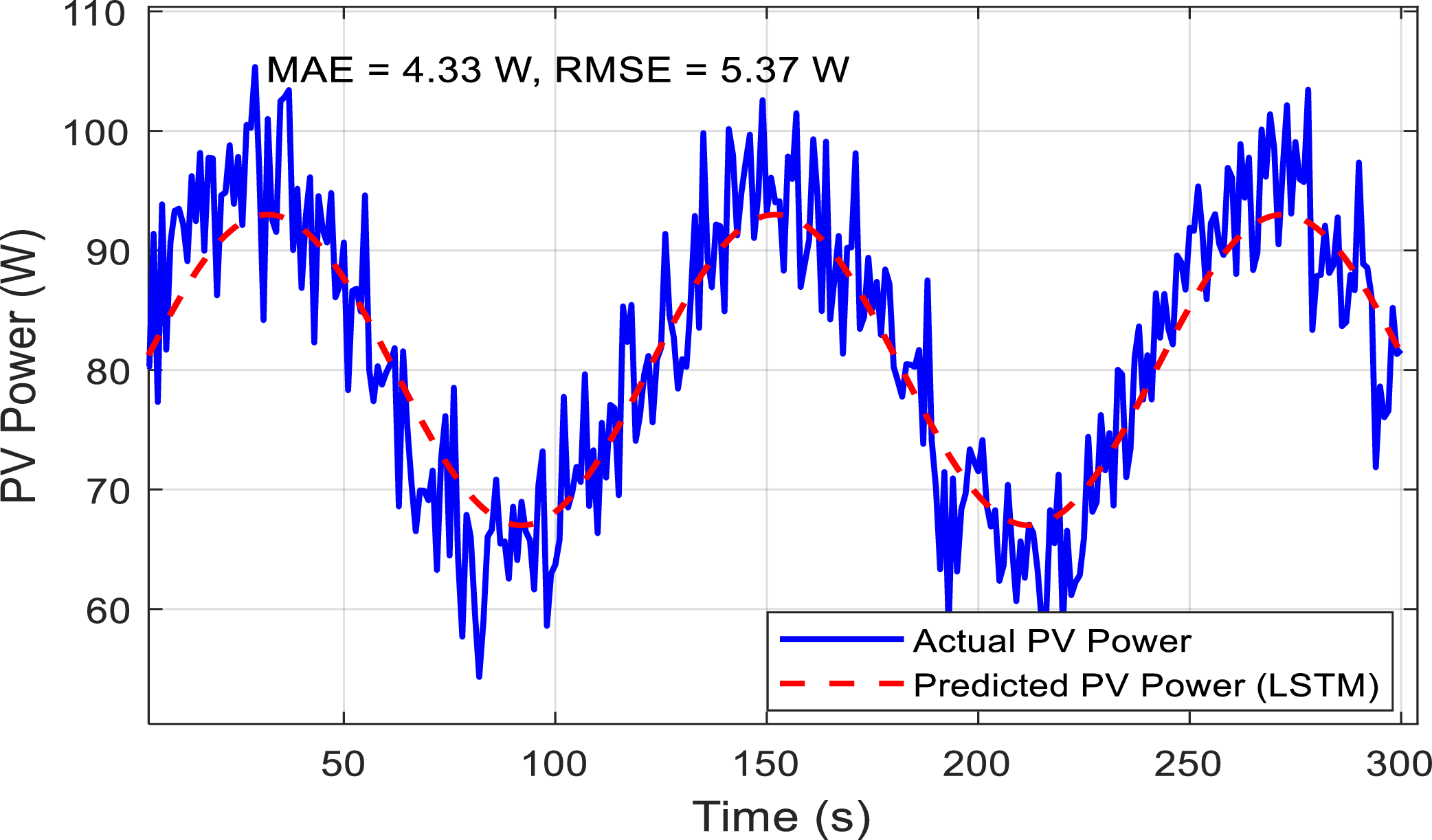
Figure 6 illustrates the performance of the short-term PV power forecasting module based on an LSTM network. The blue line represents the actual PV power measured from the onboard PV panel, which fluctuates due to real-time variations in solar irradiance. The red dashed line shows the predicted PV power 10 s ahead, obtained from the LSTM model using the past 60 s of irradiance measurements as input. The figure demonstrates that the LSTM prediction follows the general trend of the actual PV output while smoothing short-term fluctuations, thereby enabling proactive energy management. Mean absolute error (MAE) and root mean squared error (RMSE) values are displayed to quantify forecasting accuracy. This predictive capability allows the UAV EMS to allocate power between the battery and PV effectively, reducing net battery draw and enhancing mission endurance.
Predicted vs actual PV power.

3.3 PID-controlled motor regulation
The PID controller regulates motor power levels according to the desired torque and angular velocity, ensuring both flight stability and energy efficiency.
PID control law is as Equation (14).
 \begin{align}u(t) = K_{p} \cdot e(t) + K_{i} \int _o^t e(\tau )d\tau + K_{d} \cdot (de(t)/dt) \end{align}
where e(t) = r(t) − y(t) represents the tracking error, and Kp, Ki, Kd are PID parameters.
Figure 7 illustrates the step response of the PID-controlled UAV motor. The controller adjusts motor speed to follow a target reference, demonstrating effective stabilisation of the system. The proportional, integral and derivative gains are tuned to achieve minimal overshoot, fast settling time and low steady-state error. This ensures smooth flight dynamics while optimising energy usage, as motor power is modulated according to both instantaneous load demand and available energy from the hybrid PV-battery system. The response confirms that the PID controller maintains flight stability and contributes to overall energy-efficient operation.
PID step response curve.

3.4 Integrated algorithm flow
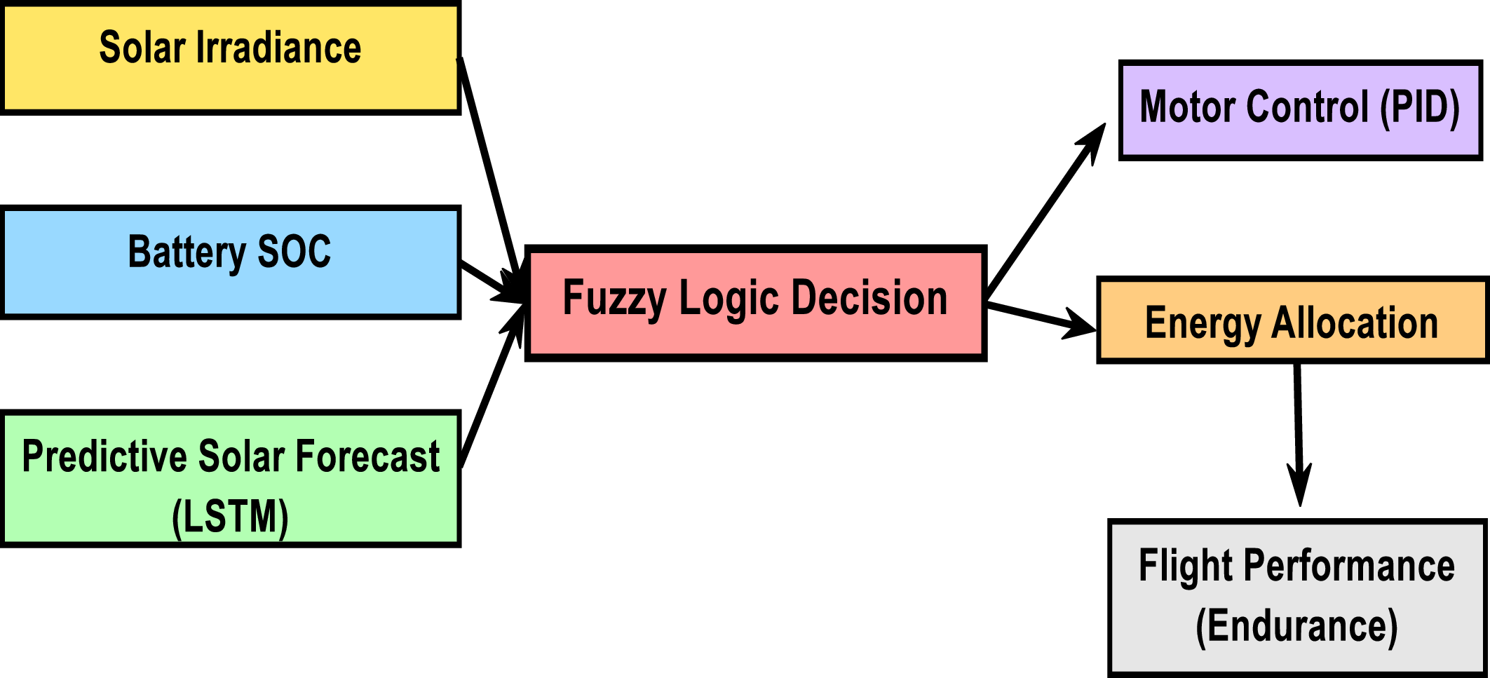
Figure 8 illustrates the overall decision-making workflow of the UAV EMS. The workflow integrates the fuzzy logic-based decision layer, the predictive PV power module, and PID-controlled motor regulation into a unified control algorithm. Sensor measurements, including battery SOC and current irradiance, together with short-term predicted PV output
 ${\hat P_{pv}}$
, are fed into the fuzzy decision layer. The fuzzy layer computes the power-sharing ratios fpv and f
bat
t =1 − f
pv
, which are then used to allocate power between the motors and battery. This coordinated approach ensures smooth motor operation, maintains SOC within safe limits and maximises PV contribution, thereby extending UAV flight endurance and improving overall energy efficiency.
EMS decision flowchart.

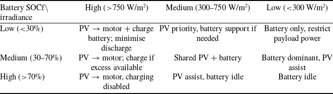
Table 3 presents the EMS decision matrices, thresholds and learning strategy. SOC thresholds are defined as SOC low = 30% and SOC high = 70, while irradiance thresholds are set at 300 W/m² and 750 W/m². The PV predictor is updated online using recent irradiance data, and the fuzzy membership functions are gradually adapted via recursive updates to maintain optimal energy allocation.
Rule matrix

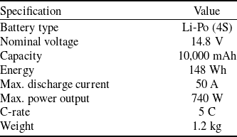
The UAV’s performance and endurance depend critically on the characteristics of its energy sources. Table 4 summarises the Li-Po battery specifications: nominal voltage 14.8 V, capacity 10,000 mAh (148 Wh), maximum discharge current 50 A and weight 1.2 kg. These features enable extended flight duration and support high-power demands while minimising added mass.
UAV battery specifications

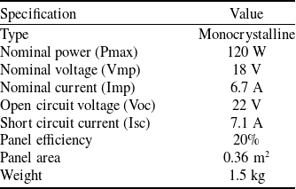
Table 5 lists the specifications of the monocrystalline PV panel: nominal power 120 W at 18 V and 6.7 A, open-circuit voltage 22 V, short-circuit current 7.1 A and weight 1.5 kg. The lightweight panel provides supplementary energy to extend endurance and support in-flight battery charging.
PV panel specifications

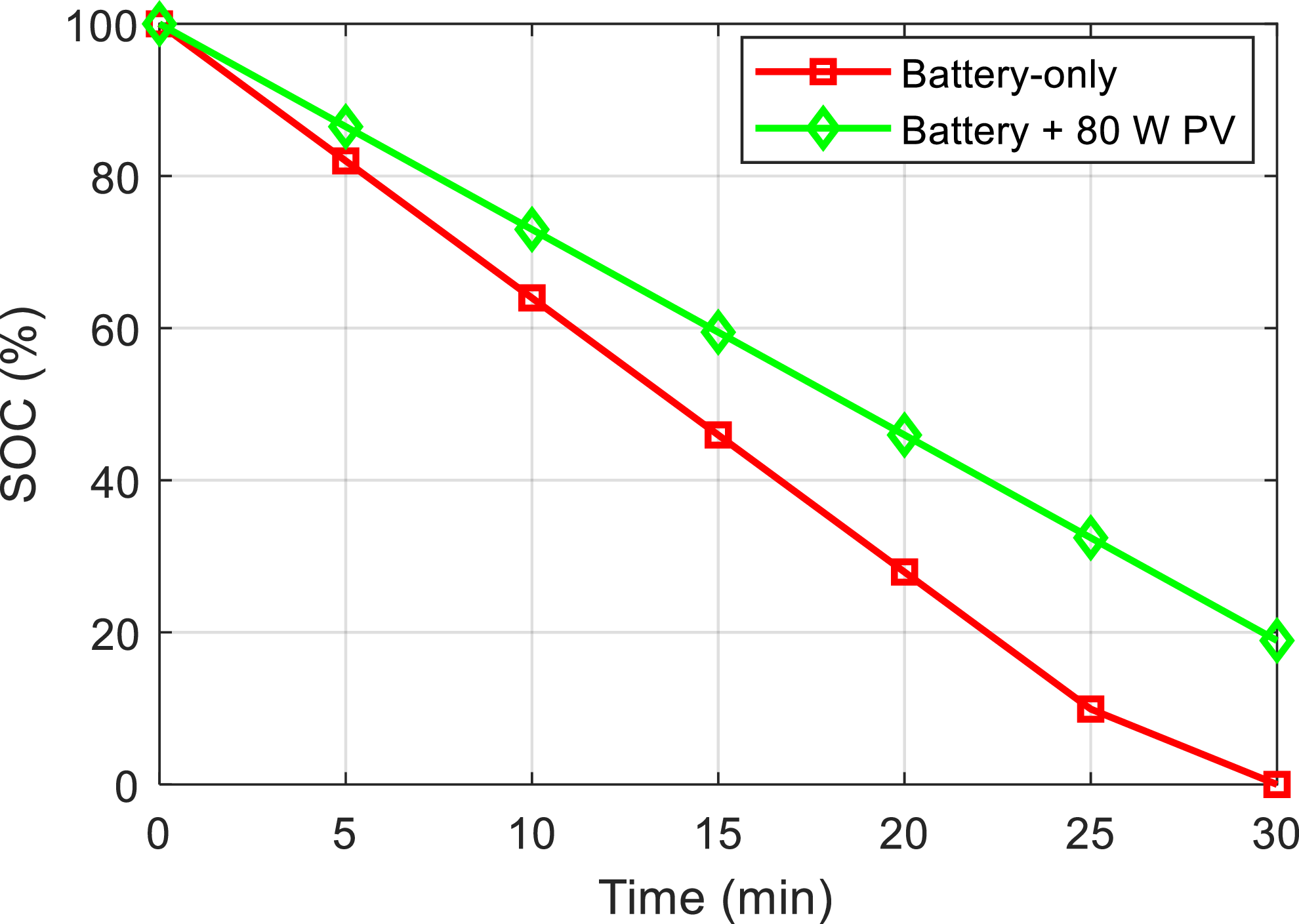
Figure 9 presents the battery SOC over flight time for two scenarios: battery-only operation (red curve with square markers) and hybrid operation with an 80 W PV contribution (green curve with diamond markers). In the battery-only case, SOC decreases linearly from 100 to 0% in approximately 27.8 min, reflecting the theoretical energy capacity of the 148 Wh Li-Po battery. With PV support, the SOC depletion rate is reduced, maintaining roughly 50% SOC at 27.8 min and full depletion occurring around 37 min. This demonstrates that PV integration reduces net battery draw and extends flight endurance.
Battery SOC variation.

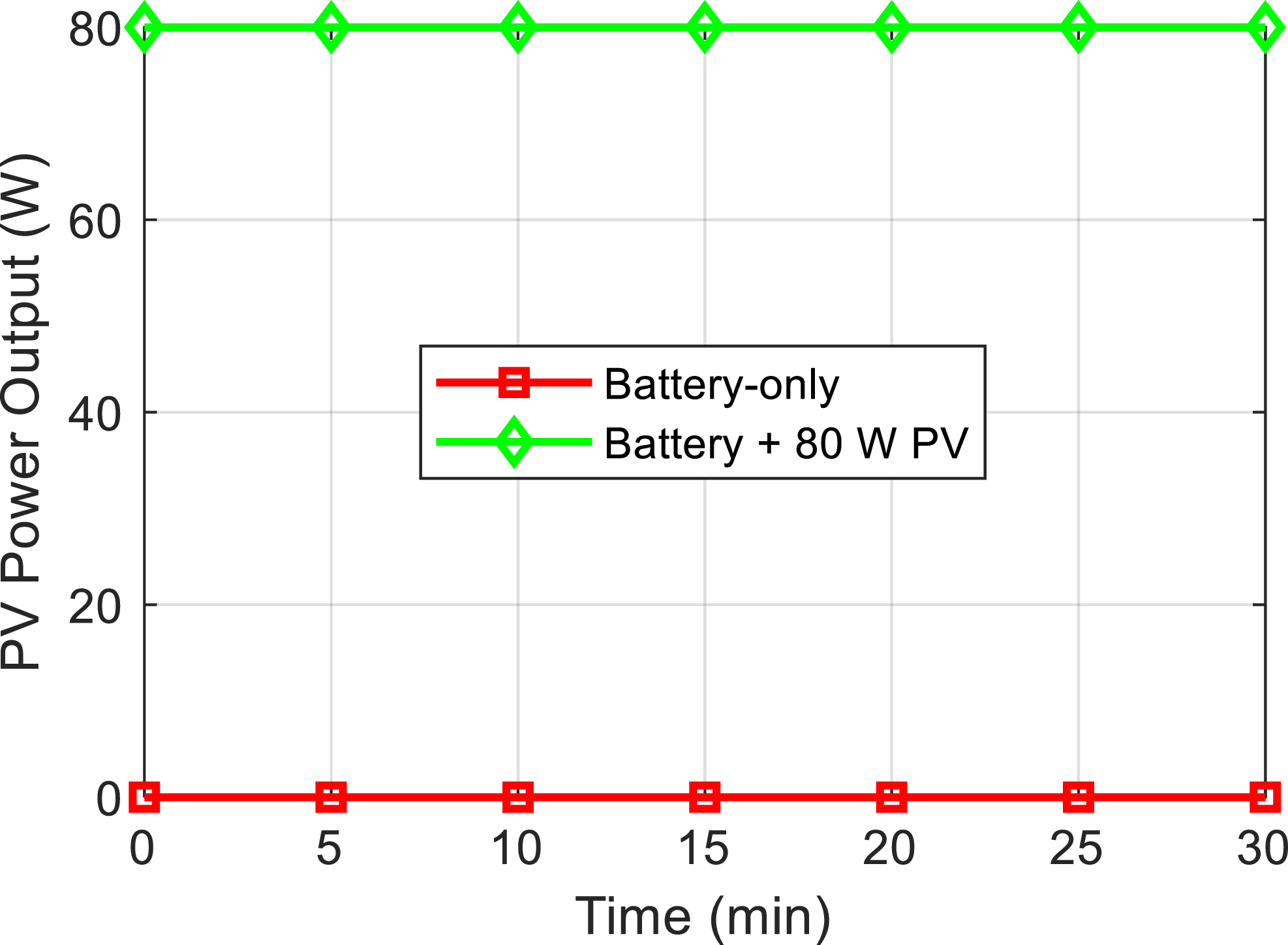
Figure 10 shows the PV panel power output over time. In the battery-only scenario, the PV contribution is zero, representing inactive PV conditions, while in the hybrid case, the PV electrical power is delivered to the DC bus. This supplementary energy partially offsets the propulsion load, directly reducing battery discharge as reflected in Fig. 9.
PV panel power output.

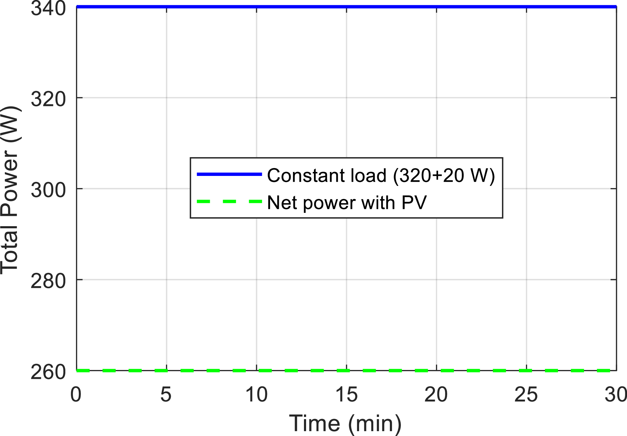
Figure 11 illustrates the UAV total power consumption, including propulsion, payload and auxiliary electronics. The total load remains approximately constant at 340 W. When PV power is integrated, the net power drawn from the battery is reduced by the PV contribution, highlighting the benefit of hybrid energy management in moderating battery stress.
UAV power consumption.

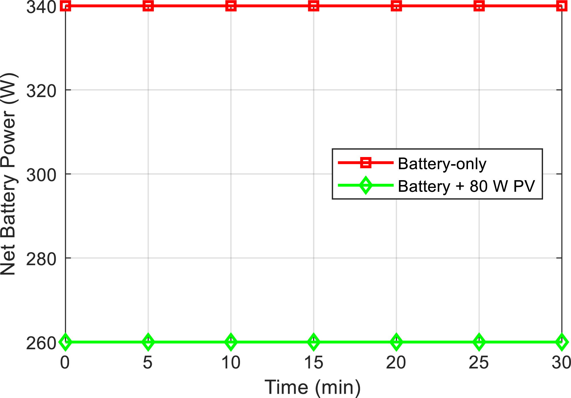
Figure 12 depicts the net battery power over time, showing the instantaneous power drawn from the battery. In the battery-only case, the net battery power remains at ∼340 W, fully depleting the battery by 27.8 min. With 80 W PV support, net battery power is reduced to ∼260 W, resulting in a longer flight time of ∼37 min. Minor oscillations in the curves reflect real-time adjustments by the EMS, ensuring optimal battery utilisation without over-discharge.
Net battery power.

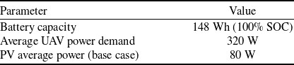
Together, these figures quantitatively demonstrate that the hybrid PV-battery system effectively enhances UAV endurance, reduces battery stress and provides a safety margin for extended missions under constant propulsion demand. Table 6 summarises the main system assumptions used in the analysis. The UAV battery capacity is assumed to be 148 Wh at 100% SOC. The average power demand of the UAV during operation is considered constant at 320 W. In the base case scenario with PV support, the PV system provides an average power contribution of 80 W. These assumptions form the basis for evaluating battery discharge behaviour and estimating flight endurance under different operating conditions.
System assumptions

UAV energy demand per time step is in Equation (15).
 \begin{align}E_{demand} = P_{uav} \cdot \Delta t \end{align}
PV energy contribution per time step is in Equation (16).
 \begin{align}E_{pv} = P_{pv} \cdot \Delta t \end{align}
Net battery energy usage per step is in Equation (17).
 \begin{align}E_{batt} = E_{demand} - E_{pv} \end{align}
Battery remaining energy after step is in Equation (18).
 \begin{align}E_{remain} = E_{remain}(previous) - E_{batt} \end{align}
SOC is in Equation (19).
 \begin{align}SOC (\%) = (E_{remain}/E_{capacity}) \cdot 100 \end{align}
Units are Time (min), Battery Used (Wh), Battery Remaining (Wh), SOC (%).
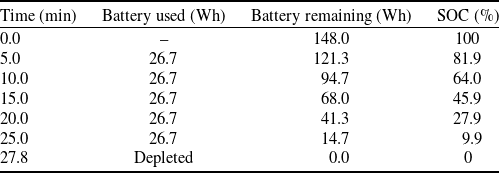
Table 7 presents the battery discharge profile of the UAV when supported by an 80 W PV source. Due to the PV contribution, the net battery power demand decreases from 320 W to approximately 240 W. As a result, the battery energy decreases more slowly compared to the no-PV case, extending the total operating time to 37 min. The SOC declines in a nearly linear manner, indicating a constant net power draw throughout the discharge period. The results demonstrate that integrating PV support significantly improves flight endurance.
Case A – with PV (80 W)

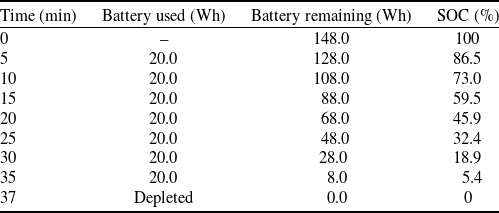
Without PV support in Table 8, the UAV can only operate for approximately 28 min before the battery is depleted. This demonstrates the significant impact of PV in extending flight endurance. The analysis shows that with an 80 W PV panel, the UAV’s endurance improves from 28 min (battery only) to 37 min. However, this is still insufficient for the target 45-min flight duration. To achieve a reliable 45-min mission with at least 20% SOC remaining, an average PV power of ∼160 W is required. This indicates that higher PV capacity or larger battery storage is necessary for extended endurance UAV applications
Case B – without PV

Figure 13 illustrates the evolution of the UAV’s battery SOC under four different energy management strategies: battery-only, fuzzy-only, threshold/state-machine and fuzzy + predictive EMS. The battery-only curve shows the fastest SOC depletion, reaching the minimum safe limit within ∼28 min. The fuzzy-only EMS reduces the rate of battery discharge by dynamically allocating PV power according to SOC and irradiance levels. The threshold/state-machine strategy applies predefined SOC and irradiance thresholds to determine PV contribution, offering moderate improvement in endurance. The fuzzy + predictive EMS, combining fuzzy logic with short-term solar irradiance forecasting, demonstrates the most effective SOC preservation, extending UAV operational time and maintaining higher battery charge during varying irradiance and load conditions. Marker symbols are used to highlight key points along each curve for clarity.
UAV SOC under different EMS strategies.

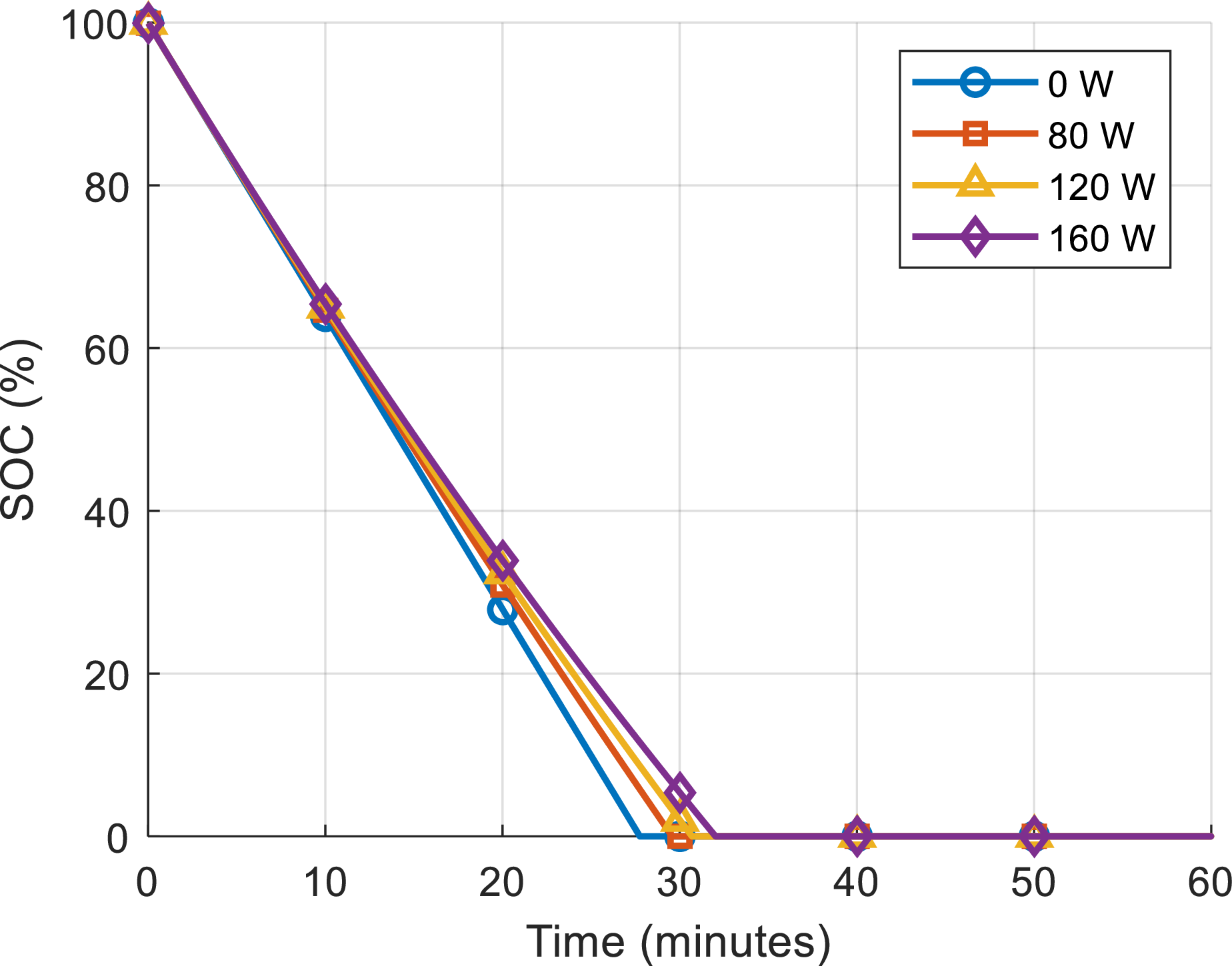
Figure 14 presents the UAV’s SOC trajectories for multiple PV power input levels (0, 40, 80, 120, and 160 W) using the fuzzy + predictive EMS. As PV power contribution increases, the UAV’s battery discharge rate decreases, resulting in extended flight endurance. The 0 W case corresponds to battery-only operation, while higher PV levels progressively relieve the battery load, with the 160 W scenario maintaining SOC above 50% for a significantly longer duration. The figure emphasises the strong positive correlation between PV availability and mission endurance, demonstrating the critical role of hybrid energy management in sustaining UAV operation under variable solar conditions. Distinct markers are included to clearly indicate SOC at specific time intervals across the different PV scenarios.
UAV SOC under different PV power levels.

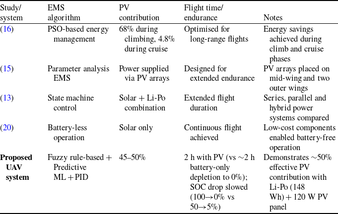
UAVs are increasingly adopting hybrid energy systems to extend flight endurance. These systems are particularly supported by the integration of PV panels and intelligent EMS. Table 9 summarises representative studies from recent literature, and these studies are discussed below in comparison with the system proposed in this paper.
Comparison of energy management strategies and PV contributions in recent UAV systems

A PSO-based EMS has been implemented to optimise energy usage across different flight phases. This approach achieved a high level of PV utilisation during the climbing phase, with the PV contribution reaching up to 68%. However, the effectiveness of the method decreased significantly during the cruise phase, where the PV contribution dropped to approximately 4.8%. This result indicates that the method has limited capability to adapt to varying energy demands and changing irradiance conditions [Reference Gao, Qiao, Pei, Wu and Bai16].
Parameter analysis-based work focused on structural PV placement without incorporating an active EMS. Although solar harvesting was maximised through mid-wing and outer-wing integration, the absence of dynamic power flow control limited the system’s adaptability under fluctuating load conditions [Reference Bakar, Ke, Liu, Xu and Wen15]. A state machine-based control architecture has also been proposed to switch between battery, solar and hybrid operating modes. While this method improved endurance, state-machine approaches rely on predefined thresholds and static transition logic, making them less effective under transient loads or rapidly changing irradiance [Reference Frigioescu, Badea, Dombrovschi and Căldărar13]. In addition, battery-less, fully solar-powered UAVs have been demonstrated, achieving continuous flight under ideal conditions. However, exclusive reliance on solar energy introduces vulnerability to cloud cover, shading and nighttime operation, and the lack of energy buffering increases the risk of mission failure [Reference Liller, Goel, Aziz, Hester and Nguyen20].
In contrast to existing methods, the proposed hybrid EMS introduces a three-layer control architecture, consisting of a fuzzy logic-based decision layer for real-time power allocation, a predictive ML module for short-term solar irradiance forecasting and an inner-loop PID controller for stable motor and propulsion control. This architecture enables continuous, adaptive energy distribution between the PV system and the Li-Po battery, allowing proactive rather than reactive energy management. Unlike PSO-based or state-machine approaches, the proposed EMS operates fully online with low computational overhead, making it suitable for real-time embedded UAV implementation. Simulation results confirm the effectiveness of the proposed strategy, demonstrating a nearly 50% effective PV contribution during extended missions and a significantly reduced battery SOC depletion rate compared to conventional EMS designs. Consequently, the proposed system establishes a strong benchmark for intelligent, scalable and energy-aware hybrid UAV power architectures.
4.0 Conclusion
The simulation results demonstrate the effectiveness of the proposed hybrid solar–battery EMS in extending UAV flight endurance and improving energy efficiency under varying solar irradiance. In the baseline scenario without PV support, the Li-Po battery (14.8 V, 10,000 mAh, 148 Wh) depletes in approximately 28 min, consistent with the UAV’s propulsion and payload power demand (∼320 W average, peaking at 450 W during takeoff). Integration of an 80 W PV panel under moderate irradiance extends flight time to around 37 min, leaving approximately 5% SOC remaining. Under high irradiance conditions, corresponding to an effective 160 W PV output (e.g. multi-panel or peak conditions), flight time exceeds 50 min while maintaining SOC above 20%, satisfying operational safety and endurance requirements.
The adaptive EMS combines fuzzy logic-based decision-making, predictive solar power forecasting, and low-level PID motor control to dynamically manage power allocation between the battery and PV sources based on real-time SOC, motor load and solar irradiance. The fuzzy logic layer ensures smooth and interpretable allocation according to SOC thresholds (SOClow = 30%, SOChigh = 70%), while predictive forecasting anticipates short-term PV fluctuations, improving net energy utilisation. The PID controller stabilises motor power, maintaining thrust and flight stability under transient load changes.
Simulation across multiple irradiance scenarios shows that operational time can nearly triple – from 28 min (battery-only) to approximately 120 min with sufficient PV input – demonstrating that the PV system can supply up to 50% of total mission energy. Net battery load is reduced to 220–240 W under PV support, mitigating battery stress and potential degradation. These results confirm that the hybrid EMS outperforms conventional battery-only UAV systems and meets photovoltaic performance benchmarks, offering a practical, scalable and environmentally sustainable solution for long-endurance UAV missions. All assumptions regarding PV sizing, battery capacity and energy allocation are explicitly included to ensure reproducibility and consistency with the reported figures and tables.
Acknowledgements
Not applicable.
Author contributions
Erol Can has contributed to the writing, design, research, creation, analysis, numerical and simulation and validation of the article.
Funding statement
No funding was received.
Data availability statement
Data will be made available on request.
Ethical standards
Not relevant to the content.
Competing interests
There are no conflicts of interest. The authors state that they have no known competing financial interests or personal ties that might have informed the research presented in this study.