I. INTRODUCTION
In recent years, the number of wireless charging devices has increased in the electronics market. Wireless charging has many applications, including in medical electronics [Reference Hou, Jia, Feng, Mao and Cheng1], wireless communication [Reference Scheible, Schutz and Apneseth2], as well as consumer and sensor applications [Reference Waffenschmidt and Staring3]. This technology has the advantage that there are no sparks, which eliminates risks in environments where explosive materials are present. It enables devices to be hermetically sealed. It allows different objects to be recharged with a single charger at different orientations. Wireless charging allows objects to be charged during use and while moving, for example a sensor on a moving piece of machinery.
Wireless power transfer traditionally uses inductive coupling between a transmitter and receiver inductor coil. Various research have been done on coil design for wireless power systems. For example, in litz wire coils, losses in inductor coils were examined in [Reference Mahomed, Hofsajer, Cronje, Odendaal and Holm4, Reference Sullivan5]. Coils in printed circuit boards (PCBs) have also been widely used for wireless charging applications [Reference Choi, Nho, Cha, Ahn and Choi6, Reference Jow and Ghovanloo7]. Multiple layer coils in flex substrates have also been studied in [Reference Yu, Herrault, Ji, Kim, Allen and Lisi8]. Bond-wires on a PCB substrate arranged as coils have also been suggested in [Reference Lin, Chiou, Wu, Chen, Ko and Juang9].
In order to increase the coupling coefficient, and thereby the efficiency, of a wireless power link, there have been efforts to achieve a more homogeneous coupling factor for wireless charging platforms. For example, Casanova has done a simulation analysis of a square-shaped planar coil, where the windings have a staggered separation distance to achieve a more homogeneous magnetic field above the coil [Reference Casanova, Low, Lin and Tseng10]. Waffenschmidt has conducted a similar study using circular coils in litz wire technologies [Reference Waffenschmidt11]. These papers have shown that is it possible to arrive at a very homogeneous magnetic field distribution by carefully staggering the distance between the windings of the coil.
Various papers have also investigated placing coils in an array configuration, so that the transmitter coil can achieve a much larger charging area. Square coils were used by Matsumoto et al. [Reference Matsumoto, Neba, Ishizaka and Itoh12], where the coils were excited with three different phases. Square coils were also used by Yinliang et al. [Reference Yinliang, Yuanmao and Yougang13], where two coils, with staggering to improve magnetic field homogeneity, were placed adjacently or overlapping. Matsumoto limited his research to coils in a straight line and Yinliang limited his research to only two parallel or overlapping square coils. Therefore, these papers have neglected the case where four square coils are arranged in an array and come to a corner. Ahn et al. [Reference Ahn, Park, Choi, Kim, Song and Park14] investigate this case, where it is shown that, in general, a very homogeneous field distribution can be achieved but only with exceptions. An array of four square transmitter coils introduces areas where the fields cancel each other, resulting in areas where the coupling coefficient between the transmitter and receiver coils is nearly zero.
Circular coils, usually overlapping, have also been used in wireless charging platforms. Ma and Ma in [Reference Ma and Ma15], use circular planar PCB coils, overlapping in three different layers, to achieve a charging platform with no areas where the magnetic field is cancelled out. However, the field strength is much stronger in the middle. This would be an advantage for certain applications but a disadvantage for others. In [Reference Sun, Teng, Li and Pan16], circular coils were simulated by Sun et al. in an array form. In a simple single-layer array configuration, Sun et al. achieve a magnetic field across the entire platform; however, little attention is given to the homogeneity of the coupling coefficients. Shen et al. [Reference Shen, Lee and Chang17] and Zhong et al. [Reference Zhong, Liu and Hui18] have also built arrays of circular coils using litz wire and ferrite cores, respectively. Like Sun et al., they achieve a link over a large area platform, but little attention is made to homogeneity and the resulting transmitters are much thicker, due to the integration of the ferrite cores.
Hexagonal coils offer the advantage that they fit better in an array configuration but, unlike square coils, do not necessarily have magnetic field cancellation spots. Overlapping hexagons, for example, have been presented by Jow and Ghovanloo in [Reference Jow and Ghovanloo19] for a sensor application. Very significant research has been conducted by Liu and Hui in a series of papers [Reference Liu and Hui20–Reference Hui and Ho23] regarding hexagonal wireless charging platforms. Additionally, Achterberg presents a mixed approach with square and hexagonal coils stacked in different layers [Reference Shamonina, Kalinin, Ringhofer and Solymar24]. Although this research is very significant and represents the most advanced approach, it also has certain disadvantages. For example, the approach places hexagonal coils overlapping in different layers. This makes it difficult to implement the cheapest manufacturing technologies such as through-vias. And while the research improves the homogeneity of the fields on the platform to improve the efficiency, it pays little attention to the resistance of the coil. Waffenschmidt [Reference Waffenschmidt11] has presented a charging platform with staggered coils in a single layer that requires the receiver coil to be less than half the size of the transmitter coil. Although this is an excellent advancement that would allow for reduced cost charging platforms, it poses a significant challenge for small devices because the transmitter coils must remain so small.
Creating a magneti-inductive waveguide, with multiple coils resonating has been another approach for creating large area wireless power transfer platforms. Shamonina et al. has proposed a magneto-inductive waveguide that uses many elements as a magnetic guide for magnetic resonance imaging [Reference Scheible, Schutz and Apneseth2 Reference Mahomed, Hofsajer, Cronje, Odendaal and Holm4]. Stevens [Reference Stevens25] has designed and modeled a magnetic relay system which generates a magneto-inductive wave, which provides 58% efficient power transfer to any point on its length. Puccetti et al. has designed and built a similar array of spiral resonators that are used to transfer power from a transmitter to a receiver [Reference Puccetti, Reggiani and Sandrolini26]. In [Reference Puccetti, Stevens, Reggiani and Sandrolini27], Puccetti et al. conduct an analysis to improve the performance of a multiple inductively coupled resonator coil system.
The goal of this paper is to propose a charging platform that uses a staggering of the windings of a coil to achieve a satisfactory coupling coefficient homogeneity, using square and hexagonal coils without overlapping. By not overlapping coils, one eliminates interaction between the coils on different layers. Resistance of the coils can be significantly decreased by connecting coils on different layers in parallel with through-via technology, thereby offering a higher degree of control over the efficiency, power-handling capability, and heat dissipation of the charging platform. The charging platform should be suitable for different receiver coils, of different sizes and shapes, representing different device sizes. The platform should also accommodate receiver coils of different heights, representing different coil integration in devices.
II. MODELING OF HOMOGENEITY IN SQUARE COILS
Publications have shown that planar coils, with evenly spaced turns, show a much stronger magnetic field above the center of the coil. By increasing the turn density toward the outside of the coil, one can increase the homogeneity of the magnetic field. In this section, we will focus on the homogeneity of the magnetic field when two square coils are adjacent to each other and how that translates into a coupling coefficient.
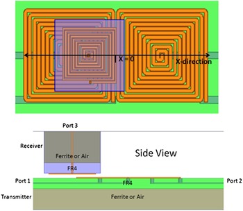
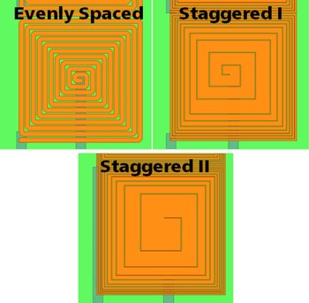
Two adjacent square transmitter coils were simulated with Ansys Maxwell 3D with a third receiver coil placed some distance above, as shown in Fig. 1. In this section, no ferrites were used in the simulation. Three different coils, each with 5 cm edges and ten turns, but with different spacing between the coils (different staggering) were compared as transmitter coils, which are shown in Fig. 2. The evenly spaced coil has conductor widths of 2 mm and gaps of 0.5 mm. The staggered I coil has gaps of 0.25 mm and widths of 0.75, 0.75, 0.75, 1, 1.25, 2, 2.5, 4.75 and 4.75 mm. The staggered III coil had gaps of 0.25 mm and widths of 0.5, 0.5, 0.5, 0.75, 0.75, 1.5, 1.5, 3 and 9 mm. Each coil has nine turns. The receiver coil remains an evenly spaced rectangular coil, which represents a generic device with a coil that the designers of the charging platform likely cannot control.
Diagram of the simulation model.

Three different coil geometries for comparison.

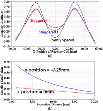
The receiver coil is shifted across the transmitter coils in the X-direction, where X = 0 mm means that the center of the receiver coil lies directly in the gap between the two coils and X = + /−25 mm means that the receiver coil is exactly centered over one of the receiver coils. Figure 3 shows the sum of the coupling coefficients of the receiver coil and each of the two transmitter coils. In this case, we are defining the coupling coefficient as the fraction of the flux generated by the first coil that flows through the second coil and vice versa [Reference Scheible, Schutz and Apneseth2 Reference Yu, Herrault, Ji, Kim, Allen and Lisi8]. When we examine, in Fig. 3(a), the evenly spaced square transmitter coils, we see that there is an excellent coupling when the coils are aligned but almost a zero point when the receiver coil lies at X = 0 mm. For the staggered transmitter coils, there is a significantly higher coupling at X = 0 mm, with a coupling coefficient above 0.25 for the most staggered coil. There is still a strong maximum when the coils are aligned but there are no longer any dead spots, where the coupling is nearly zero. Figure 3(b) shows that, when the separation distance between the receiver and transmitter increases, the coupling coefficient becomes more homogeneous. The two curves, one that represents the maximum coupling coefficient and on that represents the smallest, nearly converge as the separation distance increases from 1 to 20 mm.
Comparison of coupling coefficients for (a) three different coils as a receiver coil shifts across and (b) as a receiver coil is lifted above.

Based on these simulations, one can see that it is possible to achieve a coupling coefficient everywhere over two square transmitter coils >0.2, even at a very small separation distance. This coupling coefficient becomes more and more homogeneous as the distance between the receiver and transmitter increases.
III. INFLUENCE OF FERRITES ON COUPLING COEFFICIENT
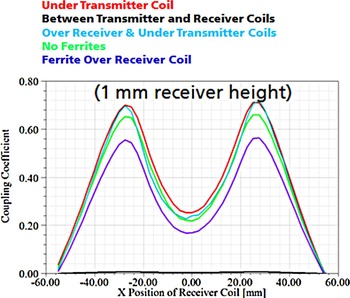
Adding ferrites to the structure, usually below the transmitter or above the receiver coil, was tested in the same simulation to see their effects on the coupling coefficient. When a ferrite is placed between the transmitter and receiver coils, then it acts as a shield leading to almost no coupling between the coils. When it is placed above the receiver coil only, it slightly reduces the coupling coefficient. Only when the ferrite is placed below the transmitter coil (with or without a ferrite above the receiver coil), is there a slight improvement in the coupling coefficient. That improvement, however, is <10%, for example an increase from 0.65 to 0.70 when the coils are in alignment, which is shown in Fig. 4.
Influence of ferrite placement on coupling coefficient.

IV. MODELING OF RESISTANCE AND INDUCTANCE
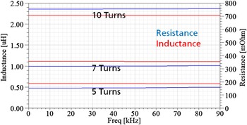
The link efficiency is not only dependent on the coupling coefficient, but also dependent on the quality factors of the coils. When the radius of the coil remains constant and the number of turns changes, while the maximum width of the turn remains the same, the inductance and resistance change exponentially. This occurs because, when the radius is constant, the inductance will be dependent on the square of the number of turns. Resistance increases exponentially because it will be dependent on the total length of the coil, which increases linearly with the number of turns, and inversely proportionally to the width of the conductor, which decreases approximately linearly with the number of turns.
What this means that the quality factor, which is proportional to the inductance and inversely proportional to the resistance, changes little when the inductance changes, for a given radius. This stability can be used to design coils for only through vias, which is a less expensive technology. The inductance for a given size coil can be determined by the number of coils and the resistance can be decreased by placing additional coils in parallel on additional layers in the PCB. Because they are all in parallel, they can easily be connected without blind or buried vias.
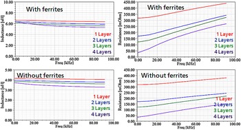
Ferrites can also be applied to a coil to increase its inductance and quality factor. Figure 6 shows an investigation of the inductance and resistance of the coils with and without ferrites underneath. The study shows that ferries raise the inductance by approximately 50%, with only a slight variation when additional coils are stacked in parallel. DC resistance with and without ferrites is also nearly identical. However, in the kHz frequency range, due to skin-effect and ferrite conductivity, there is an additional increase in the losses, especially in the cases where coils are stacked. In fact, despite the increase in the inductance from the ferrites, the quality factor of the coils in the kHz frequency range may see no improvement when ferrites are added because of the increase in losses. For example, the quality factor of a coils with four layers stacked in parallel, at 80 kHz, is approximately 10 with and without ferrites.
Inductance and resistance for a 5 cm coil, with maximum line width, for a given number of turns.

Inductance and resistance for up to four coils stacked in parallel with and without ferrites.

V. MODELING OF HOMOGENEITY IN HEXAGONAL COILS
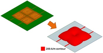
In order to create a larger charging platform, more than two coils need to be placed in the array. When four-square coils are placed in an array configuration, there is an area in the center of the array where the magnetic field cancels out, as shown in Fig. 7. Therefore, it is more practical for a charging array to use hexagonal coils.
Magnetic field for an array of four transmitter coils.

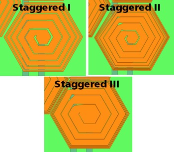
New staggered coils were constructed, as shown in Fig. 8, with a hexagonal profile. The coils have conductor widths of 1, 2, 3, 4, 5 and 6 mm for staggered I. Staggered II has conductor widths of 0.5, 0.5, 0.5, 2, 3, 4 and 5 mm. Staggered III has conductor widths of 0.5, 0.5, 0.5, 4, 4, 6 and 6 mm. In this case, the receive coil remains square and is not staggered but has approximately the same area as one transmitter coil, in order to examine a realistic scenario where the receiver coil and charging platform have not been optimized for each other.
Staggered hexagonal coils.

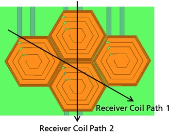
Two paths were simulated for the receiver coils to cross an array of four hexagonal coils. The first route crosses through the middle of the coils and the other route crosses over the edges, including the corner where three coils meet. The paths are shown in Fig. 9.
Crossing paths of the receiver coils.

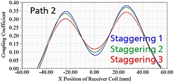
One sees in Fig. 10 that the amount that the hexagon is staggered changes the homogeneity of the magnetic field, but there is still a strong dependence on the position of the receiver coil. That being said, one can increase the minimum coupling coefficient by more than 50%.
Coupling coefficient over Path 2 for three different hexagonal coil geometries for a 5 mm coil separation distance.

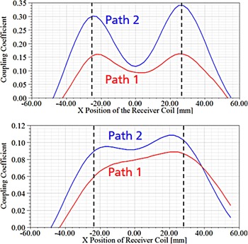
When we compare the two different paths, at different distances, in Fig. 11, we can also see that the minimums remain relatively close to each other. The coupling coefficient dips to 0.1 at a minimum, at 5 mm separation distances, and vary between the two paths by about 30%. The maximum coupling coefficients vary by more than 100%; however, the maximum is only achieved when the receiver and transmitter coils are exactly aligned. When the distance between the transmitter and receiver is increased to 20 mm, the coupling coefficient becomes much more homogeneous, varying from approximately 0.07 to 0.11 across the region where the receiver coil lies completely on top of the charging platform, and decaying slowly as it is shifted off.
Comparison of the coupling coefficients of two receiver coil paths at 5 mm separation distance (top) and 20 mm (bottom).

VI. MEASUREMENT RESULTS
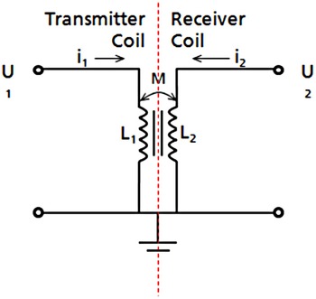
To measure the coupling coefficients, the input inductance of the transmitter coils was measured twice with the receiver coil at the given position. It was measured once with a short circuit at the receiver coil output and again with an open circuit at the receiver coil output. One can then use equations (1)–(7), based on Fig. 12, to calculate the mutual inductance and the coupling coefficient of the two coils.
Transmitter and receiver coil.

We begin by using Kirchoff's voltage law for both the transmitter and receiver coil sides, resulting equation (1) (transmitter side) and equation (2) (receiver side).
 $${U_1} = j\omega {L_1}{i_1} + j\omega M{i_2},$$
 $${U_2} = j\omega {L_2}{i_2} + j\omega M{i_1}.$$
Then, when the receiver is open-circuited, we can assume that no current flows on the receiver side, equation (3). Then, equation (2) can be simplified to equation (4):
 $${i_2}\, = \,0,$$
 $${U_2}\, = \,j\omega {L_1}{i_1}.$$
Oppositely, when the receiver is short-circuited, equation (5), then equation (2) is simplified to equation (6):
 $${U_2}\, = \,0,$$
 $$j\omega {L_1}{i_1}\, = \, - i\omega M{i_2}.$$
We can solve equations (6) and (4) simultaneously:
 $${Z_{Meas}} = j\omega {L_1}\left( {{L_1} - \displaystyle{{{M^2}} \over {{L_2}}}} \right).$$
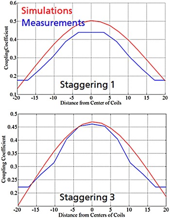
This allows us to determine the coupling coefficient from impedance measurements at the coil inputs. The measurements and the simulations show an excellent correlation, as shown in Fig. 13.
Correlation between measurements and simulations for the coupling coefficient of a receiver and transmitter coil with a separation distance of 5 mm.

VII. CONCLUSIONS
Based on simulation data, validated by measurements, it has been shown that a transmission coefficient can be achieved that varies by approximately 50% from the average value at a separation distance of 5 mm and 10% at a separation distance of 20 mm. Although the transmission coefficient is not as homogeneous as other published research, the receiver coil is not limited to being larger than the transmitter coil. The approach could be used to achieve a homogeneous charging platform for use with arbitrary-sized receiver coils, for example different consumer products on the same platform. The approach can also be used when the receiver coil must be contained in a small housing, medical devices, and implants, for example.
ACKNOWLEDGEMENTS
This research was supported by the German Federal Ministry for Economic Affairs and Energy, the Zentralverband Elektrotechnik- und Elektronikindustrie e.V. (ZVEI) and the German Federation of Industrial Research Associations (AIF).
 Brian Curran received his B.S. in electrical engineering from the University of Rochester, New York, his M.S. from the University of Kassel, Germany and his doctor of engineering from the Technical University of Berlin. He has worked at the Fraunhofer Institute for Reliability and Microintegration since 2008. His research includes signal and power integrity, antenna design and integration and electromagnetic compatibility.