I. INTRODUCTION AND MOTIVATION
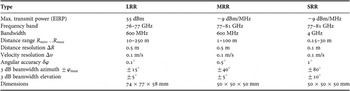
Radar sensors detecting the position and speed of objects around a car have become a cornerstone of modern driver assistance systems. Available sensors nowadays often operate in the 77 GHz band and demonstrate long-range operation of up to 250 m distance for accurate distance, velocity, and angle information about remote objects. With the vision of “360° Surround Automotive Radar” [Reference Lucas1], a safety belt based on radar sensors is coming into sight. This requires sensors operating in the long, mid, and short range. Table 1 shows typical sensor parameters envisioned, based on the different distance ranges.
Sensor types overview (LRR, MRR, and SRR).

Increasing the operation frequency means operating at shorter wavelengths, allowing either smaller antenna dimensions or a larger electrical aperture at the same mechanical dimensions. A key performance parameter that benefits from a larger aperture is the angular resolution and the associated angular accuracy. The angular resolution Δφ denotes the physical separability of two distinct objects, whereas the angular accuracy δφ describes the accuracy of the angle measurement based on wavelength, λ, aperture diameter d and signal-to-noise ratio, S/N [Reference Hasch, Topak, Schnabel, Zwick, Weigel and Waldschmidt2].
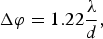 $$\Delta {\rm \varphi}=1.22\displaystyle{\lambda \over d}\comma \;$$
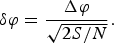 $${\rm \delta \varphi}=\displaystyle{{\Delta \rm \varphi } \over {\sqrt {2S/N} }}.$$
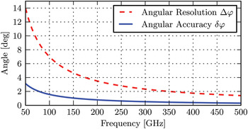
Figure 1 shows the frequency dependence of Δφ and δφ for an aperture d = 30 mm and an S/N of 10 dB. At 77 GHz these values are 9° and 4.6°, respectively. By doubling the frequency, the angular resolution and accuracy can be improved by a factor of two, to 4.5° and 2.3°. Alternatively, the antenna size can be reduced if the performance of the antenna system at lower frequencies is sufficient, potentially allowing a smaller size factor of the radar sensor.
Angular resolution and accuracy as a function of frequency.

II. INVESTIGATION OF BOUNDARY CONDITIONS
Considering the increase of the operation frequency of an established radar system calls for investigating important aspects like the availability of suitable materials, the influence of weather conditions and humidity or the radar cross-section of targets beyond 100 GHz.
Various standard radome materials have been tested with a broadband transmission setup using a vector network analyzer (VNA) with frequency converters from 75 to 325 GHz and with an additional hemispheric resonator at 77 GHz. From the measured S-parameters the relative permittivity and dielectric loss tangent can be extracted. Exemplary measurement results are shown in Table 2. In the tested frequency range, various automotive standard polymers show similar dielectric behavior making them suitable as radome material even at higher frequencies.
Relative permittivity and dielectric loss tangent of standard radome polymers.

Using the described transmission setup, dry and humidified materials have been compared to determine the attenuation of water deposits. A mean attenuation of 1.5 dB with a variance of ±1 dB has been measured in the focused frequency range (110–170 GHz), stating that water deposition on a radome has minor influence on the realization of radar in this frequency range.
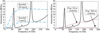
Using the data base from the International Telecommunication Union the attenuation of clear atmosphere, rain, and fog has been analyzed. In both the diagrams in Fig. 2, the black line approximates a standard atmospheric attenuation in European latitudes. Additionally, the attenuations of two different levels of rainfall (left) and the attenuation caused by fog at two different visibilities (right) can be seen. It is obvious that heavy rain particularly causes high attenuation above 100 GHz. However, this behavior is not a limiting factor, at least for a short- or a mid-range radar. Estimating a worst-case scenario at 150 GHz, the attenuations of warm, moist air (5 dB/km), heavy rain (30 mm/h, 14 dB/km), and dense fog (50 m visibility, 4 dB/km) sum to a total attenuation of 23 dB/km, respectively, to an only moderate two-way attenuation of 4.6 dB for a target in a distance of 100 m.
Attenuation of clear atmosphere, rainfall, and fog in the frequency range 0–300 GHz.

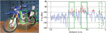
In an anechoic chamber (8 × 5 × 4 m), various targets have been analyzed concerning their radar cross-section (RCS) in WR06-band by using a quasi-monostatic measurement setup (VNA, frequency converters, and antennas). The antennas have been designed for achieving a beamwidth in the region of the target dimensions at a distance of 3.5 m (far-field conditions). The results of a motorcycle on a turn-table illustrated in the left-side picture of Fig. 3 are discussed here.
Time-domain signal of the reflected power of a motorcycle in WR06-band.

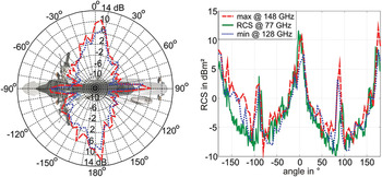
By a time-domain transformation of the S-parameters (110–170 GHz), shown in the right side diagram, significant reflections can be seen at different distances. From the local appearance of reflections the target dimensions can nearly be estimated showing the potential of larger bandwidth for improved target identification. The calculation of a definite RCS requires a definite distance, determined by averaging all distances showing a significant reflection and multiplying them with a power-related factor. The RCS at different angles of view is given in Fig. 4. The dashed line corresponds to the maximum, the dotted line to the minimum RCS in WR06-band appearing at 148 and 128 GHz. A comparison to the RCS at 77 GHz can be seen in the right side diagram. Within the tested frequency range minima and maxima appear due to constructive and destructive interferences. Increasing the frequency means no general change of the RCS, but the larger detection bandwidth offers possibilities for signature identification.
RCS of a motorcycle at different angles of view at two frequencies in WR06-band (left) and in comparison with 77 GHz (right).

III. ACTIVE CIRCUITS TECHNOLOGY
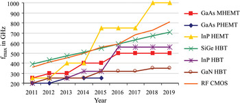
Silicon-based solutions for 77 GHz radar sensors have become commercially available in bipolar SiGe technology from different companies and even first CMOS implementations have been demonstrated by research groups [Reference Hasch, Topak, Schnabel, Zwick, Weigel and Waldschmidt2]. With a maximum oscillation frequency now exceeding 300 GHz for silicon-based technologies, shown in the ITRS roadmap in Fig. 5, transceiver circuits above 100 GHz have become feasible [3]. Successful designs of silicon-based radar transceivers above 100 GHz have been published by a number of groups (e.g. [Reference Pfeiffer4]).
ITRS roadmap.

The availability of silicon technology for >100 GHz circuits also allows higher integration as previously known, adding complex circuit blocks such as modulation, calibration, and baseband processing directly to the transceiver. Also, faster transistors not only allow higher operation frequencies, but they also lead to circuits with lower noise and less power consumption.
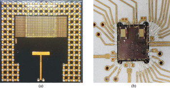
Another crucial topic is packaging the millimeter-wave front-end circuits. Solutions for the standard SMD soldering are available nowadays at 77 GHz, with more advanced solutions such as “Antenna on Chip” and “Antenna in Package” shown in Fig. 6 are currently being actively researched [Reference Hasch, Topak, Schnabel, Zwick, Weigel and Waldschmidt2]. These approaches are scalable to higher frequencies, as the antenna dimensions can get smaller.
77 GHz Transceivers with integrated antennas. (a) Antenna in package, (b) Antenna on chip.

IV. SYSTEM SIMULATION
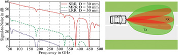
To evaluate an upper frequency boundary for the feasibility of automotive radar sensors, simple system simulations have been carried out. They are based on the parameters of Table 1 and the basic radar equation, and they simply calculate the signal-to-noise ratio in the receiver of a radar sensor for a remote object with a typical RCS of σ T = 10 m2:
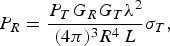 $$P_R=\displaystyle{{P_T G_R G_T \lambda ^2 } \over {\lpar 4{\rm \pi} \rpar ^3 R^4\, L}}\sigma _T\comma \;$$
 $$P_N=kT \cdot NF \cdot B\comma \;$$
 $${\rm S/N}=\displaystyle{{P_R } \over {P_N }}.$$
To model the performance reduction of the radar system with increasing frequency, additional losses were taken into account. For transmit and receive antennas, the efficiency of each antenna is reduced by  $ 1/ \sqrt f $, leading to a penalty of 6 dB at 500 GHz compared with 77 GHz. To take into account the active circuit performance, the noise figure (NF) was modeled after the noise behavior of a bipolar transistor
 $F_{min} \approx 1+\displaystyle{f \over {f_T }}\sqrt {2g_m \lpar r_B r_E \rpar } $, leading to an increase in the NF from 13 dB at 77 GHz to 33 dB at 500 GHz, assuming no change in transistor technology. The results shown in Fig. 7 are calculated for a bistatic radar configuration, i.e. having different transmit and receive antenna beam patterns. The transmit antenna is designed to illuminate the scene with a gain of G T = 21, 17, and 11 dBi at 77 GHz for long-range radar (LRR), mid-range radar (MRR), and short-range radar (SRR) operations, respectively, corresponding to the different beamwidths of Table 1. The receive antenna gain G R is determined by aperture size and frequency-dependent loss, and varies between 24–35 dBi (D = 30 mm) and 28–40 dBi (D = 50 mm). The transmit power is fixed to 10 dBm and the receiver bandwidth B is 500 Hz. A threshold of 10 dB S/N is required to assure operation, so it can be seen from Fig. 7, that for long-range operation the maximum frequency is about 170 GHz. For MRR/SRR, frequencies above 300 GHz are still feasible. For the given transmit power, LRR operation is only feasible up to 150 GHz. It can be extended to higher frequencies by using higher-gain antennas or increasing the transmit power. However, the atmospheric attenuation peak at 180 GHz will continue to play a significant role.
System simulation results for a bistatic radar configuration.

V. FREQUENCY REGULATION
To enable the commercial use of any frequency band, a corresponding frequency regulation – tailored to the specific application – is required. Technical parameters established by regulation typically include centre frequency, bandwidth, and maximum allowed radiated power and duty cycle. It can also deny certain usage or impose deployment restrictions.
An important prerequisite to start a regulatory effort is the understanding of technical requirements and the application scenario. Based on the results derived in this paper, the basic requirements for the frequency regulation of automotive radar sensors above 100 GHz are:
• Operation in the frequency range of 140–300 GHz, required to at least double the angular resolution.
• A bandwidth of 4 GHz – as in the existing 77–81 GHz regulation – to allow broadband modulation and frequency separation of multiple sensors.
• A maximum transmit power of at least +40 dBm equivalent isotropically radiated power (EIRP) to enable long-range operation up to 200 GHz.
• Allow 100% duty cycle without mitigation requirements concerning other radio services. This is required for reliable sensor operation; otherwise the sensor might be inoperable in critical situations.
• Mounting is allowed at any position around the car to enable the vision of 360°.
Such a regulation would make it feasible to develop new radar sensors for the next decade with an expected market penetration of several million devices.
VI. ANTENNA CONCEPT FOR A 150 GHz RADAR SENSOR
With the following very compact antenna realization on a low-cost radiofrequency (RF) laminate an attractive alternative to antenna on chip solutions especially for higher frequencies is presented. The design goal was to realize an antenna fulfilling the RF demands (system bandwidth >1 GHz, azimuth detection range of ±40° with an angular resolution of 5°, 3 dB elevation beamwidth (one way) of 9°, sidelobe level (SLL) of 20 dB) as well as the limited space requirements.
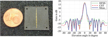
A symmetric serial patch antenna depicted in Fig. 8 (left) with a center patch feed by a coupling slot in the ground plane has been designed and optimized with CST Microwave Studio and Ansoft HFSS. Measurements state a return loss <−17 dB and a 10 dB bandwidth of >8 GHz. A comparison of simulations and measurement results concerning the antenna gain in elevation is shown in the right diagram in Fig. 8. A gain of 16.5 dB, a SLL of −19.6 dB and a 3 dB beamwidth of 7.8° have been attained after optimization.
Photograph of patch antenna (left) and elevation gain compared with simulations (right).

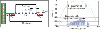
According to the lateral detection range a 3 dB azimuth beamwidth of ±40° being suited for digital beam forming has been measured. As shown in Fig. 9, with a sparse periodic array consisting of 6 Tx and 7 Rx and using a modified power distribution [Reference Schuler, Younis, Lenz and Wiesbeck5], an angular resolution of 5° and SLL of −40 dB can be obtained at the maximum azimuth detection angle of 40°.
SPA antenna constellation (left) and antenna characteristics (right).

As demonstrated, a sufficient angular resolution and a high SLL can be realized with antenna dimensions of 30 × 30 mm. Considering an antenna with current mechanical sensor dimensions of about 50 × 50 mm, but now operating in the frequency range of 140–300 GHz an even higher resolution can be achieved. A sufficient high resolution is still a drawback of current 79 GHz systems but essential for detecting weakly reflecting objects in presence of a nearby strong reflector. Actually, the increasing antenna performance at higher frequencies enables a new generation of imaging systems in cars not only detecting but also identifying the surrounding targets. Moreover, the thin bendable RF laminate is suited for embedding antennas within a multi-layered car body panel [Reference Kilian and Schmidt6]. Hence, the arrangement of miniaturized antennas in cars will be more flexible, being in line with the vision of “360° Surround Automotive Radar”.
VII. CONCLUSION
The feasibility of automotive radar at frequencies beyond 100 GHz to improve angular resolution has been investigated. An increase up to 140–300 GHz has proven to be feasible based on the performed investigation of dielectric properties of material, attenuation of the atmosphere, RCS behavior, available silicon technology, as well as antenna and packaging concepts. A miniaturized antenna at 150 GHz has been presented showing a comparable performance to current 77 GHz systems and indicating the possibilities of high-resolution radar at higher operating frequencies even allowing for imaging applications.
ACKNOWLEDGEMENTS
This work has been supported in part by the German Federal Ministry of Education and Research (BMBF) under contract no. 13N9820–13N9824 “Radar on Chip for Cars” (RoCC).
 Mike Köhler received his Dipl.-Ing. in 2008 from the University of Erlangen-Nuremberg. Since that time he has been working at the Institute of Microwaves and Photonics with research focus at mm-wave technology beyond 100 GHz.
 Jürgen Hasch received his Ph.D. in 2007 from the Institute of Semiconductor Technology at the University of Stuttgart. He is a senior RF expert at the Robert Bosch GmbH in Stuttgart. His main interests are ultra-wideband and millimeter-wave sensors.
 Hans Ludwig Blöcher Hans-Ludwig Bloecher received the Dipl.-Ing. degree in Communication Engineering and the Dr.-Ing. degree in RF- and Microwave Engineering from the University of Siegen, Germany, respectively. At Daimler AG Group Research and Advanced Engineering, Ulm, he is in-charge for next generation automotive radar technology.
 Lorenz-Peter Schmidt received the Diploma and Ph.D. degrees from the Technical University of Aachen in 1974 and 1979, respectively. In 1979, he was a Post-Doc. at the University of Texas in Austin. From 1980 to 1998, he was with AEG-Telefunken, Ulm, Germany (later DASA, now CASSIDIAN), where he became the head of the Advanced Microwave and Millimeter-Wave Development Department. Since 1998, he has been a Full Professor and the Head of the Institute of Microwaves and Photonics at the University of Erlangen-Nuremberg. His main research interests are in the field of mmW and THz components and antenna technologies, as well as active and passive imaging systems, laser technology, and microwave/photonic interaction.