1. Introduction
Garrett (Reference Garrett1970) presented a solution to the diffraction problem of a bottomless harbour that is circumferentially closed and argued that any realistic model of a real floating harbour must include the effects of the harbour shape, thickness and opening (harbour entrance), but the shape would not cause any qualitative differences and the thickness had negligible effects. He construed that ‘the effect of the harbour entrance is less obvious’. In this work, we will attempt to shed some light on exactly this last point. We will tackle the problem numerically using a boundary-integral approach and provide an understanding of the results obtained.
The proposal to build a floating harbour or intermediate transport station close to the Brazilian coast (de Oliveira et al. Reference de Oliveira, Vilameá, Figueiredo and Malta2013) as well as the emerging Portunus Project, which proposes to construct floating harbours off the coasts of the USA (Wampler Reference Wampler2010), require an understanding of the consequences of having an open-shaped body in the ocean, because the harbour will inevitably be an open body. Furthermore, the desire to design more cost-effective ocean structures motivates engineers to examine unconventional designs for these structures. One instant suggestion is to use open columns to support platforms and other facilities. This requires a thorough understanding of the changes that occur when these columns are opened. Typically, these problems are three-dimensional and computationally expensive. The computational effort is significantly reduced by assuming that the bodies have zero thickness.
The study of a wave field interacting with such thin structures is worth while, as these often appear in designs. Stiffeners, plates and shells are important examples used in marine design. The numerical treatment of these components by standard means, such as the boundary-integral method, is expected to be troublesome. The usual situation is that the numerical problem becomes ill-conditioned as the thickness of the body decreases. This is because two opposite points of the body surface tend to carry the same information in the limit of vanishing thickness. It is more natural then to consider the potential jump across the body surface instead. This reduces the number of problem unknowns to at least a half, which is a significant reduction for three-dimensional problems.
It follows from the boundary-integral formulation that the potential field over a zero-thickness shell is represented by a double-layer sheet. The application of boundary conditions then leads to a hypersingular integral that needs to be computed carefully (Krishnasamy et al. Reference Krishnasamy, Schmerr, Rudolphi and Rizzo1990; Parsons & Martin Reference Parsons and Martin1992). Such a treatment is also a good approximation to bodies of the same shape having a finite but small thickness (Mavrakos Reference Mavrakos1988). This method was originally used in solid mechanics for crack problems by Martin & Rizzo (Reference Martin and Rizzo1989) and was later used for water–wave problems to model the scattering (Parsons & Martin Reference Parsons and Martin1992, Reference Parsons and Martin1994) and radiation (Martin & Farina Reference Martin and Farina1997; Farina & Martin Reference Farina and Martin1998) of water waves from flat or curved plates and disks. These last references used a novel method to deal with the hypersingularity. The potential jump over the body surface was represented in terms of Chebyshev basis functions with the proper weights so that the hypersingular integral could be evaluated analytically over flat surfaces. The same method could be used for different geometries if the integrand is written as the sum of singular and regular terms. The integral of the singular part is then treated analytically and the correction terms are integrated numerically. This is the case in Renzi & Dias (Reference Renzi and Dias2012) in which a wave energy converter, modelled as a thin vertical plate, was considered. This procedure also has the advantage of considering the square-root singular behaviour near the body edges explicitly. The problem is that the series expansion of the integrand has to be valid over all the body surface, which may require several terms in the series expansion, especially as the body shape becomes more complicated. Integration over the whole surface is also required to compute each influence coefficient of the linear system. Given that calculating these coefficients requires the bulk of the computational effort, it is more desirable to find a less expensive method. The procedure we present here depends on a set of compact basis functions and does not require any series expansion over the entire body surface. The method is found to be very stable and well conditioned. Note that the hypersingular integral can be avoided altogether by regularization (Krishnasamy et al. Reference Krishnasamy, Schmerr, Rudolphi and Rizzo1990). This involves the use of Stokes’s theorem to reduce the order of the singularity, but usually requires some additional work for the evaluation of tangential derivatives of the unknown potential, which presents another numerical challenge that cannot be easily handled in practice.
In this paper, we treat the singularity directly by Taylor-expanding the integrand about the singular point. This is the approach for the case of a truncated circular cylinder in Yeung & Hariri Nokob (Reference Yeung and Hariri Nokob2013). In this work, the original field equation is transformed into a set of Helmholtz equations in two dimensions after the potential is expanded in terms of the natural vertical modes. This procedure was used in Renzi & Dias (Reference Renzi and Dias2012) to model a flap-type wave energy converter. This decomposition, which only applies for bottom-mounted cylinders, is very convenient from a computational standpoint, as the numerical procedure is simplified and the computation time is significantly reduced.
Our solution method is applied to model incident-wave flow over vertical cylinders of any cross-sectional shapes. This conveniently allows us to model open shells and to study the wave loads on these bodies subject to time-harmonic incident waves or arising because of the motion of the bodies themselves in surge, sway, roll, pitch and yaw directions. We assume that these motions are possible even though the cylinders extend to the ocean floor. That means that proper supports are used at the bottom or the results here are approximations to finite-draught bodies whose height is comparable to the water depth. This is a good approximation in general, especially in deeper water, where most activity is confined near the free surface. The authors’ previous works on this subject include Hariri Nokob & Yeung (Reference Hariri Nokob and Yeung2014a ,Reference Hariri Nokob and Yeung b ). Here, a higher-order method based on the modified Overhauser elements is used to solve the hypersingular problem. The results for an open shell are then analysed in some detail.
We also note that the hypersingular integral-equation formulation is used to avoid non-uniqueness problems (irregular frequencies) associated with floating solid bodies (Burton & Miller Reference Burton and Miller1971; Lee & Sclavounos Reference Lee and Sclavounos1989). The combination of the hypersingular integral equation with the less singular equation is well posed for all frequencies. The open thin shells considered herein do not suffer from those problems because no internal potential (inside the thin bodies) exists but the procedure presented here is useful in those situations as well.
The following sections start by presenting the problem formulation and method of solution. Then, radiation and diffraction results for open circular, elliptical and square-shaped shells are presented and discussed. The free-surface elevations for some particular geometries are also presented.
2. Computational theory
2.1. Problem formulation
We assume linear water wave potential theory. All potentials
 ${\it\Phi}$
are considered harmonic in time with frequency
 ${\it\omega}$
such that
 ${\it\Phi}(x,y,z,t)=\text{Re}\{{\it\phi}(x,y,z)\text{e}^{-\text{i}{\it\omega}t}\}$
. These potentials are normalized as
 ${\it\phi}^{R}=\overline{{\it\phi}}^{R}/a^{l}U$
and
 ${\it\phi}^{S}=\overline{{\it\phi}}^{S}/{\it\eta}_{0}\sqrt{ga}$
for any of the radiation and scattering potentials, respectively. The terms with an overbar are always dimensional,
 $a$
is a characteristic length of the body,
 $g$
is the acceleration of gravity and
 ${\it\eta}_{0}$
is the incident-wave amplitude. The constant
 $U$
is the amplitude of the translation and rotation forced motions and the integer
 $l$
is 1 for surge and sway and is 2 for roll, pitch and yaw. These motions will be denoted by the integers
 $p=1,2,4,5,6$
, respectively, and we use
 $p=0,7$
for the incident and diffracted potentials. The corresponding potential for these different motions is denoted by
 ${\it\phi}^{p}$
. In addition, the water depth is finite and given by
 $h$
.
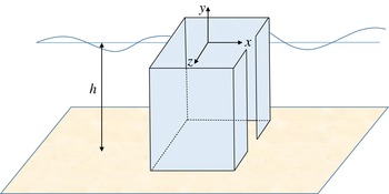
Schematic diagram of a square-shaped open shell.

Let the coordinate system be fixed on the calm free surface with the
 $y$
axis pointing upwards (figure 1). We use the characteristic length
 $a$
to non-dimensionalize all length parameters and wavenumbers in this work. The problem is then the classical water wave formulation given by
 $$\begin{eqnarray}\displaystyle & {\rm\nabla}^{2}{\it\phi}^{p}=0, & \displaystyle\end{eqnarray}$$
 $$\begin{eqnarray}\displaystyle & \displaystyle \frac{\partial {\it\phi}^{p}}{\partial y}-{\it\nu}{\it\phi}^{p}=0,\quad {\it\nu}=\frac{{\it\omega}^{2}a}{g},\quad \text{for}~y=0, & \displaystyle\end{eqnarray}$$
 $$\begin{eqnarray}\displaystyle & \displaystyle \frac{\partial {\it\phi}^{p}}{\partial y}=0,\quad \text{for}~y=-h. & \displaystyle\end{eqnarray}$$
 $\boldsymbol{n}=[n_{1},0,n_{2}]$
be the normal vector pointing out of the body. Then the kinematic condition on the body surface applies as:
 $$\begin{eqnarray}\frac{\partial {\it\phi}^{p}}{\partial n}=\left\{\begin{array}{@{}ll@{}}n_{p},\quad & (\,p=1,2),\\ (y+h)n_{p-3},\quad & (\,p=4,5),\\ zn_{1}-xn_{2},\quad & (\,p=6),\\ \displaystyle -\frac{\partial {\it\phi}^{0}}{\partial n},\quad & (\,p=7).\end{array}\right.\end{eqnarray}$$
We assumed that the rolling and pitching axes pass through the origin projection on the ocean floor. A radiation condition that dictates outgoing waves is also required. Now we can introduce the decomposition
 $$\begin{eqnarray}\displaystyle {\it\phi}^{p}(x,y,z)=\mathop{\sum }_{n=0}^{\infty }{\it\varphi}_{n}^{p}(x,z)Y_{n}(y), & & \displaystyle\end{eqnarray}$$
 $$\begin{eqnarray}\displaystyle Y_{n}(y)=\frac{\cosh ({\it\kappa}_{n}(y+h))}{M_{n}},\quad M_{n}=\sqrt{\frac{\sinh (2{\it\kappa}_{n}h)}{4{\it\kappa}_{n}}+\frac{h}{2}}, & & \displaystyle\end{eqnarray}$$
where the
 $M_{n}$
are scale factors to make the
 $Y_{n}$
an orthonormal set. The functions
 ${\it\varphi}_{n}^{p}$
are unknown modal potentials in the horizontal plane, and
 ${\it\kappa}_{n}$
are real (
 $n=0$
) and imaginary (
 $n>0$
) wavenumbers that satisfy the usual dispersion relation,
 ${\it\kappa}_{n}\tanh ({\it\kappa}_{n}h)={\it\nu}$
. The functions
 $Y_{n}(y)$
satisfy the conditions (2.2) and (2.3), effectively removing any depth dependence. The incident potential is given and can be decomposed in the same manner as
 $$\begin{eqnarray}\displaystyle & {\it\phi}^{0}(x,y,z)={\it\varphi}_{0}^{0}(x,z)Y_{0}(y), & \displaystyle\end{eqnarray}$$
 $$\begin{eqnarray}\displaystyle & \displaystyle {\it\varphi}_{0}^{0}=\frac{\text{e}^{\text{i}{\it\kappa}_{0}(x\cos {\it\beta}+z\sin {\it\beta})}}{\text{i}\sqrt{{\it\nu}}Y_{0}(0)}, & \displaystyle\end{eqnarray}$$
 ${\it\beta}$
is the incident-wave direction (figure 2). The problem thus reduces to:
 $$\begin{eqnarray}\displaystyle & ({\rm\nabla}^{2}+{\it\kappa}_{n}^{2}){\it\varphi}_{n}^{p}=0, & \displaystyle\end{eqnarray}$$
 $$\begin{eqnarray}\displaystyle & \displaystyle \frac{\partial {\it\varphi}_{n}^{p}}{\partial n}=\left\{\begin{array}{@{}ll@{}}\displaystyle n_{p}\frac{\sinh ({\it\kappa}_{n}h)}{{\it\kappa}_{n}M_{n}},\quad & (\,p=1,2),\\ \displaystyle \frac{n_{p-3}}{{\it\kappa}_{n}^{2}M_{n}}({\it\kappa}_{n}h\sinh ({\it\kappa}_{n}h)-\cosh ({\it\kappa}_{n}h)+1),\quad & (\,p=4,5),\\ \displaystyle (zn_{1}-xn_{2})\frac{\sinh ({\it\kappa}_{n}h)}{{\it\kappa}_{n}M_{n}},\quad & (\,p=6),\\ \displaystyle -\frac{\partial {\it\varphi}_{0}^{0}}{\partial n}{\it\delta}_{0n},\quad & (\,p=7).\end{array}\right. & \displaystyle\end{eqnarray}$$
 $Y_{n}$
are orthogonal over the water depth. Equations (2.9) and (2.10) will be solved as an integral equation using the boundary element method. The potential
 ${\it\varphi}_{n}^{p}$
is thus represented by a normal dipole sheet and then (2.10) is applied (Parsons & Martin Reference Parsons and Martin1992):
 $$\begin{eqnarray}\frac{\partial {\it\varphi}_{n}^{p}}{\partial n_{P}}=\int _{C}[{\it\varphi}_{n}^{p}]\frac{\partial ^{2}G_{n}}{\partial n_{P}\partial n_{Q}}\text{d}s,\end{eqnarray}$$
where
 $[{\it\varphi}_{n}^{p}]$
is the potential jump across the body,
 $P(x,z)$
and
 $Q({\it\xi},{\it\zeta})$
are collocation and integration points, respectively (see e.g. Yeung Reference Yeung1982),
 $C$
is one side of the body surface and
 $G_{n}$
is the fundamental solution of the corresponding Helmholtz equation and is given by (Burton & Miller Reference Burton and Miller1971):
 $$\begin{eqnarray}\displaystyle & \displaystyle G_{n}=-\frac{\text{i}}{4}\text{H}_{0}({\it\kappa}_{n}R), & \displaystyle\end{eqnarray}$$
 $$\begin{eqnarray}\displaystyle & \displaystyle R=|PQ|=\sqrt{(x-{\it\xi})^{2}+(z-{\it\zeta})^{2}}. & \displaystyle\end{eqnarray}$$
 $\text{H}_{0}$
is the Hankel function of the first kind and order zero. In general, an additional term needs to be added to the left-hand side of (2.11) to account for the fact that the kernel is hypersingular (see Guiggiani Reference Guiggiani1995). However, the additional term is not needed in this case because we will use straight panels with zero curvature to discretize the boundary. More care should be taken for higher-order elements.
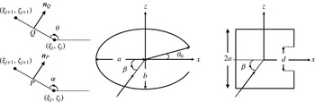
Schematic of one panel showing points
 $Q$
and
 $P$
and the cross-sectional shapes of elliptical and square-shaped bodies. The incident-wave direction, of angle
 ${\it\beta}$
, is also shown.

Using the fact that
 $\boldsymbol{n}_{P}=[\sin ({\it\alpha}),-\!\cos ({\it\alpha})]$
and
 $\boldsymbol{n}_{Q}=[\sin ({\it\theta}),-\!\cos ({\it\theta})]$
, where
 ${\it\alpha}$
and
 ${\it\theta}$
are the slope angles of the body curve in the horizontal plane (defined in figure 2), we have
 $$\begin{eqnarray}\displaystyle \frac{\partial ^{2}G_{n}}{\partial n_{P}\partial n_{Q}} & = & \displaystyle \frac{\text{i}{\it\kappa}_{n}}{4R^{2}}\left(\frac{2\text{H}_{1}({\it\kappa}_{n}R)}{R}-{\it\kappa}_{n}\text{H}_{0}({\it\kappa}_{n}R)\right)\nonumber\\ \displaystyle & & \displaystyle \times [({\it\xi}-x)^{2}\sin ({\it\alpha})\sin ({\it\theta})+({\it\zeta}-z)^{2}\cos ({\it\alpha})\cos ({\it\theta})\nonumber\\ \displaystyle & & \displaystyle -\,({\it\xi}-x)({\it\zeta}-z)\sin ({\it\theta}+{\it\alpha})\!]-\frac{\text{i}{\it\kappa}_{n}}{4R}\text{H}_{1}({\it\kappa}_{n}R)\cos ({\it\theta}-{\it\alpha}).\end{eqnarray}$$
2.2. Numerical integration and solution procedure
The body contour is divided into
 $N$
flat panels
 $C_{j}[({\it\xi}_{j},{\it\zeta}_{j}),({\it\xi}_{j+1},{\it\zeta}_{j+1})]$
as in figure 2. Collocation inside the panels is easy and does not require higher-order interpolating basis functions, but that leads to non-conforming elements, which results in a lower accuracy of the formulation as well as a dependence on the position of the collocation points (see Manolis & Banerjee (Reference Manolis and Banerjee1986) for more information). It is thus more natural and desirable to collocate at the edges of the panels. This ensures that the boundary conditions are met at the exact positions of the original problem. Because the kernel of the integral in (2.11) is hypersingular, this requires a density distribution that at least belongs to
 $C^{1,{\it\alpha}}$
, the space of functions with Hölder-continuous first derivatives (Martin & Rizzo Reference Martin and Rizzo1989). However, this requirement can be loosened as indicated in Martin & Rizzo (Reference Martin and Rizzo1996). In fact, we will use the concepts in this last reference as explained in appendix A. Nonetheless, to obtain a high-order method, we choose to use the modified cubic Overhauser polynomial elements to represent the potential jump distribution. These elements have a continuous derivative at the edges of the panels and the interesting property of being locally independent of each other. That is, any local errors will not propagate across the mesh as in the case of other functions. They also do not require the evaluation of derivatives at the edges, as continuity of the derivatives is guaranteed by the structure of the elements themselves. This makes them simple to use. Furthermore, several authors have shown the superiority of these elements in certain aspects such as stability. Short reviews on these elements can be found in Sladek & Sladek (Reference Sladek and Sladek1998) and Hadavinia, Travis & Fenner (Reference Hadavinia, Travis and Fenner2000). The authors in this last reference note that the Overhauser elements suffer from errors when the mesh size is non-uniform. They develop a set of modified Overhauser elements that take the varying mesh into account and show their applicability to boundary element methods. We choose to adopt those last elements in this work.
We introduce a parameter
 $t$
that varies between 0 and 1 over some panel
 $C_{j}$
. Let
 $[{\it\varphi}]_{j}$
be the value of the density at the starting edge of the panel
 $C_{j}$
. If
 $C_{j}$
is not an end panel of the shell, then the density
 $[{\it\varphi}]$
over that panel is interpolated as
 $$\begin{eqnarray}\displaystyle & \displaystyle [{\it\varphi}]=\mathop{\sum }_{q=j-1}^{j+2}N_{q}(t)[{\it\varphi}]_{q}, & \displaystyle\end{eqnarray}$$
 $$\begin{eqnarray}\displaystyle & \displaystyle N_{q}(t)=\mathop{\sum }_{k=1}^{4}\unicode[STIX]{x1D623}_{qk}t^{k-1}. & \displaystyle\end{eqnarray}$$
 $N_{q}(t)$
are the Overhauser elements. These coefficients vary for each panel and are given by
 $$\begin{eqnarray}\displaystyle & & \displaystyle \unicode[STIX]{x1D623}_{qk}=\left[\begin{array}{@{}cccc@{}}0 & \displaystyle -\frac{(1-w_{1})^{2}}{w_{1}} & \displaystyle \frac{2(1-w_{1})^{2}}{w_{1}} & \displaystyle -\frac{(1-w_{1})^{2}}{w_{1}}\\ 1 & \displaystyle \frac{1-2w_{1}}{w_{1}} & \displaystyle \frac{w_{1}(2-w_{2})-2}{w_{1}} & \displaystyle \frac{w_{1}(w_{2}-1)+1}{w_{1}}\\ 0 & w_{1} & \displaystyle \frac{2(1-w_{1})-w_{2}(1-2w_{1})}{1-w_{2}} & \displaystyle \frac{w_{1}(1-w_{2})-1}{1-w_{2}}\\ 0 & 0 & \displaystyle -\frac{w_{2}^{2}}{1-w_{2}} & \displaystyle \frac{w_{2}^{2}}{1-w_{2}}\end{array}\right]\!,\nonumber\\ \displaystyle & & \displaystyle \quad w_{1}\equiv \frac{S_{j-1}}{S_{j}+S_{j-1}},\quad w_{2}\equiv \frac{S_{j}}{S_{j+1}+S_{j}},\end{eqnarray}$$
where
 $S_{j}$
is the length of
 $C_{j}$
. If the panel lies on either end of the shell, then quadratic Overhauser polynomials are sufficient to ensure continuity of the derivative at the inner edge of the panel. In that case, the coefficient matrix needs to be changed to
 $$\begin{eqnarray}\unicode[STIX]{x1D623}_{qk}=\left[\begin{array}{@{}cccc@{}}1 & -w-1 & w & 0\\ 0 & \displaystyle \frac{1}{1-w} & \displaystyle -\frac{w}{1-w} & 0\\ 0 & \displaystyle -\frac{w^{2}}{1-w} & \displaystyle \frac{w^{2}}{1-w} & 0\\ 0 & 0 & 0 & 0\end{array}\right]\!,\quad w\equiv \frac{S_{j}}{S_{j}+S_{j+1}},\end{eqnarray}$$
for a panel at the start of the sheet and to
 $$\begin{eqnarray}\unicode[STIX]{x1D623}_{qk}=\left[\begin{array}{@{}cccc@{}}0 & 0 & 0 & 0\\ 0 & \displaystyle -\frac{w^{2}}{1-w} & \displaystyle \frac{w^{2}}{1-w} & 0\\ 1 & \displaystyle \frac{2w-1}{1-w} & \displaystyle -\frac{w}{1-w} & 0\\ 0 & 1-w & w & 0\end{array}\right]\!,\quad w\equiv \frac{S_{j}}{S_{j}+S_{j-1}},\end{eqnarray}$$
for a panel at the end of a sheet. The same concept is used at corner points, where the potential jump is continuous but the derivatives can be unbounded. The two corner panels will be the start and end panels of their respective sheets. The evaluation of the integral in (2.11) then involves integrals of the form
 $$\begin{eqnarray}\int _{C_{j}}t^{k-1}\frac{\partial ^{2}G_{n}}{\partial n_{P}\partial n_{Q}}\text{d}s=\frac{1}{S_{j}^{k-1}}\int _{0}^{S_{j}}s^{k-1}\frac{\partial ^{2}G_{n}}{\partial n_{P}\partial n_{Q}}\text{d}s.\end{eqnarray}$$
These integrals are regular (evaluated by standard numerical quadrature) except when the collocation point lies on one of the edges of the panel. The treatment of this last case requires special care and is detailed in appendix A.
Once all influence coefficients are evaluated at the collocation points, we obtain a system of equations that is solved for the potential jumps across the panels at the collocation points. We only collocate at points connecting two panels. We also assume that the normal vector at the collocation point is the mean of the normal vectors of the two panels. The end points of the sheet are assumed to have zero potential jump, as the potential (and pressure) go back to being continuous in the body of the fluid. In fact, the jump in potential varies as
 $\sqrt{t}$
near
 $t=0$
for a panel on the starting edge of the sheet and as
 $\sqrt{1-t}$
near
 $t=1$
for a panel on the ending edge (Martin Reference Martin1991). Polynomials cannot adequately represent that type of end behaviour in general. However, by using a dense collection of panels near the edges, the effect will be very small, especially for the load computations, which are integrated quantities. More precise end behaviour could possibly be incorporated in the method in a manner similar to Martin & Rizzo (Reference Martin and Rizzo1989).
2.3. The wave loads and surface elevation
The wave loads on the body can be obtained by integrating the dynamic pressure over its surface. We define the dimensionless added inertia and damping coefficients as
 ${\it\mu}_{kp}=M_{kp}/{\it\rho}h\overline{A}a^{c}$
and
 ${\it\lambda}_{kp}=B_{kp}/{\it\rho}h\overline{A}a^{c}{\it\omega}$
, respectively. Here,
 ${\it\rho}$
is the water density,
 $c$
is an integer ranging between 0 and 2 chosen to make the expressions dimensionless and
 $\overline{A}$
is the surface area of the internal region. The excitation force from the diffraction problem is also normalized as
 $f_{k}=F_{k}/{\it\rho}{\it\eta}_{0}g\overline{A}a^{l-1}$
, where the integer
 $l$
was previously defined. The wave loads are then expressed by
 $$\begin{eqnarray}\displaystyle & \displaystyle {\it\mu}_{kp}+\text{i}{\it\lambda}_{kp}=\frac{1}{Ah}\int _{C}\int _{-h}^{0}[{\it\phi}^{p}]\frac{\partial {\it\phi}^{k}}{\partial n}\text{d}y\,\text{d}s, & \displaystyle\end{eqnarray}$$
 $$\begin{eqnarray}\displaystyle & \displaystyle f_{k}=-\frac{\text{i}\sqrt{{\it\nu}}}{A}\int _{C}\int _{-h}^{0}[{\it\phi}^{7}]\frac{\partial {\it\phi}^{k}}{\partial n}\text{d}y\,\text{d}s. & \displaystyle\end{eqnarray}$$
 $A=\overline{A}/a^{2}$
is the dimensionless area, which is
 ${\rm\pi}$
,
 ${\rm\pi}b$
and 4 for circular, elliptical and square shells, respectively. The normal gradient of the potential in these expressions was given in (2.4). Note that the incident wave does not contribute to the loads because the body has zero thickness. The integrals in these expressions are evaluated in appendix B. It is also useful to visualize the free-surface elevation over the wave field near the body. The expression for the elevation is obtained from the field potential through the integral equation and is given by
 $$\begin{eqnarray}\displaystyle & \displaystyle \frac{{\it\eta}^{S}}{{\it\eta}_{0}}=\text{e}^{\text{i}{\it\kappa}_{0}(x\cos {\it\beta}+z\sin {\it\beta})}+\text{i}\sqrt{{\it\nu}}Y_{0}(0)\int _{C}[{\it\varphi}_{0}^{7}]\frac{\partial G_{0}}{\partial n_{Q}}\text{d}s, & \displaystyle\end{eqnarray}$$
 $$\begin{eqnarray}\displaystyle & \displaystyle \frac{{\it\eta}^{p}}{U\sqrt{a/g}}=\text{i}\sqrt{{\it\nu}}\mathop{\sum }_{n=0}^{\infty }Y_{n}(0)\int _{C}[{\it\varphi}_{n}^{p}]\frac{\partial G_{n}}{\partial n_{Q}}\text{d}s, & \displaystyle\end{eqnarray}$$
 $$\begin{eqnarray}\displaystyle & \displaystyle \frac{\partial G_{n}}{\partial n_{Q}}=\frac{\text{i}{\it\kappa}_{n}\text{H}_{1}({\it\kappa}_{n}R)}{4R}[({\it\xi}-x)n_{{\it\xi}}+({\it\zeta}-z)n_{{\it\zeta}}]. & \displaystyle\end{eqnarray}$$
2.4. The Haskind relation
The well-known Haskind relation (Wehausen & Laitone Reference Wehausen and Laitone1960) relates the diffraction forces to the radiation potential. It serves as an additional check on the validity of the results. The relation gives the force in (2.22) by
 $$\begin{eqnarray}\displaystyle f_{p} & = & \displaystyle -\frac{\text{i}\sqrt{{\it\nu}}}{A}\int _{C}\int _{-h}^{0}\left({\it\phi}^{0}\frac{\partial [{\it\phi}^{p}]}{\partial n}-[{\it\phi}^{p}]\frac{\partial {\it\phi}^{0}}{\partial n}\right)\text{d}y\,\text{d}s\nonumber\\ \displaystyle & = & \displaystyle \frac{\text{i}{\it\kappa}_{0}}{AY_{0}(0)}\int _{C}[{\it\varphi}_{0}^{p}]\text{e}^{\text{i}{\it\kappa}_{0}(x\cos {\it\beta}+z\sin {\it\beta})}(n_{x}\cos {\it\beta}+n_{z}\sin {\it\beta})\text{d}s\nonumber\\ \displaystyle & = & \displaystyle \frac{\text{i}{\it\kappa}_{0}}{AY_{0}(0)}\mathop{\sum }_{j=1}^{N}S_{j}((n_{1})_{j}\cos {\it\beta}+(n_{2})_{j}\sin {\it\beta})\text{e}^{\text{i}{\it\kappa}_{0}(x_{j}\cos {\it\beta}+z_{j}\sin {\it\beta})}\mathop{\sum }_{q=j-1}^{j+2}[{\it\varphi}_{0}^{p}]_{q}Q_{jq}({\it\beta}),\qquad\end{eqnarray}$$
 $$\begin{eqnarray}\displaystyle & & \displaystyle Q_{jq}({\it\beta})=-\frac{b_{m1}P_{j}^{3}-b_{m2}P_{j}^{2}+2b_{m3}P_{j}-6b_{m4}}{P_{j}^{4}}\nonumber\\ \displaystyle & & \displaystyle \quad +\,\frac{(b_{m4}+\!b_{m3}\!+b_{m2}\!+b_{m1})P_{j}^{3}\!-(3b_{m4}\!+2b_{m3}\!+b_{m2})P_{j}^{2}\!+(6b_{m4}\!+2b_{m3})P_{j}\!-6b_{m4}}{P_{j}^{4}}\text{e}^{P_{j}},\nonumber\\ \displaystyle & & \displaystyle\end{eqnarray}$$
 $$\begin{eqnarray}P_{j}({\it\beta})=\text{i}k[(x_{j+1}-x_{j})\cos {\it\beta}+(z_{j+1}-z_{j})\sin {\it\beta}].\end{eqnarray}$$
Here, it is understood that, for a panel on the left edge of the shell,
 $q\in [j,j+2]$
, and for one on the right edge,
 $q\in [j-1,j+1]$
; and
 $(n_{k})_{j}$
is the normal component of the panel
 $C_{j}$
in direction
 $k$
. We also used
 $m=q-j+2$
so that
 $m\in [1,4]$
. Again,
 $m$
should be modified at the outermost panels to
 $m=q-j+1$
and
 $m=q-j+3$
for the left and right panels, respectively. The points
 $x_{j}$
and
 $z_{j}$
are the starting points of
 $C_{j}$
.
The Haskind relation was used to verify the results. It also provides a means for a fast calculation of the diffraction loads once the radiation problem is solved.
3. Results and discussion
The method presented above can be used to simulate the wave field over any thin vertical cylinder. Multiple bodies could be handled the same way as well. In this work, we present results for elliptical and square-shaped open cylinders as an example of the application of the method and in order to understand the effect of the opening. The cross-sections and definitions of their dimensions are shown in figure 2.
Two elliptical shapes are considered. The first is simply a circle with
 $a=b=1$
, and the second is such that
 $a=1,b=1.5$
. Both have an opening
 $2{\it\theta}_{0}$
as shown in figure 2. The third shape has a square cross-section of side length
 $2a$
and opening
 $d$
. The openings are oriented along the positive
 $x$
axis.
3.1. Validation of results
The results of this method were compared to that in the lower-order method in the works of Hariri Nokob & Yeung (Reference Hariri Nokob and Yeung2014a ,Reference Hariri Nokob and Yeung b ). These last two references were verified separately using results in the literature. The results are also compared to the case of diffraction and radiation from an open circular cylinder, which could be obtained using a matched eigenfunction expansion method similar to Yeung (Reference Yeung1981) but is more involved and will not be shown here, although it was found to match the results obtained.
Furthermore, as the frequency approaches zero, the dimensionless added mass results should approach those for the corresponding two-dimensional bodies with the same shape. We present here a comparison of our results with those for a two-dimensional closed square cylinder of side length
 $2a=2$
in a potential field. This comparison is useful because, in the two-dimensional limit, the equation retains its hypersingular nature as well as the difficulty associated with having geometrical corners. The potential jump around a corner is continuous but its derivative is unbounded though integrable. As mentioned earlier, this is taken into account in the present method. The added mass and mass of inertia in surge and yaw motion, respectively, for the external flow were given in Newman (Reference Newman1977) to be
 ${\it\mu}_{11}^{e}=4.745$
and
 ${\it\mu}_{66}^{e}=0.725$
. The surge added mass of the internal flow is simply the entrained internal mass, which is
 ${\it\mu}_{11}^{i}=4.0$
, while the yaw mass moment of inertia is more involved. The yaw potential of the internal flow is obtained analytically as an eigenfunction expansion:
 $$\begin{eqnarray}\displaystyle & {\it\Phi}_{i}={\it\Phi}(x,y)-{\it\Phi}(y,x), & \displaystyle\end{eqnarray}$$
 $$\begin{eqnarray}\displaystyle & \displaystyle {\it\Phi}(x,y)=\mathop{\sum }_{n=1}^{\infty }a_{n}\cos \frac{n{\rm\pi}(1+y)}{2}\left(\cosh \frac{n{\rm\pi}(1+x)}{2}-\cosh \frac{n{\rm\pi}(1-x)}{2}\right)\!, & \displaystyle\end{eqnarray}$$
 $$\begin{eqnarray}\displaystyle & \displaystyle a_{n}=-\frac{8((-1)^{n}-1)}{{\rm\pi}^{3}n^{3}\sinh n{\rm\pi}}. & \displaystyle\end{eqnarray}$$
 $$\begin{eqnarray}{\it\mu}_{66}^{i}=\mathop{\sum }_{n=1}^{\infty }\frac{16a_{n}}{n{\rm\pi}}\left(\sinh n{\rm\pi}+\frac{3-(-1)^{n}}{n{\rm\pi}}(1-\cosh n{\rm\pi})\right)\!.\end{eqnarray}$$
This turns out to be
 ${\it\mu}_{66}^{i}=0.417$
. The total added mass is the sum of the internal and external contributions, so that
 ${\it\mu}_{11}^{t}=8.745$
and
 ${\it\mu}_{66}^{t}=1.142$
. The error of the numerical method is then defined as
 $$\begin{eqnarray}E_{j}=\frac{|{\it\mu}_{jj}-{\it\mu}_{jj}^{t}|}{{\it\mu}_{jj}^{t}}.\end{eqnarray}$$
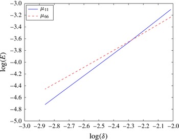
Figure 3 is a plot of the natural logarithm of the error versus that of the step size
 ${\it\delta}$
for the closed square case (
 ${\it\kappa}_{0}$
is taken as 0.01 in the numerical method). A uniform mesh is used with 60–140 panels. From the slopes of the curves, we can see that
 $E_{1}\sim {\it\delta}^{1.91}$
and
 $E_{6}\sim {\it\delta}^{1.45}$
, which is less than the second-order accuracy expected but better than first-order accurate. These convergence rates are typical of this method for other geometries as well. A simulation with 130 panels using a cosine distribution leads to an error less than
 $0.5\,\%$
for all loads.
Plot of
 $\log (E_{j})$
versus
 $\log ({\it\delta})$
for the closed square case at
 ${\it\kappa}_{0}=0.01$
and
 $h=3$
. The slopes of the lines are 1.91 and 1.45, respectively.

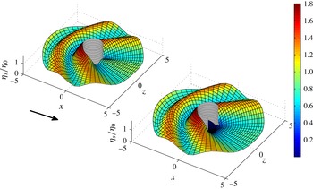
Modulus of complex surface amplitude of the diffraction field (2.23) over (a) a closed and (b) an open,
 ${\it\theta}_{0}={\rm\pi}/3$
, circular shell at an incident-wave direction of
 ${\it\beta}=0$
(indicated by arrow) with
 ${\it\kappa}_{0}=1.5$
.

Modulus of complex surface amplitude of the diffraction field (2.23) over (a) a closed and (b) an open,
 ${\it\theta}_{0}={\rm\pi}/3$
, circular shell at an incident-wave direction of
 ${\it\beta}=0$
(indicated by arrow) at the Helmholtz mode where
 ${\it\kappa}_{0}=0.65$
.

Modulus of complex surface amplitude of the diffraction field (2.23) over (a) a closed and (b) an open,
 $d=1.5$
, square shell at an incident-wave direction of
 ${\it\beta}={\rm\pi}$
(indicated by arrow) with
 ${\it\kappa}_{0}=1.5$
.

All results presented in this work are for a water depth
 $h=3$
. We used 75 and 100 panels for the circle and ellipse, respectively, and 112, 120 and 128 panels for the three square-shaped shells varying with the decreasing opening size. This is sufficient for graphical accuracy. The grid points are concentrated near the edges and the corners according to a cosine distribution for better accuracy. The Overhauser elements are known to perform well near corner points. For the radiation results, four modal terms were found to be sufficient for our purpose.
3.2. Diffraction results
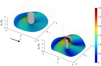
To understand the effect of opening the cylinder, it is useful to compare the amplitude of the free-surface elevation around the open and closed bodies. Figure 4 shows the amplitude of the wave field over a circular cylinder for a wave approaching along the positive
 $x$
axis (
 ${\it\beta}=0$
). These plots are useful because they indicate the position and amplitude of the highest waves. This is usually at the first point of contact with the obstacle. At low frequencies (
 ${\it\kappa}_{0}<0.1$
), the amplitude inside the body is comparable to the highest value outside because the wave does not ‘see’ the body so well. This visibility of the body becomes stronger as the frequency increases and the opening size decreases. The surface elevation is also representative of the pressure field over a certain region. Having a difference in the elevation on opposite sides of the cylinder creates a force acting in the normal direction. Because the field is symmetric about the
 $x$
axis in this case, the net force
 $f_{1}$
will be a result of the difference between the regions on the back and front sides of the body. We expect a higher load on an open body than on a closed one, provided the difference in surface elevation is comparable in both cases, because the opening area does not contribute to any force on the body that would balance the pressure on the back side.
Figure 5 shows the diffracted wave field amplitude over the circular shell as in the previous case but at the Helmholtz mode. The wave amplitude inside the shell rises to very high levels (according to the theory considered here) and more so as the shell opening size decreases. This leads to high loads on the body. The wave amplitude outside the shell is also greater when the body is open.
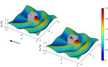
The last surface plot in this section is for an incident wave propagating in the negative
 $x$
direction and diffracting from a square shaped shell (figure 6). Because of the opening present, the force
 $f_{1}$
in this case will be different than the one for a wave along
 ${\it\beta}=0$
. The former case also shows a higher surface amplitude inside the body when compared to the latter case. The higher amplitude inside occurs on the opposite side of the opening as expected.
The rest of the results in this section are plots of the amplitudes of the loads acting on the shell because of the diffracted wave field. We note that the incident-wave potential does not contribute to the loads because the body has zero thickness. The loads are the result of the correction potential only.
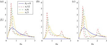
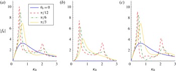
The results in figures 7 and 8 show the force and moment in the
 $x$
direction for different incident-wave directions. The moment results are very similar to the force ones and are of the order of the force results multiplied by a factor
 $h/2$
. This is to be expected, as the moment is a result of that force. In fact, this similarity extends to all forces and corresponding moments (in the same direction) in this work, and we will therefore restrict ourselves to forces for brevity. The results in the first plot of figure 7 indicate that a very large force results at lower frequency when the body is opened. Although the force on the closed body peaks in this range as well, the open-body force is observed to be much sharper and larger, especially as the opening gets smaller. This is the ‘harbour paradox’ (Mei, Stiassnie & Yue Reference Mei, Stiassnie and Yue2005a
, chap. 5). This force then decreases well below the closed-body case to peak again above the Helmholtz mode of the closed inner region. Note that, in reality, the forces would not be so large because of the effects of friction at the entrance and nonlinearities, which we have neglected here. An approximate theory for long waves that takes friction into account (Mei et al.
Reference Mei, Stiassnie and Yue2005a
, chap. 6) shows that the peak at the Helmholtz mode completely disappears when there is sufficient friction at the opening. The theory presented here will become a better approximation as the opening size increases. Nonlinearity can also play a role by moving the energy from the lower to the higher harmonics. This should be particularly important around the Helmholtz mode as the amplitude of the surface becomes larger. As indicated in Mei, Stiassnie & Yue (Reference Mei, Stiassnie and Yue2005b
, chap. 12), nonlinearity effects are expected to dominate (even over friction) as the harbour length increases along the direction of wave propagation compared to the width.
Diffraction forces
 $f_{1}$
on the circular shell in three incident-wave directions:
 ${\it\beta}=0$
(a),
 ${\it\beta}={\rm\pi}/2$
(b) and
 ${\it\beta}={\rm\pi}$
(c).

Diffraction moments
 $f_{4}$
on the circular shell in three incident-wave directions:
 ${\it\beta}=0$
(a),
 ${\it\beta}={\rm\pi}/2$
(b) and
 ${\it\beta}={\rm\pi}$
(c).

The elevation inside the closed shell is always zero. The load, which is related to the difference in elevation on opposite sides of the shell, results from the high-amplitude waves on the outer side of the wall just upstream of the shell. This is balanced, to a certain extent, by the difference downstream. In the case of an open shell, this balancing effect disappears and larger forces are observed. At the Helmholtz (pumping) mode, the elevation inside the shell is almost uniform except near the opening (Miles & Lee Reference Miles and Lee1975). The same thing is also observed for a moonpool with a bottom gap (Yeung & Seah Reference Yeung and Seah2007). The body is essentially acting as a Helmholtz resonator in this long-wave limit. As the body is opened, it becomes possible to excite the internal region, which leads to the larger loads. In between the two peaks, the elevation inside the shell is close to that outside. In fact, most of the pressure difference occurs close to the edges at the opening where wave heights are small. The resulting loads are significantly lower than those on a closed body.
When the incident wave approaches at
 ${\it\beta}={\rm\pi}$
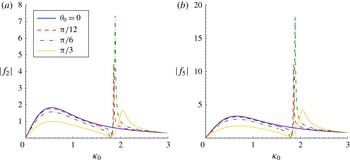
, even lower loads result in that frequency range when compared to the closed shell. In fact, we can see near-zero loads in that case (figure 7). This hints that, by properly choosing the opening size, it is possible to achieve zero loads on the body. The zero-load frequencies could be tuned to be close to the peak of the wave field spectrum in an irregular wave field. The results are also seen to be somewhat insensitive to changes in frequency, so the possibility of designing the opening to reduce loads on the structure may be viable. The results in figure 7(b) are also important because these loads only arise when the body is open. This is because of the asymmetry that is introduced by having an opening. These loads can be seen to be of the same order of magnitude as the loads when the wave is directed along the opening direction.
Figure 9 shows the force and moment on the circular shell in the
 $z$
direction when the incident wave approaches in that same direction. The interesting result here is the possibility of having a zero force and moment on the body for a certain frequency and for all openings as long as the body is open.
Diffraction loads (a)
 $f_{2}$
and (b)
 $f_{5}$
on the circular shell in incident-wave direction
 ${\it\beta}={\rm\pi}/2$
.

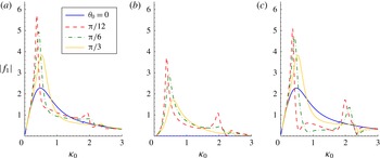
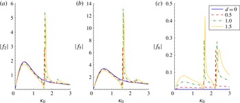
The results in figure 10 are for an elliptical shell and are analogous to those in figure 7. The loads appear similar to those of the circular shell, and the general behaviour can be described in a similar manner. This indicates that the shape of the harbour has little effect on the physical behaviour. The normalized loads on the elliptical shell are found to be slightly lower than those on the circular one when the body is open, in contrast to the closed case. The dimensional loads will be greater, though, because the elliptical shell is larger in size.
Diffraction forces
 $f_{1}$
on the elliptical shell in three incident-wave directions:
 ${\it\beta}=0$
(a),
 ${\it\beta}={\rm\pi}/2$
(b) and
 ${\it\beta}={\rm\pi}$
(c).

Because of symmetry, the force and moment in the
 $z$
direction and the yaw moment are only non-zero when the incident wave approaches at a direction
 ${\it\beta}={\rm\pi}/2$
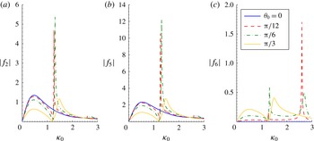
even when the body is open. We present those cases in figure 11. Again, the force and moment in the
 $z$
direction are similar. We notice that the loads decrease from the closed-body case when the opening increases. This has to do with higher wave elevations inside the shell and therefore less differences with the outside. High elevations inside are not observed except close to the resonance frequency. Again, it is possible to have points of zero loads at certain frequencies when the body is opened. The yaw moment in figure 11(c) is also of interest because it only appears for an open body. The behaviour is a bit more complicated for this moment than the rest of the loads, because it depends on forces in both horizontal directions. The forces do not balance because of the asymmetry created by the opening inside the body and in the wake, and the net effect is a moment about the
 $y$
axis.
Diffraction loads (a)
 $f_{2}$
, (b)
 $f_{5}$
and (c)
 $f_{6}$
on the elliptical shell in incident-wave direction
 ${\it\beta}={\rm\pi}/2$
.

The case of the square shell is similar to the circle and ellipse. Figure 12 shows the wave force in the
 $x$
direction for three incident-wave directions, while figure 13 shows the wave loads in the
 $z$
direction and the yaw moment when the incident wave approaches from the side in a manner analogous to figure 11. For loads resulting from beam waves, points of zero force are clearly possible for all opening sizes as long as the shell is open.
Diffraction forces
 $f_{1}$
on the square shell in three incident-wave directions:
 ${\it\beta}=0$
(a),
 ${\it\beta}={\rm\pi}/2$
(b) and
 ${\it\beta}={\rm\pi}$
(c).

Diffraction loads (a)
 $f_{2}$
, (b)
 $f_{5}$
and (c)
 $f_{6}$
on the square shell in incident-wave direction
 ${\it\beta}={\rm\pi}/2$
.

The first resonant wavenumbers for the open circular and square bodies in figures 7 and 12 can be compared to those of the corresponding closed bodies. Those latter ones are
 ${\it\kappa}_{0}={\rm\pi}/2$
for a square and
 ${\it\kappa}_{0}=1.8412$
for a circle moving in surge. This last value is the root of
 $\partial \text{J}_{1}({\it\kappa}_{0}r)/\partial r$
at
 $r=1$
for the Bessel function of the first kind and first order. An important question here is the following: Why do we observe resonance at low frequencies for the open shell although these are far from the first natural frequencies of the closed shell? A simple analogy can be made with the problems of wave propagation over a string or in a gas tube. It is well known that the resonant behaviour of a string connected to a wall is different from that with a free end. The same can be said about a gas tube with closed or open ends. For a closed–open tube (analogous to the open case), the first resonant wavenumber (
 ${\it\kappa}a={\rm\pi}/4$
) in a gas tube of length
 $2a$
becomes half of its value for the closed–closed tube (
 ${\it\kappa}a={\rm\pi}/2$
). The second resonant wavenumber (
 ${\it\kappa}a=3{\rm\pi}/4$
) for the closed–open tube is three times the first one (Kinsler et al.
Reference Kinsler, Frey, Coppens and Sanders2000). This is similar to what we observe for the open harbour, where the first resonance is dramatically shifted to lower frequencies as the shell is opened. The second resonance also occurs somewhere of the order of three times the first resonance. An equivalent statement is to say that damped systems (radiating open bodies) are known to have lower resonant frequencies. Naturally, our problem is more involved than the case of a string or gas tube because of the more complex geometries, the three-dimensional effects and the presence of an outer domain.
It was observed that, at certain opening size and frequency values, the load along the
 $x$
axis approaches zero. This behaviour is observed for an incident wave approaching at
 ${\it\beta}={\rm\pi}$
but not for the case when
 ${\it\beta}=0$
. This leads to the surprising observation that directing an open structure towards the incident waves leads to lower loads than directing it the opposite way around. We found that the values
 ${\it\theta}_{0}=[0.1441{\rm\pi},0.1265{\rm\pi}],d=0.89$
at wavenumbers
 $k=[0.916,0.704,0.726]$
are representative of the zero-load conditions (numerically
 $|\,f_{1}|<0.007$
) for the circular, elliptical and square bodies considered in this work.
3.3. Radiation results
Although the cylinder is bottom-mounted, it is still useful to know its radiation properties because it could still be connected to the bottom using a suitable joint that allows its motion or it could represent a reasonable model for truncated cylinders with a long enough draught. This approximation is expected to work better for the open shell because the fluid could escape through the opening easier than through the bottom gap and the effect of this gap will be less important.
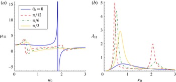
Figure 14 shows the added mass and damping coefficients of a surging circular shell. The closed-shell added mass shows resonant behaviour as expected. Opening the shell slightly increases the resonant frequency and drastically reduces the added mass at resonance. This is because the fluid can now escape the inner region. Another peak in added mass appears at lower frequencies, as was the case for diffraction forces. The damping coefficients also peak at these points. This range of frequencies is characterized by an increase in the free-surface elevation to very high levels, which causes high pressure differences across the wall. Again, as for the diffraction problem, the absence of a balancing force where the opening is located leads to a high net force on the shell.
Radiation surge (a) added mass
 ${\it\mu}_{11}$
and (b) damping
 ${\it\lambda}_{11}$
coefficients for the circular shell.

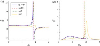
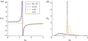
Figure 15 shows the coefficients for the swaying circular shell. The results indicate a slight decrease in both coefficients and a slight shift of resonance towards higher frequency as the opening size increases. Close to resonance, the added mass changes to finite extrema while the radiation damping significantly increases as waves from inside escape to the outer field. This case could be used as a wavemaker that generates a single desired frequency. The effect of resonance is reduced as the opening size increases.
Radiation sway (a) added mass
 ${\it\mu}_{22}$
and (b) damping
 ${\it\lambda}_{22}$
coefficients for the circular shell.

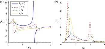
Figures 16 and 17 present the radiation coefficients for the elliptical shell moving in surge and sway, respectively. The results are qualitatively very similar to those of the circular cylinder. The magnitudes are slightly higher though. It is interesting to note that the resonance frequency is the same as that of the circular shell in the surge motion and lower in the sway motion. This is because the resonance in the sway direction is mostly governed by the length
 $b$
rather than
 $a$
.
Radiation surge (a) added mass
 ${\it\mu}_{11}$
and (b) damping
 ${\it\lambda}_{11}$
coefficients for the elliptical shell.

Radiation sway (a) added mass
 ${\it\mu}_{22}$
and (b) damping
 ${\it\lambda}_{22}$
coefficients for the elliptical shell.

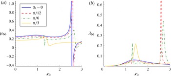
Figure 18 shows the yaw added inertia and damping coefficients for the elliptical shell. These coefficients are zero for the circular cylinder. The distinctive feature of these coefficients is the dominance of higher frequencies when compared to the other motions. Opening the shell leads to a large increase in the radiation damping close to the resonant frequency as in the previous cases. The fact that this occurs at a higher frequency requires further attention to this motion if open floating bodies are to be considered for ocean applications.
Radiation yaw (a) added inertia
 ${\it\mu}_{66}$
and (b) damping
 ${\it\lambda}_{66}$
coefficients for the elliptical shell.

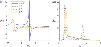
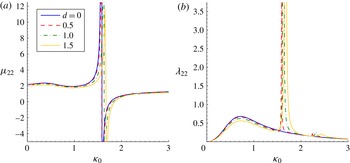
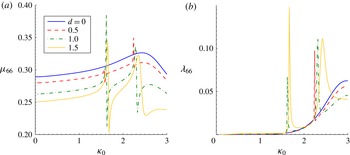
Figures 19–21 show the radiation coefficients on the square-shaped shell in the surge, sway and yaw directions. The results for surge and sway are similar to those of the circle and ellipse. The shape of the body does not play a significant role for these coefficients. One might expect that this would be different for the yaw motion because the force is completely a result of the body shape, and this is indeed the case. The yaw coefficients are seen to be quite different from those for the elliptical shell.
Radiation surge (a) added mass
 ${\it\mu}_{11}$
and (b) damping
 ${\it\lambda}_{11}$
coefficients for the square shell.

Radiation sway (a) added mass
 ${\it\mu}_{22}$
and (b) damping
 ${\it\lambda}_{22}$
coefficients for the square shell.

Radiation yaw (a) added inertia
 ${\it\mu}_{66}$
and (b) damping
 ${\it\lambda}_{66}$
coefficients for the square shell.

It is interesting to draw similarities of the radiation results with the case of a cylinder in a channel. This latter case was presented in Yeung & Sphaier (Reference Yeung and Sphaier1989a
,Reference Yeung and Sphaier
b
) as well as Linton & Evans (Reference Linton and Evans1993). First note that the added mass and damping in figures 14–21 appear to have their peak values over similar wavenumber positions. Furthermore, the magnitude of the damping at the peak (either peak) and the extent of the corresponding added mass jump behaviour are somewhat equal. This is not unlike the case presented in Linton & Evans (Reference Linton and Evans1993) in which the authors gave a heuristic argument of why the extent of the spikes in added mass and damping are nearly the same. The same argument can be used in this case if a simple pole in the complex load (
 ${\it\lambda}+\text{i}{\it\mu}$
) behaviour exists below the real axis. The similarity also extends to the case of a cylinder that is eccentric (not centred) along the channel width and swaying below the first cutoff frequency. In this case, propagating modes are possible in addition to the trapped mode, and the behaviour resembles our open-cylinder case. When there is no eccentricity, only the trapped mode is present and the radiation damping vanishes. This resembles what happens in the internal region of the closed-body case. One could not help but notice, then, the similarity in the radiation loads as presented in this last reference and our results. In particular, the peaks in the added mass and damping are shifted to higher wavenumbers as the opening size (analogous to eccentricity) increases. Recently, Sarkar, Renzi & Dias (Reference Sarkar, Renzi and Dias2014) reported a similar observation for the case of two flap-type energy converters facing each other, when compared to a single converter facing the coast.
3.4. Harbour with a ‘tongue’
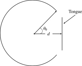
Finally, it would be interesting to see what is the effect of having a breakwater (tongue) at the mouth of the harbour, an idea suggested by the proposal to build floating harbours off the US coast (the Portunus Project). We will only present the most important case, which is when an incident wave approaches at
 ${\it\beta}={\rm\pi}$
and hits the breakwater. A simple harbour model consists of a circular shell and a straight tongue oriented along the
 $z$
axis (figure 22). This should capture most of the desired physical effects. The computer program described in this work has been modified to accommodate multiple bodies and the shell and tongue are considered as separate elements. We consider the effect of the distance
 $d$
of the tongue from the centre of the shell. The length of the tongue in this example is equal to one shell radius and the mouth size is taken to be
 ${\it\theta}_{0}={\rm\pi}/3$
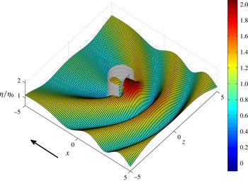
with the same definition as before. Figure 23 shows the amplitude of the free surface as a head wave hits the tongue.
Schematic for the harbour and breakwater model.

Modulus of complex surface amplitude of the diffraction field (2.23) over the circular shell with the tongue present at an incident-wave direction of
 ${\it\beta}={\rm\pi}$
with
 ${\it\kappa}_{0}=1.5$
.

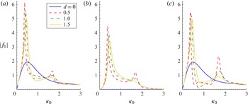
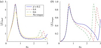
Figure 24 shows the amplitude of the force in the
 $x$
direction on both the shell and the tongue, and comparison is made in the first case with the shell without a tongue. The force is defined as in (2.22) and the area of the harbour is used for normalization. We used 100 panels on the circular shell and 67 on the tongue concentrated near the edges to obtain these results.
Diffraction force amplitude
 $|f_{1}|$
on (a) the shell and (b) the tongue.

The results indicate that the force on the shell is actually higher near the first resonant frequency when the tongue is present. Again, this is similar to the harbour paradox described earlier, and the limitations discussed earlier apply here as well. In particular, the high amplitude of the force is expected to be lower in reality, especially when the effective opening size becomes smaller. The position of the tongue does not seem to be significant in the frequency range considered though. The force on the tongue itself peaks in this range as well, although the total force is less than that on the shell. As the frequency of the incident wave increases, the breakwater comes into play and causes a reduction in the loads on the shell. The position of the tongue is significant in determining the second resonant frequency and the force amplitude at that peak. As the breakwater is moved farther away from the centre of the shell, both the second resonant frequency and force amplitude move to lower values. Solutions for harbour shapes other than a circular rim can be obtained with little difficulties.
4. Conclusions
We studied the effects of having open arbitrary cylindrical shells in a wave field. Both radiation and diffraction of waves from the body were considered and analysed. This work also presented a simple way to treat problems that can be modelled using a hypersingular integral equation. This last method is better conditioned and faster than a standard boundary-integral formulation used to model bodies approaching zero thickness. The results are also more reliable. The same concepts presented here can be extended to more complicated problems. We presented several new results for loads acting on open cylinders that are circular, elliptical and square in shape, with a special emphasis on the effect of the increasing opening size. We also presented plots for the free-surface elevation amplitude for wave radiation and diffraction from the bodies considered. The results are also extended to multiple bodies and the case of an open circular harbour with a frontal breakwater is considered.
The results indicate that a significant change in the load profile occurs when the body is opened. Specifically, very large loads appear at lower frequencies along the direction of the opening, especially when the shell is not opened widely. Smaller loads appear as the frequency increases when compared to the case of a closed shell, except when the frequency approaches the natural frequency of the internal region of the shell. Then the inside resonates partially, which causes higher loads. The loads in the direction perpendicular to the opening act differently. The increasing opening size leads to smaller loads except at resonance. Zero loads were found possible for certain frequencies and opening size combinations when the opening lies upstream. Zero loads are always possible for open structures in beam seas. In general, the opening has the possible advantage of decreasing the loads on the body.
With regards to wave radiation, it was found that the added mass decreases when the body is opened because the fluid in the direction of motion could escape from the shell. Open bodies were also found to radiate more waves close to resonance as compared to the closed ones. Free-surface plots also indicate regions of large oscillations and regions shielded from the incoming waves. These concepts should be useful for marine operations.
The problem of an open harbour with a protective breakwater was also considered. The results indicate that the breakwater might actually cause higher loads because of the inflicted resonance. The breakwater is effective, though, at high frequencies.
Acknowledgements
The first author (M.H.N.) acknowledges the support of an Ocean Technology Fellowship funded by the American Bureau of Shipping. The second (corresponding) author (R.W.Y.) is grateful to the American Bureau of Shipping for the establishment of an Endowed Chair in Ocean Engineering at UC Berkeley, which has made this and other research possible.
Appendix A
We have left the details of the treatment of the hypersingular integral to this appendix because they require some explanation. The integrals in (2.20) span the range of
 $[0,1]$
in the parameter
 $t$
and are only singular when the collocation point lies on one of the ends of that interval. The idea here is to approximate the kernel by its Taylor series close to the singular edge and to integrate analytically while performing numerical integration over the rest of the panel length. We will only consider the range of integration
 $[0,T]$
or
 $[1-T,1]$
for a collocation point placed on
 $t=0$
or
 $t=1$
, respectively, and for some suitable
 $T$
.
The kernels that are to be integrated here have different forms. They will include both hypersingular terms (
 $O(t^{-2})$
) and singular terms (
 $O(t^{-1})$
). The singular terms cancel out with those from the integral over the adjacent panel (principal values) provided the normal vector is continuous. The hypersingular ones do not though. However, as explained in Martin & Rizzo (Reference Martin and Rizzo1989), if the density belongs to
 $C^{1,{\it\alpha}}$
, it is possible to consider the finite part (in the sense of Hadamard) of these integrals. It follows then that all we have to do is analytically remove the singular and hypersingular parts.
One point to note here is that, while the density function is chosen to have enough continuity, our choice for straight panels to approximate the surface of the body will lead to a discontinuous normal vector at the panel edge and therefore a discontinuous kernel. That can be remedied by choosing a higher-order approximation for the shell. However, as pointed out in Martin & Rizzo (Reference Martin and Rizzo1996), a discontinuous density is allowed if the definition of the integral is changed to remove any unbounded terms. In fact, we can justify doing that in this case because, as we remove the singular terms, we effectively assume that we are using the same normal vector for the singular parts of the kernel but not for the regular parts. The following integrals (definitions) will be used:
 $$\begin{eqnarray}\displaystyle \int _{0}^{R_{0}}\frac{1}{s^{2}}\text{d}s & = & \displaystyle \lim _{{\it\epsilon}\rightarrow 0}\int _{{\it\epsilon}}^{R_{0}}\frac{1}{s^{2}}\text{d}s-\frac{1}{{\it\epsilon}}=-\frac{1}{R_{0}},\end{eqnarray}$$
 $$\begin{eqnarray}\displaystyle \int _{0}^{R_{0}}\frac{1}{s}\text{d}s & = & \displaystyle \lim _{{\it\epsilon}\rightarrow 0}\int _{{\it\epsilon}}^{R_{0}}\frac{1}{s}\text{d}s+\ln ({\it\epsilon})=\ln (R_{0}),\end{eqnarray}$$
 $$\begin{eqnarray}\displaystyle \int _{S-R_{0}}^{S}\frac{1}{(s-S)^{2}}\text{d}s & = & \displaystyle \lim _{{\it\epsilon}\rightarrow 0}\int _{S-R_{0}}^{S-{\it\epsilon}}\frac{1}{(s-S)^{2}}\text{d}s-\frac{1}{{\it\epsilon}}=-\frac{1}{R_{0}},\end{eqnarray}$$
 $$\begin{eqnarray}\displaystyle \int _{S-R_{0}}^{S}\frac{s}{(s-S)^{2}}\text{d}s & = & \displaystyle \lim _{{\it\epsilon}\rightarrow 0}\int _{S-R_{0}}^{S-{\it\epsilon}}\frac{s}{(s-S)^{2}}\text{d}s-\ln ({\it\epsilon})-\frac{S}{{\it\epsilon}}=-\ln (R_{0})-\frac{S}{R_{0}},\end{eqnarray}$$
 $$\begin{eqnarray}\displaystyle \int _{S-R_{0}}^{S}\frac{s^{2}}{(s-S)^{2}}\text{d}s & = & \displaystyle \lim _{{\it\epsilon}\rightarrow 0}\int _{S-R_{0}}^{S-{\it\epsilon}}\frac{s^{2}}{(s-S)^{2}}\text{d}s-2S\ln ({\it\epsilon})-\frac{S^{2}}{{\it\epsilon}}\nonumber\\ \displaystyle & = & \displaystyle -2S\ln (R_{0})+R_{0}-\frac{S^{2}}{R_{0}},\end{eqnarray}$$
 $$\begin{eqnarray}\displaystyle \int _{S-R_{0}}^{S}\frac{s^{3}}{(s-S)^{2}}\text{d}s & = & \displaystyle \lim _{{\it\epsilon}\rightarrow 0}\int _{S-R_{0}}^{S-{\it\epsilon}}\frac{s^{3}}{(s-S)^{2}}\text{d}s-3S^{2}\ln ({\it\epsilon})-\frac{S^{3}}{{\it\epsilon}}\nonumber\\ \displaystyle & = & \displaystyle -3S^{2}\ln (R_{0})+3R_{0}S-\frac{R_{0}^{2}}{2}-\frac{S^{3}}{R_{0}}.\end{eqnarray}$$
 $R_{0}<S$
, with
 $S$
a shorthand for
 $S_{j}$
, is a number chosen small enough to provide the required accuracy in the Taylor expansion in what follows. We note here, as was pointed out in Martin & Rizzo (Reference Martin and Rizzo1989), that the integrals with strong singularities are not independent of scaling the variable of integration. Here we integrate using the original variables to avoid that problem.
Using the fact that when the singular point is at
 $t=0$
or 1, then
 $R=St$
and
 $S(1-t)$
, respectively, we can Taylor-expand the kernel of (2.14) as
 $$\begin{eqnarray}\displaystyle \frac{\partial ^{2}G_{n}}{\partial n_{P}\partial n_{Q}} & = & \displaystyle A_{1}\left(\frac{4}{{\it\kappa}_{n}^{2}S_{j}^{2}(t-t_{s})^{2}}+1\right)\nonumber\\ \displaystyle & & \displaystyle -\,A_{2}\left[1+\frac{2\text{i}}{{\rm\pi}}\left(\ln \left(\frac{{\it\kappa}_{n}S_{j}|t-t_{s}|}{2}\right)+{\it\gamma}-\frac{2}{{\it\kappa}_{n}^{2}S_{j}^{2}(t-t_{s})^{2}}-\frac{1}{2}\right)\right]\nonumber\\ \displaystyle & & \displaystyle +\,O(R^{2}\ln (R)),\end{eqnarray}$$
 $$\begin{eqnarray}\displaystyle & \displaystyle A_{1}=\frac{{\it\kappa}_{n}^{2}}{4{\rm\pi}S_{j}^{2}}[a_{1}^{2}\sin ({\it\alpha}_{j})\sin ({\it\theta}_{j})+a_{2}^{2}\cos ({\it\alpha}_{j})\cos ({\it\theta}_{j})-a_{1}a_{2}\sin ({\it\theta}_{j}+{\it\alpha}_{j})], & \displaystyle\end{eqnarray}$$
 $$\begin{eqnarray}\displaystyle & \displaystyle A_{2}=-\frac{\text{i}{\it\kappa}_{n}^{2}\cos ({\it\theta}-{\it\alpha})}{8}. & \displaystyle\end{eqnarray}$$
 ${\it\gamma}$
is Euler’s constant,
 $a_{1}={\it\xi}_{j+1}-{\it\xi}_{j}$
and
 $a_{2}={\it\zeta}_{j+1}-{\it\zeta}_{j}$
. Clearly a hypersingular point of order
 $R^{-2}$
exists. This expression will be integrated analytically in the neighbourhood of the singular point in (2.20). The required integrals when the collocation point lies on the starting edge of the panel are then evaluated as
 $$\begin{eqnarray}\displaystyle I_{0} & = & \displaystyle \int _{0}^{R_{0}}\frac{\partial ^{2}G_{n}}{\partial n_{P}\partial n_{Q}}\text{d}s=A_{1}R_{0}\left(1-\frac{4}{{\it\kappa}_{n}^{2}R_{0}^{2}}\right)\nonumber\\ \displaystyle & & \displaystyle -\,A_{2}R_{0}\left[1+\frac{\text{i}}{{\rm\pi}}\left(2\ln \left(\frac{{\it\kappa}_{n}R_{0}}{2}\right)+2{\it\gamma}+\frac{4}{{\it\kappa}_{n}^{2}R_{0}^{2}}-3\right)\right]\!,\end{eqnarray}$$
 $$\begin{eqnarray}\displaystyle I_{1} & = & \displaystyle \int _{0}^{R_{0}}s\frac{\partial ^{2}G_{n}}{\partial n_{P}\partial n_{Q}}\text{d}s=A_{1}R_{0}^{2}\left(\frac{1}{2}+\frac{4\ln (R_{0})}{{\it\kappa}_{n}^{2}R_{0}^{2}}\right)\nonumber\\ \displaystyle & & \displaystyle -\,A_{2}R_{0}^{2}\left[\frac{1}{2}+\frac{\text{i}}{{\rm\pi}}\left(\ln \left(\frac{{\it\kappa}_{n}R_{0}}{2}\right)+{\it\gamma}-\frac{4\ln (R_{0})}{{\it\kappa}_{n}^{2}R_{0}^{2}}-1\right)\right]\!,\end{eqnarray}$$
 $$\begin{eqnarray}\displaystyle I_{2} & = & \displaystyle \int _{0}^{R_{0}}s^{2}\frac{\partial ^{2}G_{n}}{\partial n_{P}\partial n_{Q}}\text{d}s=A_{1}R_{0}^{3}\left(\frac{1}{3}+\frac{4}{{\it\kappa}_{n}^{2}R_{0}^{2}}\right)\nonumber\\ \displaystyle & & \displaystyle -\,A_{2}R_{0}^{3}\left[\frac{1}{3}+\frac{\text{i}}{{\rm\pi}}\left(\frac{2}{3}\ln \left(\frac{{\it\kappa}_{n}R_{0}}{2}\right)+\frac{2}{3}{\it\gamma}-\frac{4}{{\it\kappa}_{n}^{2}R_{0}^{2}}-\frac{5}{3}\right)\right]\!,\end{eqnarray}$$
 $$\begin{eqnarray}\displaystyle I_{3} & = & \displaystyle \int _{0}^{R_{0}}s^{3}\frac{\partial ^{2}G_{n}}{\partial n_{P}\partial n_{Q}}\text{d}s=A_{1}R_{0}^{4}\left(\frac{1}{4}+\frac{2}{{\it\kappa}_{n}^{2}R_{0}^{2}}\right)\nonumber\\ \displaystyle & & \displaystyle -\,A_{2}R_{0}^{4}\left[\frac{1}{4}+\frac{\text{i}}{{\rm\pi}}\left(\frac{1}{2}\ln \left(\frac{{\it\kappa}_{n}R_{0}}{2}\right)+\frac{1}{2}{\it\gamma}-\frac{2}{{\it\kappa}_{n}^{2}R_{0}^{2}}-\frac{3}{8}\right)\right]\!,\end{eqnarray}$$
 $$\begin{eqnarray}\displaystyle J_{0} & = & \displaystyle \int _{S-R_{0}}^{S}\frac{\partial ^{2}G_{n}}{\partial n_{P}\partial n_{Q}}\text{d}s=I_{0},\end{eqnarray}$$
 $$\begin{eqnarray}\displaystyle J_{1} & = & \displaystyle \int _{S-R_{0}}^{S}s\frac{\partial ^{2}G_{n}}{\partial n_{P}\partial n_{Q}}\text{d}s=A_{1}R_{0}^{2}\left(\frac{1}{T}-\frac{1}{2}-\frac{4}{{\it\kappa}_{n}^{2}R_{0}^{2}}\left(\ln (R_{0})+\frac{1}{T}\right)\right)\nonumber\\ \displaystyle & & \displaystyle -\,A_{2}R_{0}^{2}\left[\frac{1}{T}-\frac{1}{2}+\frac{\text{i}}{{\rm\pi}}\left(\left(\frac{2}{T}-1\right)\left(\ln \left(\frac{{\it\kappa}_{n}R_{0}}{2}\right)+{\it\gamma}\right)\right.\right.\nonumber\\ \displaystyle & & \displaystyle +\left.\left.\frac{4}{{\it\kappa}_{n}^{2}R_{0}^{2}}\left(\ln (R_{0})+\frac{1}{T}\right)+1-\frac{3}{T}\right)\right]\!,\end{eqnarray}$$
 $$\begin{eqnarray}\displaystyle J_{2} & = & \displaystyle \int _{S-R_{0}}^{S}s^{2}\frac{\partial ^{2}G_{n}}{\partial n_{P}\partial n_{Q}}\text{d}s=A_{1}R_{0}^{3}\left(\frac{1}{3}-\frac{1}{T}+\frac{1}{T^{2}}-\frac{4}{{\it\kappa}_{n}^{2}R_{0}^{2}}\left(\frac{2}{T}\ln (R_{0})-1+\frac{1}{T^{2}}\right)\right)\nonumber\\ \displaystyle & & \displaystyle -\,A_{2}R_{0}^{3}\left[\frac{1}{3}-\frac{1}{T}+\frac{1}{T^{2}}+\frac{\text{i}}{{\rm\pi}}\left(2\left(\frac{1}{3}-\frac{1}{T}+\frac{1}{T^{2}}\right)\left(\ln \left(\frac{{\it\kappa}_{n}R_{0}}{2}\right)+{\it\gamma}\right)\right.\right.\nonumber\\ \displaystyle & & \displaystyle +\left.\left.\frac{4}{{\it\kappa}_{n}^{2}R_{0}^{2}}\left(\frac{2}{T}\ln (R_{0})-1+\frac{1}{T^{2}}\right)-\frac{5}{9}+\frac{2}{T}-\frac{3}{T^{2}}\right)\right]\!,\end{eqnarray}$$
 $$\begin{eqnarray}\displaystyle & \hspace{-7.20007pt} & \displaystyle J_{3}=\int _{S-R_{0}}^{S}s^{3}\frac{\partial ^{2}G_{n}}{\partial n_{P}\partial n_{Q}}\text{d}s\nonumber\\ \displaystyle & \hspace{-7.20007pt} & \displaystyle \quad =A_{1}R_{0}^{4}\left(-\frac{1}{4}+\frac{1}{T}-\frac{3}{2T^{2}}+\frac{1}{T^{3}}-\frac{4}{{\it\kappa}_{n}^{2}R_{0}^{2}}\left(\frac{3}{T^{2}}\ln (R_{0})+\frac{1}{2}-\frac{3}{T}+\frac{1}{T^{3}}\right)\right)\nonumber\\ \displaystyle & \hspace{-7.20007pt} & \displaystyle \qquad -\,A_{2}R_{0}^{4}\left[-\frac{1}{4}+\frac{1}{T}-\frac{3}{2T^{2}}+\frac{1}{T^{3}}+\frac{\text{i}}{{\rm\pi}}\left(2\!\left(-\frac{1}{4}+\frac{1}{T}-\frac{3}{2T^{2}}+\frac{1}{T^{3}}\right)\!\left(\!\ln \left(\frac{{\it\kappa}_{n}R_{0}}{2}\right)\!+{\it\gamma}\!\right)\right.\right.\nonumber\\ \displaystyle & \hspace{-7.20007pt} & \displaystyle \qquad \left.\left.+\,\frac{4}{{\it\kappa}_{n}^{2}R_{0}^{2}}\left(\frac{3}{T^{2}}\ln (R_{0})+\frac{1}{2}-\frac{3}{T}+\frac{1}{T^{3}}\right)+\frac{3}{8}-\frac{5}{3T}+\frac{3}{T^{2}}-\frac{3}{T^{3}}\right)\right]\!.\end{eqnarray}$$
Here,
 $T=R_{0}/S$
. The integral of the whole Overhauser element could then be obtained by superposing the integrals above weighted by the values in (2.18)–(2.19).
Appendix B
We evaluate the integrals needed for the forces in (2.21) and (2.22). From (2.21) for
 $p=1,2,4,5,6$
:
 $$\begin{eqnarray}\displaystyle {\it\mu}_{kp}+\text{i}{\it\lambda}_{kp} & = & \displaystyle \frac{1}{Ah}\mathop{\sum }_{n=0}^{\infty }\frac{\sinh ({\it\kappa}_{n}h)}{{\it\kappa}_{n}M_{n}}\mathop{\sum }_{j=0}^{N}(n_{k})_{j}S_{j}\nonumber\\ \displaystyle & & \displaystyle \times \,\mathop{\sum }_{q=j-1}^{j+2}[{\it\varphi}_{n}^{p}]_{q}\left(b_{m1}+\frac{1}{2}b_{m2}+\frac{1}{3}b_{m3}+\frac{1}{4}b_{m4}\right)\!,\quad (k=1,2),\end{eqnarray}$$
 $$\begin{eqnarray}\displaystyle {\it\mu}_{kp}+\text{i}{\it\lambda}_{kp} & = & \displaystyle \frac{1}{Ah}\mathop{\sum }_{n=0}^{\infty }\frac{{\it\kappa}_{n}h\sinh ({\it\kappa}_{n}h)-\cosh ({\it\kappa}_{n}h)+1}{{\it\kappa}_{n}^{2}M_{n}}\mathop{\sum }_{j=0}^{N}(n_{k-3})_{j}S_{j}\nonumber\\ \displaystyle & & \displaystyle \times \,\mathop{\sum }_{q=j-1}^{j+2}[{\it\varphi}_{n}^{p}]_{q}\left(b_{m1}+\frac{1}{2}b_{m2}+\frac{1}{3}b_{m3}+\frac{1}{4}b_{m4}\right)\!,\quad (k=4,5),\end{eqnarray}$$
 $$\begin{eqnarray}\displaystyle {\it\mu}_{kp}+\text{i}{\it\lambda}_{kp} & = & \displaystyle \frac{1}{Ah}\mathop{\sum }_{n=0}^{\infty }\frac{\sinh ({\it\kappa}_{n}h)}{{\it\kappa}_{n}M_{n}}\mathop{\sum }_{j=0}^{N}S_{j}\nonumber\\ \displaystyle & & \displaystyle \times \,\mathop{\sum }_{q=j-1}^{j+2}[{\it\varphi}_{n}^{p}]_{q}\left[(z_{j}n_{1}-x_{j}n_{2})\left(\frac{1}{2}b_{m1}+\frac{1}{6}b_{m2}+\frac{1}{12}b_{m3}+\frac{1}{20}b_{m4}\right)\right.\nonumber\\ \displaystyle & & \displaystyle +\left.(z_{j+1}n_{1}-x_{j+1}n_{2})\left(\frac{1}{2}b_{m1}+\frac{1}{3}b_{m2}+\frac{1}{4}b_{m3}+\frac{1}{5}b_{m4}\right)\right]\cdot (k=6).\end{eqnarray}$$
 $q\in [j,j+2]$
, and for one on the right edge,
 $q\in [j-1,j+1]$
; and
 $(n_{k})_{j}$
is the normal component of the panel
 $C_{j}$
in direction
 $k$
. We also used
 $m=q-j+2$
so that
 $m\in [1,4]$
. Again,
 $m$
should be modified at the outermost panels to
 $m=q-j+1$
and
 $m=q-j+3$
for the left and right panels, respectively. The points
 $x_{j}$
and
 $z_{j}$
are the starting points of panel
 $C_{j}$
.
From (2.22):
 $$\begin{eqnarray}\displaystyle f_{k} & = & \displaystyle \frac{\text{i}\sqrt{{\it\nu}}}{A}\frac{\sinh ({\it\kappa}_{0}h)}{{\it\kappa}_{0}M_{0}}\nonumber\\ \displaystyle & & \displaystyle \times \,\mathop{\sum }_{j=0}^{N}(n_{k})_{j}S_{j}\mathop{\sum }_{q=j-1}^{j+2}[{\it\varphi}_{0}^{7}]_{q}\left(b_{m1}+\frac{1}{2}b_{m2}+\frac{1}{3}b_{m3}+\frac{1}{4}b_{m4}\right)\!,\quad (k=1,2),\end{eqnarray}$$
 $$\begin{eqnarray}\displaystyle f_{k} & = & \displaystyle \frac{\text{i}\sqrt{{\it\nu}}}{A}\frac{{\it\kappa}_{0}h\sinh ({\it\kappa}_{0}h)-\cosh ({\it\kappa}_{0}h)+1}{{\it\kappa}_{0}^{2}M_{0}}\nonumber\\ \displaystyle & & \displaystyle \times \,\mathop{\sum }_{j=0}^{N}(n_{k-3})_{j}S_{j}\mathop{\sum }_{q=j-1}^{j+2}[{\it\varphi}_{0}^{7}]_{q}\left(b_{m1}+\frac{1}{2}b_{m2}+\frac{1}{3}b_{m3}+\frac{1}{4}b_{m4}\right)\!,\quad (k=4,5),\end{eqnarray}$$
 $$\begin{eqnarray}\displaystyle f_{k} & = & \displaystyle \frac{\text{i}\sqrt{{\it\nu}}}{A}\frac{\sinh ({\it\kappa}_{0}h)}{{\it\kappa}_{0}M_{0}}\nonumber\\ \displaystyle & & \displaystyle \times \,\mathop{\sum }_{j=0}^{N}S_{j}\mathop{\sum }_{q=j-1}^{j+2}[{\it\varphi}_{0}^{7}]_{q}\left[(z_{j}n_{1}-x_{j}n_{2})\left(\frac{1}{2}b_{m1}+\frac{1}{6}b_{m2}+\frac{1}{12}b_{m3}+\frac{1}{20}b_{m4}\right)\right.\nonumber\\ \displaystyle & & \displaystyle +\left.(z_{j+1}n_{1}-x_{j+1}n_{2})\left(\frac{1}{2}b_{m1}+\frac{1}{3}b_{m2}+\frac{1}{4}b_{m3}+\frac{1}{5}b_{m4}\right)\right]\cdot \quad (k=6).\end{eqnarray}$$
 $q$
at the edges is the same as that used in treating the radiation coefficients.