1. Introduction
In recent years, the performance of exoskeleton robot has been continuously improved, and many powered exoskeletons have been successfully developed, such as BLEEX [Reference Zoss, Kazerooni and Chu1, Reference Kazerooni, Racine, Huang and Steger2], HULC [Reference Young and Ferris3], and HAL [Reference Di Natali, Poliero, Sposito, Graf, Bauer, Pauli, Bottenberg, De Eyto, O’Sullivan, Hidalgo, Scherly, Stadler, Caldwell and Ortiz4]. The powered exoskeleton requires high driving force, long endurance, and fast response [Reference Ouyang, Ding, Fan, Li and Yang5]. Therefore, driving mode and energy efficiency are concerned [Reference Sawicki, Beck, Kang and Young6]. The electric driving technology is mature, with a simple composition structure and easy control [Reference Giancarlo and Miguel7], while its power density is low and its dynamic characteristics are insufficient. The hydraulic driving has a high power density [Reference Sun, Ouyang, Mattila, Chen, Yang and Liu8]; however, there are high maintenance, large leakage, and serious pollution [Reference Shariatee, Akbarzadeh and Nabavi9]. Compared with the above modes, pneumatic driving not only has the characteristics of high power density, its pressed gas comes from the air, which shows good convenience and environmental protection.
Currently, pneumatic exoskeletons still have problems such as low driving efficiency and poor cruising ability [Reference Kim, Chang, Park and Kim10]. When the exoskeleton works, the load changes in real time and varies widely. Traditional pneumatic system adjusts the pressure through a servo valve to match the load changing. However, the throttling effect in valve port generates enormous energy loss [Reference Heo, Kim and Kim11], which not only causes low driving efficiency and affects its moving range but also causes the power system to generate heat, enlarge the heat dissipation equipment, and eventually increase the installed weight, which seriously constrains improvement of the exoskeleton.
Our team has been engaged in the research of powered exoskeleton and energy-efficient driving [Reference Zhang, Zhang and Elsabbagh12, Reference Zhang and Zhang13] and found that the system efficiency can be improved by optimizing the pneumatic actuator structure and driving control method. Also, much research work has been done by scholars in this area. For example, Blagojevic proposed different pneumatic pressures to drive the extension and retraction of the piston rod to reduce system losses [Reference Blagojevic, Seslija, Dudic and Randjelovic14]. Šešlija has applied pulse width modulation (PWM) and bypass valves to control pneumatic actuators to improve energy efficiency [Reference Šešlija, Čajetinac, Blagojević and Šulc15], while the PWM frequency does not match the frequency of the fast switching valve, which limited system performance. Adel used PWM control of fast switching valves with suitable frequency to improve the system performance [Reference Adel Elkashef, Aly, Mahmoud and Hossamel-din16]. Yang adopted bypass valves to maintain position accuracy in the constant velocity phase of the piston rod, which saved 12–28% of energy consumption compared to the traditional method [Reference Yang, Pu, Wong and Moore17]. Du presented a new bridge circuit to achieve energy conservation using the expansion and exhaust energy of compressed air, achieving energy reductions of 55–87% compared to the conventional circuit [Reference Du, Hu, Xiong, Jiang and Wang18]. Renn used a control method with fully digital valves to reduce the steady-state error of the system [Reference Renn, Cheng and Liao19]. Yang proposed a new booster valve with energy recovery function in order to improve the efficiency of the pneumatic system [Reference Yang, Tadano, Li, Kagawa, Peng, Zhang, Song and Wu20, Reference Yang, Tadano, Li and Kagawa21].
The above literature shows that the optimization of driving system and control method has improved performance and efficiency of the pneumatic system to a certain degree. For powered exoskeleton, the pneumatic actuator is subjected to the greater load varying and the greater nonlinearity, so better solutions need to be proposed to enhance performance. Our team found that the human body energy consumption is much less when the human body makes the same action as the bionic robot complete, this low energy consumption is resulting from the human skeletal structure, muscle scale, and energy supply mode. Therefore, based on the human skeletal muscle structure and driving characteristics, this paper proposes a bionic multi-chamber pneumatic actuator, which aims to enhance the exoskeleton power performance and efficiency.
The rest of this paper is organized as follows, the second part presenting the bionic multi-muscle driving mechanism and multi-chamber pneumatic actuator design. The third part is the analysis of driving characteristic, including the analysis of output force and the analysis of output energy efficiency. Simulation on load matching control is conducted in the fourth part. The fifth part contains the development of the multi-chamber pneumatic actuator and the exoskeleton testing platform, which is used to study the drive characteristics and performance.
2. Bionic mechanism and structure design
2.1. Bionic muscle scale mechanism
Muscle is an important part of the human driving system, and joint movements are all related to the muscle. Muscle obtains motion energy and signals from blood vessel and nerves respectively to realize different movements of the body with high energy efficiency and flexibility, and the basic working unit in a muscle is called motor unit. As the different biomechanical demands are generated in different movements, when driving a joint movement, all motor units are usually not activated at the same time and the activated motor units are not always uniformly distributed throughout the muscle [Reference Hudson, Gandevia and Butler22]. Therefore, to ensure that the output power of the muscle matches the load in real time, the muscle evolves into the following scale mechanism [Reference Purves, J.Augustine, Fitzpatrick, Hall, Lamantia and White23].
-
1. There are multiple motor units inside a skeletal muscle.
-
2. There are scale differences between the motor units, and the output forces of the motor units are different at different scales.
-
3. There are different recruitment combinations of motor units for various loads.
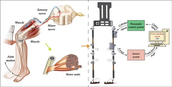
In this paper, the joints of the powered exoskeleton imitate the skeletal joints of the human body, as shown in Fig. 1, the pneumatic actuators of the exoskeleton imitate the human muscle, while the pneumatic circuit imitates the human blood vessel to provide motion energy, and the control signal imitates the human control nerves. Based on the human muscle scale mechanism, the structural composition and driving mechanism of the powered exoskeleton are designed as follows. The pneumatic actuator consists of multi-chamber, and there are scale differences between all chambers, and the output force of different chambers is different. What is more, facing the various loads on the exoskeleton, the control system recruits different chamber combinations to realize the action in real time.
2.2. Multi-chamber pneumatic actuator design
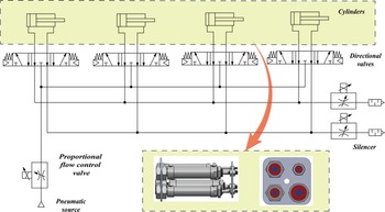
Based on the muscle mechanism, a bionic multi-chamber pneumatic actuator is designed for the problem that the traditional pneumatic actuator cannot match the various load which results in low energy efficiency. The novel design for the multi-chamber actuator is described as follows. Imitating the muscle structural features, the bionic multi-chamber pneumatic actuator is composed of four working chambers with different effective areas (here realized by cylinders), each chamber is connected to a 3/5 directional valve, which controls rodless chamber and rod chamber to connect with the high-pressure gas and low-pressure gas, respectively, as shown in Fig. 2, where the directional valves imitate human motor neurons and the different chamber imitate muscle motor units. Imitating the dimensional difference characteristics of motor units, for the multi-chamber pneumatic actuator, the directional valve controls the chamber with the smallest effective area to form a small motion unit, and the output force is the smallest when the chamber connects to the high-pressure gas. As the same principle, the directional valve controls the chamber with the largest effective area to form a large motion unit, and the output force is the largest when the chamber connects to the high-pressure gas, imitating the different recruitment combinations of motor unit. By the control of 3/5 directional valves, different output forces can be obtained for the different recruitment combinations of the actuator chambers, which can meet the time-varying demand of the load and greatly improve energy efficiency of the exoskeleton.
Schematic diagram of the multi-chamber pneumatic actuator structure.

Bionic multi-muscle scale mechanism for the powered exoskeleton.

As shown in Fig. 2, a schematic diagram of the multi-chamber pneumatic actuator structure is displayed, which consists of four cylinders of the different effective areas connected in a parallel form. The four cylinders are equivalent to the different scales of motor units in human muscle. The 3/5 directional valve belongs to the mid-drain type. When the directional valve is in the neutral position, it makes the pneumatic inlet and outlet connect to the atmosphere, which ensures that the chambers will not interfere with each other during the movement and enhances the reliability of the actuator output.
3. Analysis of driving characteristic
3.1. Analysis of output force
The multi-chamber pneumatic actuator realizes different combinations of chambers by controlling the directional valves, which achieves different effective areas for the action. Define the control signals of the directional valves as
 $x=[x_{1}x_{2}x_{3}x_{4}]$
. When the pneumatic actuator piston rod extends, where
 $x_{i}=1(i=1\sim 4)$
it indicates that the rodless chamber (left chamber) and the rod chamber (right chamber) are connected to the high-pressure gas and low-pressure gas, respectively. When the actuator piston rod is retracted, where
 $x_{i}=1(i=1\sim 4)$
it indicates that the rodless chamber and the rod chamber are connected to the low-pressure gas and high-pressure gas, respectively.
The relationship between the effective area of the left chamber
 $A_{L}$
, the effective area of the right chamber
 $A_{R}$
, and the directional valve control signal
 $x$
can be expressed.
 \begin{equation} A_{L}=\sum _{i=1}^{4}A_{Li}x_{i} \end{equation}
 \begin{equation} A_{R}=\sum _{i=1}^{4}A_{Ri}x_{i} \end{equation}
Ignoring the throttling pressure loss of 3/5 directional valves, the output force of the novel actuator is as shown in Eq. (3).
 \begin{equation} F_{o}=p_{L}A_{L}-p_{R}A_{R}-f \end{equation}
where
 $f$
is the frictional force.
From Eqs. (1)–(3), the output force is obtained.
 \begin{equation} F_{o}=p_{L}\sum _{i=1}^{4}A_{Li}x_{i}-p_{R}\sum _{i=1}^{4}A_{Ri}x_{i}-f \end{equation}
Equation (4) shows that the output force of the multi-chamber actuator can be changed with the different controls of the directional valves.
The relationship between the combination
 $N_{c}$
and the number of chambers
 $n$
is given.
 \begin{equation} N_{c}=\sum _{i=0}^{n}C_{n}^{i} \end{equation}
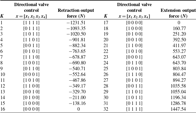
In this paper, four cylinders of different diameters are selected as the chambers. When the actuator piston rod extends, there are 16 types of control signals for directional valves, producing 16 different output thrusting forces. Similarly, when the actuator piston rod retracts, it realizes 16 different output pulling forces. So the multi-chamber actuator can achieve totally 32 different output forces, as shown in Table I, where K is defined as the chamber combination rank.
Output forces in different control combinations.

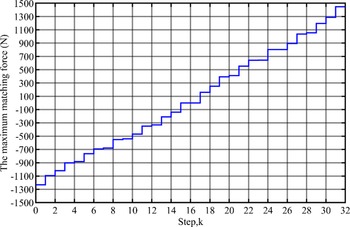
The output force curve of the multi-chamber pneumatic actuator is drawn, as shown in Fig. 3, the maximum output thrusting force is 1447.54 N, and the maximum output pulling force is −1231.51 N. The output force shows a step change, and the change amplitude is affected by the different effective areas of the chamber. Therefore, it can be reasonably inferred that optimizing the selection of different effective areas can result in different output forces. At the same time, as the number of chambers increases (e.g., more than four), the more the actuator output force is, and the more delicate the change is.
The output force curve of the multi-chamber pneumatic actuator.

3.2. Analysis of energy efficiency
3.2.1. Analysis of the traditional actuator
The traditional pneumatic driving system mainly includes pneumatic source, servo-proportional valve, and single-chamber actuator. The traditional pneumatic system matches the robot load through the servo-proportional valve, whose throttling effect causes much heat and energy loss, affecting the reliability and motion range of the powered exoskeleton.
The energy in the pneumatic system is derived from
 $p_{s}$
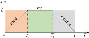
, ignoring leakage loss. As shown in Fig. 4, a cycle of action of the actuator consists of an extension time
 $T_{e}$
, a stop time
 $T_{s}$
, and a retraction time
 $T_{r}$
.
Sequence diagram of the pneumatic actuator action.

The mass flow rate into the pneumatic actuator chamber can be expressed [Reference Karpenko and Sepehri24].
 \begin{equation} \left\{\begin{array}{l} q_{mL}=\dfrac{V_{L}}{rRT}\cdot \dfrac{dp_{L}}{dt}+\dfrac{p_{L}}{RT}\cdot \dfrac{dV_{L}}{dt}\\[7pt] q_{mR}=\dfrac{V_{R}}{rRT}\cdot \dfrac{dp_{R}}{dt}+\dfrac{p_{R}}{RT}\cdot \dfrac{dV_{R}}{dt} \end{array}\right. \end{equation}
where
 $q_{mL}, q_{mR}$
are the mass flow rates of the rodless chamber and the rod chamber, respectively.
 $p_{L}, p_{R}$
are the pneumatic pressure of the rodless chamber and the rod chamber, respectively.
 $V_{L}, V_{R}$
are the gas volumes of the rodless chamber and the rod chamber, respectively. T is the adiabatic temperature of the gas; r is the adiabatic ratio coefficient of the gas. R is the gas constant.
 $\rho _{a}$
is the air density in the standard state.
 $q_{{V_{a}}}$
is the volume flow rate in the standard state. However, the energy consumed by a traditional pneumatic system is expressed.
 \begin{equation} q_{{V_{a}}}=\frac{q_{m}}{\rho _{a}} \end{equation}
 \begin{equation} E_{1}=\frac{\int _{0}^{T_{e}}p_{s}q_{mL}dt+\int _{0}^{T_{r}}p_{s}q_{mR}dt}{\rho _{a}} \end{equation}
3.2.2. Analysis of multi-chamber actuator
The multi-chamber actuator recruits the different motor units according to the value of the load and provides the corresponding mass flow rate, which can significantly reduce the throttling loss of the valves and improve the energy efficiency of the system. The energy consumed by the multi-chamber actuator driving system is expressed.
 \begin{equation} E_{2}=\frac{\int _{0}^{T_{e}}p_{s}\left(\sum _{i=1}^{4}x_{i}q_{mLi}\right)dt+\int _{0}^{T_{r}}p_{s}\left(\sum _{i=1}^{4}x_{i}q_{mRi}\right)dt}{\rho _{a}} \end{equation}
4. Simulation on load matching control
4.1. Control strategy
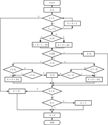
The load matching for the novel actuators is how to select the best combination of chambers according to the variable load and minimize the throttling loss. While meeting the requirement for driving force, the combination of chambers must also satisfy the requirement of displacement. Based on the trend prediction of displacement, the effective area can be adjusted to reduce the tracking error. When the tracking error e is positive, it indicates that the output force is less than the load; otherwise, the output force is more than the load. The control strategy is shown in Fig. 5.
Load matching control strategy of multi-chamber actuator.

Firstly, compare the load
 $F_{\text{Load}}$
with the maximum output force
 $F_{k}$
, and force error
 $\Delta F=F_{\text{Load}}-F_{k}$
. The force error
 $\Delta F\gt 0$
(at the piston rod retraction) indicates that the current output force satisfies the load demand, which may not be the closest to the load. Thus, to upgrade the rank
 $(k=k+1)$
, when
 $F_{\text{Load}}\lt F_{k}$
, the force error
 $\Delta F\lt 0$
, which indicates that the current output force cannot satisfy the load demand, and there may be a situation that the displacement requirement cannot be satisfied, which indicates that the rank k− 1 of the chamber combination is more appropriate and can be the initial selection value.
During the piston rod extension, when
 $\Delta F\gt 0$
, it indicates that the current output force cannot drive the load, and there may be a situation that the proportional flow valve port is fully open also cannot satisfy the displacement requirement. Thus, to upgrade a rank
 $(k=k+1)$
, when
 $F_{\text{Load}}\lt F_{k}$
, the force error
 $\Delta F\lt 0$
, which indicates that the current output force satisfies the load demand and is the closest to the load. So, the rank
 $k$
is more appropriate, which is the initial selection.
Then, the current displacement tracking error
 $e$
is compared to the threshold value
 $\delta _{1}$
. If
 $e\leq | \delta _{1}|$
, it indicates that the current output satisfies the load and continues to hold the rank
 $k$
constant. If
 $e\gt | \delta _{1}|$
, the derivative of the displacement tracking error
 $e'$
is compared with the boundary value of the error derivative
 $\delta _{2}$
. When
 $e$
is positive and
 $e'\geq \delta _{2}$
, it indicates that the displacement tracking error has a tendency to expand, and the rank
 $k$
needs to increase with the
 $\Delta k_{1}$
to accelerate the speed of reducing the error and improve the tracking accuracy. When
 $e'\lt \delta _{2}$
, it indicates that the displacement tracking error has a tendency to reduce, and further compared with the maximum displacement tracking error
 $\delta _{3}$
, if
 $e\lt \delta _{3}$
, the rank
 $k$
is kept constant, and conversely, the rank
 $k$
is increased by
 $\Delta k$
. When
 $e'\leq -\delta _{2}$
, which indicates a tendency of the displacement tracking error to expand, it reduces the rank
 $k$
by
 $\Delta k_{1}$
to reduce the displacement tracking error; when
 $e'\gt -\delta _{2}$
, it indicates that the displacement tracking error has a tendency to reduce, compared with the maximum displacement tracking error
 $\delta _{3}$
; if
 $e\gt -\delta _{3}$
, keeping the current rank
 $k$
unchanged, otherwise, reducing the rank
 $k$
. Finally, the selected rank
 $k\in [1,\left.Nc]\right.$
. When
 $k\notin [1,\left.Nc]\right.$
, if
 $k\lt 1$
, then
 $k=1$
, if
 $k\gt 32$
, then
 $k=32$
.
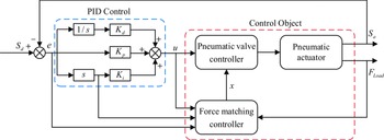
Based on the matching control strategy, a multi-chamber actuator closed-loop control system is established, as shown in Fig. 6.
 $S_{d}$
is the desired displacement,
 $S_{a}$
is the actual displacement,
 $x$
is the control signal of the directional valves, and
 $F_{o}$
is the output force of the multi-chamber actuator. The control system realizes double closed-loop control of displacement and force. The PID controller is mainly applied to the displacement control, according to the displacement error
 $e$
, feedback to the proportional flow valve to control the flow
 $q_{m}$
, which controls the piston rod moving. The load matching controller selects the chamber combination according to the load, reducing the throttling loss and improving the energy efficiency.
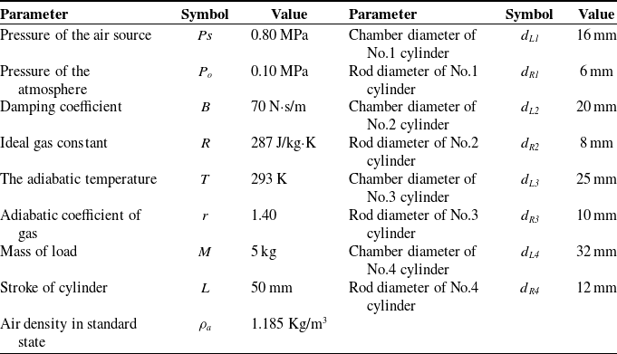
Parameters of the multi-chamber actuator simulation.

Schematic of multi-chamber actuator control system.

4.2. Control simulation
The simulation model is established based on MATLAB, and the parameters of the multi-chamber actuator are shown in Table II. Set the desired displacement
 $x_{d}=0.02\sin (2t)$
, and PID controller parameters
 $K_{p}=50, K_{d}=2, K_{i}=0$
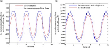
. During the displacement tracking control, different loads are added to test the matching performance. The load shown in Fig. 8(a) is
 $F_{\text{Load}}=500\sin (2t)$
. The load shown in Fig. 9(b) is
 $F_{\text{Load}}=800\sin (1.5t)+100$
, where the rank adjustment value is set to
 $\Delta k=2, \Delta k_{1}=1$
.
As can be seen from Fig. 7, the output force of the multi-chamber actuator can be adjusted in real time to match the load. When the load increases, the effective area of the actuator is increased by increasing the motor units, which causes the output force to also increase. When the load decreases, the effective area of the actuator is reduced by reducing the number of motor units, which decreases the output force.
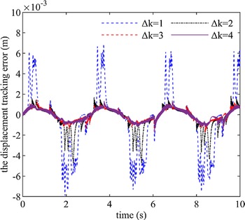
The effect of the rank on displacement tracking error is studied for a load of
 $F_{\text{Load}}=500\sin (2t)$
and a desired displacement of
 $x_{d}=0.02\sin (2t)$
, as shown in Fig. 8. Displacement tracking error is maximum when
 $\Delta k=1$
. When
 $\Delta k=2, \Delta k=3, \Delta k=4$
, the displacement error is relatively close, and when
 $\Delta k=4$
, the displacement tracking error
 $e$
is the smallest. The results show that the adjustment
 $\Delta k$
can improve displacement tracking accuracy.
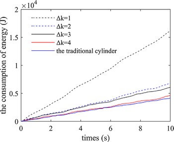
In order to research the influence of the adjustment
 $\Delta k$
on energy consumption, the energy consumption in different
 $\Delta k$
and the conventional actuator are plotted as shown in Fig. 9. The energy consumption of multi-chamber actuator varies with different
 $\Delta k$
. When
 $\Delta k=4$
, the energy consumption is 6772.60 J; when
 $\Delta k=1$
, the energy consumption is 4176.79 J. As the
 $\Delta k$
increases, the total energy consumed also increases. Meanwhile, the energy consumption of conventional actuator is about 16,165.40 J, which can be seen that the multi-chamber actuator is more effective.
Load matching curves. (a) The load is
 $F_{\text{Load}}=500\sin (2t)N$
, (b) The load is
 $F_{\text{Load}}=$
 $800\sin (1.5t)+100N$
.

Displacement tracking error in the different rank adjustment.

Energy consumption in the different rank adjustment.

In conclusion, the multi-chamber actuator can recruit different motor units according to the variable load and complete real-time load matching through control strategy, showing excellent energy efficiency advantages. Within a certain displacement tracking error range, the actuator energy consumption can be reduced by decreasing the rank adjustment value
 $\Delta k$
. On the other hand, by increasing the rank adjustment value
 $\Delta k$
, the displacement accuracy can be improved while increasing the actuator energy consumption. Therefore, when setting the rank adjustment value
 $\Delta k$
, multi-performance should be considered including load demand and energy consumption.
5. Experiment and discussion
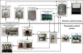
The prototype of the multi-chamber pneumatic actuator is developed to test the output characteristics, and a performance experimental platform is built, as shown in Fig. 10. The performance experimental platform consists of air pressure control system and electrical control system, where the solid black line indicates the flow of pressed gas and the dotted black line indicates the flow of electronic signal.
The experimental schematic of performance test system.

The air compressor converts the mechanical energy into the energy of pressed gas. The pressed gas passes through the pipeline to the novel actuator via 2/2 switching valve group and 3/5 directional valve group. The data acquisition card gets the fluid data (flow rate and pressure) and the mechanical data (displacement and force) to the computer. The computer sends commands to the 3/5 directional valve group controller and the 2/2 switching valve group controller through the data acquisition card to adjust the magnitude of the 3/5 directional valve group and the 2/2 switching valve group, respectively.
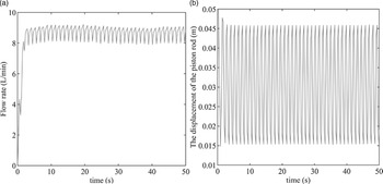
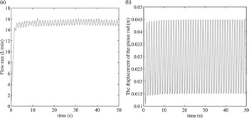
The working pressure is set to 0.3 MPa, and the actuator is driving the constant load through the combination of different chambers, respectively. The flow rate and displacement in the control signal
 $x=[1100]$
and
 $x=[1110]$
are shown in Fig. 11 and Fig. 12, which shows that the flow rate varies periodically with displacement. When driving the same load, the flow rate in control signal
 $x=[1110]$
is larger than the flow rate in
 $x=[1100]$
combination, up to 1.8 times, which indicates that the former one consumes more energy. Therefore, when facing the same load, the fewer the number of working chambers recruited, the more energy-efficient it is.
Driving curves in
 $x=[1100]$
. (a) The flow rate; (b) the displacement.

Driving curves in
 $x=[1110]$
. (a) The flow rate; (b) the displacement.

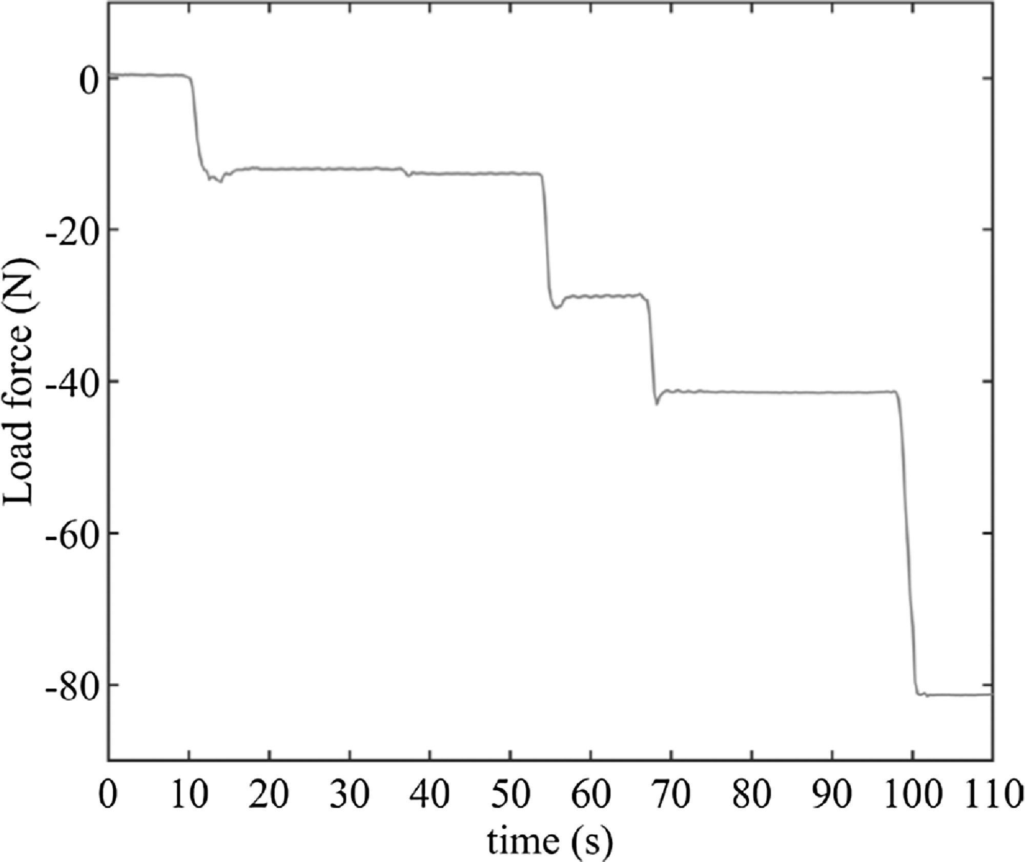
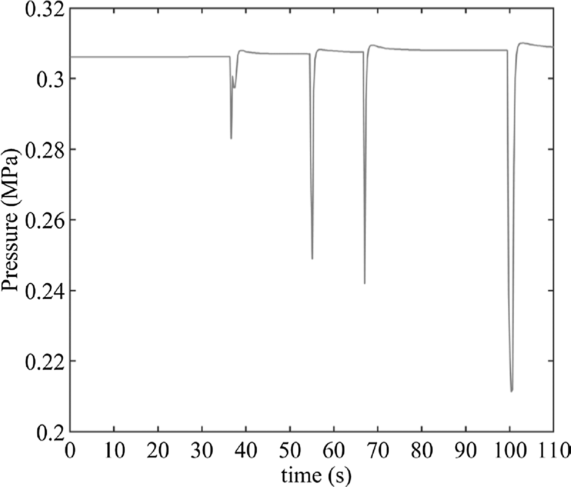
Testing the performance of driving the variable load. Figure 13 illustrates the different values of the load; it can be seen that the actuator can match the variable loads in real time. Control signal is switched among
 $x=[1000], x=[0010], x=[1100]$
, and
 $x=[1110]$
. Figure 14 indicates that the pressure changes under different control signals, and the driving force jumps during the switching gap of different chamber combinations, which is unfavorable for the compliance control and should be considered in the structural design and control strategy.
The variable loads in real time.

Pressures for different loads.

Diagram of the exoskeleton wearing test.

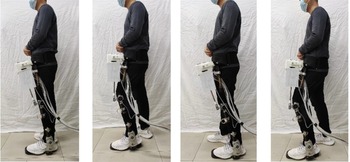
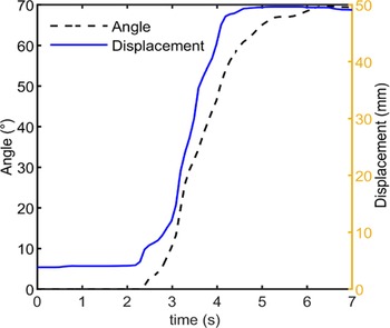
The prototype of the pneumatic-driven exoskeleton is developed to verify the performance of multi-chamber actuator, as shown in Fig. 15. The actuator displacement and joint motion curves are shown in Fig. 16. It can be seen that the exoskeleton joint is at rest from 0 to 2.3 s, and it starts to move from 2.3 s to 6 s, the rotation angle of the knee joint increases with the actuator extension, and the piston rod moves to the maximum displacement after 6 s. The experimental data show that the multi-chamber actuator is able to drive the exoskeleton joint moving normally.
Curves of displacement and joint motion.

6. Conclusion
In this paper, a novel bionic multi-chamber pneumatic actuator for powered exoskeleton is researched, including bionic design, theoretical analysis, simulation verification, and experimental testing. The following conclusions are obtained, and the multi-chamber pneumatic actuator structure and drive method are designed to imitate the human skeletal muscle and recruitment method. With four cylinders of different effective areas, it realizes 32 different chamber combinations that can match a wide range of loads. The control strategy and control method of multi-chamber actuator are planned, and the simulation is performed to prove that different motor units can be recruited to realize different load matching in real time. The energy consumption of the novel actuator can be reduced by reducing the rank adjustment value
 $\Delta k$
. The displacement accuracy can be improved by increasing the rank adjustment value
 $\Delta k$
. Finally, the prototype of the multi-chamber actuator is developed, and the driving performance test is completed to prove the effectiveness of the bionic actuator in driving variable loads and high energy efficiency.
Consent to participate
Not applicable.
Consent to publish
The work described has not been submitted elsewhere for publication, in whole or in part, and all the authors listed have approved the manuscript that is enclosed.
Authors contributions
All authors have made substantial contribution. Delei Fang and Jianwei Wang proposed the bionic design and made the theoretical analysis. Ming Yang and Yan Zhang designed the experiment scheme and analyzed the results. Junxia Zhang and Peng Zhang modified the paper.
Funding
This work was supported in part by the Hundred Cities and Hundreds Parks Project-Key Nutrition and Health Technology and Intelligent Manufacturing(21ZYQCSY00050), Open Project Fund of Tianjin Key Laboratory of Integrated Design, and Online Monitoring of Light Industry and Food Engineering Machinery and Equipment, 2020LIMFE05.
Competing interests
Not applicable.
Availability of data and materials
Not applicable.