I. INTRODUCTION
Time-domain boundary integral equation (TDIE) methods are being increasingly applied to the analysis of complex broadband electromagnetic (EM) scattering and transient radiation problems [Reference Yilmaz, Jin and Michielssen1]. Commonly, the marching-on-in-time (MOT) schemes are the primary candidate to solve the TDIEs numerically [Reference Geranmayeh, Ackermann and Weiland2]. The MOT recipes, however, suffer from late-time instability. Much work has been done to postpone or filter out the occurrence of exponentially growing fluctuations on the tail of response. Nonetheless, among generations of TDIE-based solvers, the marching-on-in-order, also referred as marching-on-in-degree (MOD) [Reference Yu, Fang and Zhou3], schemes are solely the only TDIE methods that are always stable [Reference Chung4]. In the MOD, a set of causal and orthogonal entire-domain basis functions, namely the weighted Laguerre polynomials, are used to represent the temporal variation of the unknowns [Reference Chung4]. This allows to handle the time integrations and derivatives fully analytically and integrate out the time variable [Reference Geranmayeh, Ackermann and Weiland2]. Recently, in an advanced version of the MOD (AMOD), the temporal testing is performed before the spatial testing whereby the unrealistic assumption of no changes for the unknown transient quantity within the subdomains is avoided and the accuracy is improved [Reference Ji, Sarkar, Jung, Yuan and Salazar-Palma5].
The dominant cost of the MOT and (A)MOD methods are mainly the computation of past solution couplings involving space–time convolution of the induced currents with the Green's function. The computational cost of the classical MOT schemes scales as O(N gN tN s2), where N t and N s denote the number of subdomain temporal and spatial basis functions, respectively, and N g is the maximum number of the last retarded time steps in which the scatterer subdomains interact. Depending on the sizes of the scatterer, mesh, and time step as well as frequency content of the excitation, the longest tail of the delayed samples N g may vary from N g ≪ N t to N g of O(N t), e.g., for planar surfaces N g is typically of  . In the MOD methods, independent from the problem in hand always N g = N t is obtained, which apparently raises the total computational cost to O(N t2N s2). However, N t in the MOT and MOD methods is not conceptually the same. In the MOD methods, the temporal degrees of freedom of the surface current density N t represents the time–bandwidth product of the waveforms to be approximated [Reference Chung4]. Thus, Jung et al. [Reference Jung, Ji, Sarkar, Salazar-Palma and Yuan6] concluded that the cost of the MOD is larger than the MOT when the number of time steps is not too large. Except the few low-order Laguerre polynomials that contribute dominantly to the very early stages, the entire-domain temporal expansion functions of the MOD are much smoother than the Lagrange bases of the MOT with local support in time. Moreover, the MOT recipes generally use point matching testing in time whereas the MOD schemes employ the Galerkin's method for temporal testing. As a result, the MOT methods are not as accurate as the MOD methods [Reference Geranmayeh, Ackermann and Weiland2, Reference Jung, Ji, Sarkar, Salazar-Palma and Yuan6].
The MOT solvers have been accelerated by the plane wave time-domain (analogous to the fast multiple method in frequency domain) [Reference Aygun, Fischer, Meng, Shanker and Michielssen7] and fast Fourier transform (FFT)-based algorithms [Reference Yilmaz, Jin and Michielssen1]. In the FFT-based TDIE methods, the convolution products are calculated based on (Toeplitz)–block–Toeplitz properties (constant along diagonals) of the impedance matrices [Reference Hu, Chan and Xu8, Reference Bleszynski, Bleszynski and Jaroszewicz9]. In [Reference Yilmaz, Weile, Jin and Michielssen10], the unknowns of uniformly meshed planar structures are separated into the local x and y components (i.e., four mutual orientations) and a two-dimensional (2-D) FFT has been exploited for circular convolutions. On the other hand, the periodicity-based method of moment (MoM) takes advantages of similar properties to analyze large finite antenna arrays [Reference Bleszynski, Bleszynski and Jaroszewicz11]. Nevertheless, the archival literature suffers from lack of detailed guidelines on amalgamation of the Toeplitz arrangements because of system periodicity and uniform meshing. The gap can be well filled by the multi-level Toeplitz matrix–vector multiply algorithm in [Reference Barrowes, Teixeira and Kong12].
The FFT process, however, perishes the sparsity of the MOT matrices. The hierarchical grouping of sparse interactions has been suggested to alleviate the redundancy in FFT convolution of sparse matrices in the MOT methods [Reference Yilmaz, Weile, Jin and Michielssen13]. On the other hand, the MOD methods generate dense matrices and, as explained above, they appeal more than the MOT methods for exploiting auxiliary techniques to reduce the CPU cycles and memory demands. Nevertheless, no accelerating or compression technique has yet been introduced for the MOD recipes. Fortunately, interaction matrices in the (A)MOD methods can also be arranged in a two-level block–Toeplitz form due to the translationally invariant nature of the Green's function [Reference Geranmayeh, Ackermann and Weiland14]. Based on this property, the present work introduces an efficient FFT algorithm for matrix compression and fast matrix–vector multiplication in solving the surface integral equations pertinent to the analysis of periodic planar or rotationally symmetric structures by the AMOD. The Toeplitz properties due to the space periodicity and uniform meshing are merged together in a multi-level fashion. The algorithm reduces the serial complexities and storage requirements, respectively, to O(N t2N s log N s) and O(N tN s). Principal aspects of implementation are discussed as well.
II. TDIE AND AMOD METHODS
Let S denote the surface of a perfectly electric conducting (PEC) body that is excited by a transient EM field Ei(r, t). The total tangential electric field on S remains zero for all times. As a result, the induced surface current vector J(r, t) satisfies the following time-domain electric field integral equation (TD EFIE):
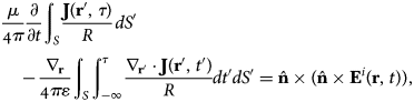
where R = |r−r′|, and the observation point r and the source point r′ indicate arbitrarily located points on the surface S. The variable τ = t−R/c is the retarded time, the parameters μ and ɛ are the permeability and permittivity of the surrounding environment, and  denotes an outward-directed unit vector normal to S at field point r.
To numerically solve (1), the induced surface current is approximately expanded by spatial vector basis functions fk(r) in conjunction with a complete orthogonal set of entire domain but causal temporal basis functions that decay to zero as t → ∞, i.e.,
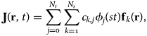
where φj(st) = e −st/2L j(st) are the weighted Laguerre polynomials and the scaling factor s controls the temporal support provided by the expansion [Reference Chung4]. The Laguerre polynomial of order j, L j(st), can be recursively generated from their lower orders [Reference Chung4]. The closed-form analytical expressions for the time derivatives and integration of (2) are available [Reference Geranmayeh, Ackermann and Weiland2]. Substituting (2) into (1) and then applying the temporal testing followed by spatial testing in Galerkin sense [Reference Ji, Sarkar, Jung, Yuan and Salazar-Palma5] give a recursive relation between different orders of the Laguerre polynomials,
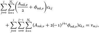
where



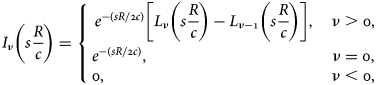
and ν = i−j. The discretized form of (3) is constructed and solved for first all m = 1, … , N s and then i = 1, … , N t. It should be noted that in the present new AMOD formulation (3), regardless of all previously introduced (A)MOD types, the summations over the contributions of all spatial sources ∑k are applied before the accumulations of the expansion orders ∑j. Assuming that all the lower orders of the expansion coefficients up to i−1 are known, they are moved to the right-hand side of (3) whereas the coefficients associated with the present order j = i are retained on the left side to establish such a following matrix equation:

III. SPACE CONVOLUTION PRODUCTS
The left-hand side of the TD EFIE (1) is the tangential component of the scattered field. Principally, J(r, t) is convolved by the Green's function to generate the scattered fields [Reference Geranmayeh, Ackermann and Weiland2]. The free space Green's function δ(t−R/c)/R and accordingly its time convolution with the weighted temporal expansion functions I ν(s(R/c))/R are translational invariant, i.e., they are a function of R mk = |rm−r′k|, the distance between the observation and source points. Therefore, when S is uniformly meshed, the dense and possibly asymmetric square matrices  can be represented only by their unique entries
 . In other words, the matrices
 are (Toeplitz)–block–Toeplitz, and hence, the matrix–vector products on the right-hand side of (8) are convolution products and they can be efficiently calculated via element-by-element multiplication in the spectral domain as
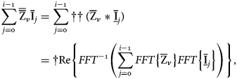
where  is a vector consisting of the unique entries of blocks in
 and the auxiliary vector
 is the flipped up/down and zero-padded extension of
 with the same size as
 . Operators †† and † extract only the desired entries of the product, namely †Re{} flips the resulting sequence in down/up direction and picks up the real parts of those array elements located corresponding to the positions of the original nonzero entries in
 . The same procedure is applied to the matrix–vector products of
 and
 in (8). The computational expenses of evaluating the double surface quadratures in the AMOD, namely (6) and (5), are relatively high. Hence, the compressed versions of
 ,
 with dimensions of O(N s), are stored in memory for further usage in constructing (8) through (9) and solving it for next higher orders of i. Besides, when symmetrical quadrature routines are used to numerically calculate the double surface integrals over non-overlapped source and observation subdomains in (5) and (6),
 reduces to
 , i.e., the number of unique entries N u halves and the cost of products may be further reduced.
To better explain fast computation of the spatial convolution products, we consider an inclined wire antenna modeled by a narrow strip, on which the current distribution has been approximated by N s+1 rectangular surface patches. Approximating the outer integrals in (5) and (6) by the value of the integrands at the center of observation patch,  find the following pattern:
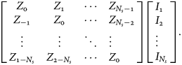
Thus,  and
 where N u = 2N s−1. As the second example, assume a tapered transmission line consisting two unparallel microstrips each paved with N s+1 rectangle subdomains defining N s rooftop basis functions, the associated portion of the impedance matrices forms two Toeplitz constellations as follows:
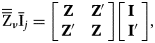
where the submatrices Z(′) and subarrays I(′), respectively, have the same structure as the asymmetric matrix and vector shown in (10). As a result,  and
 . The number of intermediately inserted zeros is N s−1, one less than the separation length of the Toeplitz blocks. For a parallelogram sheet partitioned by
 series of parallelogram patches whose corresponding edges have been numbered sequentially, the impedance matrices are (can be ordered in the form of) such four Toeplitz–block–Toeplitz submatrices,
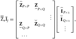
where P = N x(N y+1), Q = N xN y, and the two-level block–Toeplitz submatrices  ,
 ,
 , and
 contain repeated blocks of size N x × N x, each with pattern similar to that of (10) (Fig. 1). Therefore, the product of the four submatrices with the corresponding two subarrays can be obtained by (9) including four parallel FFT executions with respective lengths of
 ,
 , and
 . The remaining N y rows and columns as well as the rest down left corner of
 relating interactions with possibly non-uniformly meshed parts of the body are multiplied in the conventional way. Here, the rooftop edges are not indexed by canonical numbering along the two distinct directions, but rather to gain the block–Toeplitz characteristic for
 and
 additionally, the numbering of unparallel groups of edges is counted one group after the other. Identification numbers are assigned first to the all codirectional edges oriented in the larger dimension, that is the dimension with more divisions or so to say N x ≥ N y, excluding N y horizontal ending edges that are enlisted at the end. Thus, there is no need to transfer the plate geometry to the x−y plane, anchor its corner to the origin, and canonically number it in the y-direction as suggested by Yilmaz et al. [Reference Yilmaz, Weile, Jin and Michielssen10]. Of course,
 and
 parts of
 are zero due to the orthogonal orientation of spatial bases.
Positions of the unique elements of the submatrix  (P = 16, Q = 12) that may have been generated by a parallelogram plate (N x = 4, N y = 3) or inclined cylinder (N φ = 4, N z = 5) case studies. The second level of Toeplitz property has been highlighted by the dashed lines encompassing the blocks. The numbering of elements infers the calling sequence in constructing
 . Periodically N x−1 = 3 zeros are inserted between every N x consecutive current elements (level borders) to build
 .

Geranmayeh et al. [Reference Geranmayeh, Ackermann and Weiland15] proposed uniform discretization of cylindrical parts of the scatterer for proper local alignment of the surface normal vectors , e.g., modeling tube-like parts of the structure such as accelerator cavity arms, via interconnects, etc., by the rooftop bases. The sequential edge indexing of (inclined) cylinder parts with rotationally (a)symmetric cross sections directly renders interaction matrices containing Toeplitz–block–Toeplitz-shaped submatrice(s) associated to the mutual coupling of the rooftop bases on the tube parts. Considering that a tube is partitioned into N φ subdomains in azimuthal and N z subdomains in longitudinal directions, P = N φN z and Q = N φ (N z−1) in (12) and  ,
 , and
 . Here also
 and
 are zero. Figure 1 typically illustrates how the compression algorithm serially puts in order the unique entries of block aggregates to fill in
 for a resulting two-level block–Toeplitz submatrix.
In general case, according to the block–Toeplitz structure of the submatrices, zeros are first inserted at appropriate locations [Reference Barrowes, Teixeira and Kong12] into the reversed version of  so as to obtain the auxiliary current vector with proper alignment, suitable for direct convolution with
 . The auxiliary vector
 is then zero padded to the length of
 before the FFT and subsequent multiplication in Fourier domain. The convolution is readily accomplished in O(N s log N s) operations. The location of initially inserted zeros is then used directly to suppress the extra terms and recover the reconstructed product in the final step. Note that some algorithms, such as the one proposed by [Reference Hu, Chan and Xu8], only exploit the Toeplitz structure of blocks, rather the block–Toeplitz property in companion as explained here. In addition, we have shown that the present extended algorithm, inspired from [Reference Barrowes, Teixeira and Kong12], can also be applied to rectangular matrices
 and
 when P≠Q (Fig. 1).
IV. PERIODICITY AND MULTI-LEVEL TOEPLITZ MATRICES
Let S consist of duplications of a cell S 0 at regularly space positions with Dp centric spacing, where the integer p is the subsystem repetition label in alignment with the specific direction  . The interaction matrix elements can then be computed from (5) and (6) alternatively in local groups (p, q) by considering
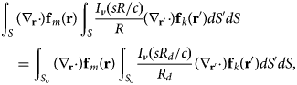
where  in which the variation range of the global coordinates r and r′ are confined to the primary subsystem S 0. The dependency on Dp−q substantiates a (additive) Toeplitz property in
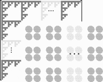
 when all identically ordered unknowns corresponding to the cells along are listed sequentially one after the other. Figure 2 exhibits the fractal-like pattern of the interaction matrices
 for a set of periodic non-uniformly meshed objects with four-level Toeplitz property on the fundamental blocks independent from the island meshing, two interior levels due to the inherent subsystem periodicity along x and y axes (n x = 2, n y = 2), and two additional outer levels owing to n yy = 3 and n xx ≥ 4 times n xn y-cell group replication along the y and x directions, respectively. Matrix–vector multiply can be computed using the FFT approach (9) in block-wise form, that is corresponding elements from every block are multiplied collectively, so as to scale the complexity to O(N t2N s2 (1/n xy) log n xy), where n xy = n xn yn xxn yy. The outermost corner subblocks (ending branches) in Fig. 2 are related to the far subsystems, and they may be approximated equally by the interaction of centric elements.
All (partially) filled square blocks are lined up corresponding to the distances between the (groups of) array elements. The matrix is fully dense and only the replicas of the original subblocks have not been depicted to reflect the shift invariancy (diagonal displacement) of the (sub)blocks on the four outermost nested Toeplitz levels.

Assuming that a 2-D periodic rectangular-shaped PEC patch (a capacitive mesh filter) with finite size of n xn y cells is meshed by n xn yN s 0 rooftop basis functions (where N s 0 = (N x+1)N y+N x(N y+1)), the submatrices in (12) are expanded to P = n xn yN x (N y+1), Q = n xn yN xN y. Resembling the former nested periodic case in Fig. 2, the encompassed block-wise Toeplitz property because of the periodicity can be concatenated to the every Toeplitz–block–Toeplitz interaction submatrices of the underlying uniformly meshed subsystemes in (12) when the periodicity effects are exerted in the most outer Toeplitz levels. Figure 3 illustrates how the periodicity along two different axes can be incorporated within the third and fourth levels of the four block–Toeplitz submatrices when the subsystems are composed of either of the generic case studies in Fig. 1. Dots in Fig. 3 specify the primal location of the required elements to be calculated and emplaced in  for the first quarter of the matrices. Starting from the down-left corner entry in every one of the four submatrices, among the unique elements, whose column and row indices are, respectively, greater and smaller than the others are emplaced prior to the rest in the auxiliary array sequence. This is equivalent to include only the elemental coupling of the basis functions while moving first toward the positive x-axis and then along y-axis in each cell and considering the mutual couplings between the primal cell and the repeated copies afterwards. To fill the auxiliary current vector
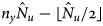
 , in transition to one higher level, different number of zeros has to be inserted between the corresponding current elements [Reference Barrowes, Teixeira and Kong12]. The three different stages happen between every N x, n yN x, and n xn yN x (that is every 4, 12, and 36) elements of the flipped current vector, where, respectively, N x−1,
 , and
 (in the example 3, 17, and 87) zeros have to be inserted in between. The obtained vector
 is finally zero padded up to the length n xn y
 u. Here,
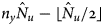
 denotes the greatest integer less than or equal to x. The first submatrix–vector product can be retrieved following the inverse FFT, once after every N x−1,
 , and
 elements of the flipped array, correspondingly N x, n yN x, and n xn yN x redundant elements are skipped.
Location of the unique entries in  when the mesh structure associated with Fig. 1 is repeated three and two times along different directions. The periodicity orders (n x = 2, n y = 3) are visible at the outer (third and fourth) Toeplitz levels. As many as the already picked entries in
 (the number of unique elements in the lower triangle part of the fictitious square box anchored to the level-border corner) intermediate zeros have to be inserted in
 once the up-right moving selection pointer jumps into another Toeplitz level.

Although for the ease of explanation, this paper frequently explicates the ordered selection of the unique matrix elements, no element picking-up procedure is to be developed in practice, rather the unique interactions of the basis functions are directly addressed for proper alignment in the auxiliary vectors and there is no need to build the complete (sub) matrices. In the phased array antennas, frequency-selective surfaces (FSS), photonic bandgap materials, artificial left-handed materials (metamaterials), etc., where the unit cell is composed of arbitrarily shaped patches, the auxiliary uniform meshes of the adaptive integral methods (AIM) [Reference Bindiganavale, Volakis and Anastassiu16] can be interrelated with the present algorithm. A similar principle can be applied to a 3-D uniform auxiliary grid [Reference Yilmaz, Jin and Michielssen17] that encases every scatterer cell as well as 3-D periodicity (an extra outer level with 2n z−1 inclusive blocks), which culminates the nested Toeplitz levels to six.
V. NUMERICAL RESULTS
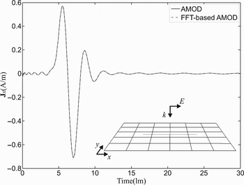
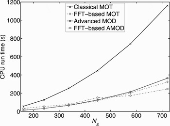
The incident field is a Gaussian-shaped plane wave with the full-width half-max of 0.7 light meter (lm). A flat 1 m × 1 m square conducting plate of zero thickness located in the x−y plain and centered at the origin is considered first. Six and five divisions are made along the x and y directions, respectively (N x = 5, N y = 4), which result in N s = 49 common edges. The governing TD EFIE (1) is solved by the AMOD with s = 3×10⁸ for N t = 80. Figure 4 shows the induced current at the middle of the plate. Continuing the marching process for the higher orders of Laguerre polynomials (N t > 120), the early ripples are totally vanished. As Fig. 4 illustrates, there is a good agreement between the results of the introduced AMOD scheme and its FFT-accelerated version in which every full matrix–vector multiplication is replaced by a convolution with a reversed vector, which is implemented through a double precision outer product in the Fourier domain. Considering the plate meshed with N x = 11, 13, …, 21 and N y = N x−1 divisions, the computing times of the marching process for the AMOD method up to N t = 80 and the MOT algorithm till N t = 100 are plotted in Fig. 5 versus the number of spatial unknowns. As seen in this figure, the MOD method benefits from the space-FFT approach more markedly than the MOT method does.
Induced surface current density at the center of the conducting sheet.

Average marching time in the AMOD and MOT methods versus the FFT-based counterparts in Fig. 4.

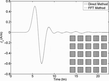
As the second example, a 0.5 m long hollow tube with radius 0.1 m is uniformly meshed by (N φ = 18, N z = 20) rectangular planar patches and is analyzed by the MOT scheme with N s = 666 rooftop bases for N t = 150. Figure 6 demonstrates that using the proposed algorithm for N gN t = 900 matrix–vector multiplications does not degrade the accuracy or perturb the late-time tranquilness of the response. Simulation results of 100-wavelength long strips also affirm that the algorithm (9) is aliasing free. Note that misalignment of even one entry during the FFT immediately causes explosion of the response amplitude. Figure 7 shows a 5×5 array of 1 m×1 m patches separated by 0.5 m. For the doubly periodic distribution of the antenna array, the algorithm exploits the block–Toeplitz structure of the interaction matrices in four nested levels to multiply all matrix–vectors by the FFT, n x = n y = 5, N x = 7, N y = 6, and N s = 2425. The four nested Toeplitz levels (while the outer two levels are dealt with the periodicity) totally reduce the computational effort to O(N t2N s log N s).
Transient electric current on the middle of the tube surface.

Current residing on the middle of the corner cell in the finite FSS consisting of a 5 × 5 array of plates.

VI. DISCUSSION AND CONCLUSIONS
Although the MOD schemes are the only approaches that thoroughly eliminate the late-time instabilities in numerical solution of field integral equations, the high computational expenses yet preclude their application in large-scale scattering problems. In this paper, a new formulation for the AMOD in conjunction with a parallelizable FFT-based algorithm with complexity of O(N s log N s) was proposed for accelerating the O(N t)N t retarded matrix–vector multiplications in the numerical solution of the TDIEs. Eventually, owing to the convolutional characteristic of the Toeplitz kernel, the current distribution was efficiently computed by O(N tN s log N s) operation cycles per iteration. The method is also a minimal memory with O(N tN s) storage demands because only non-redundant entries of the block–Toeplitz matrices are stored. The exterior multi-level Toeplitz arrangement due to the (multipath) periodical extension was incorporated into the deep block–Toeplitz structures relevant to the uniform meshing. This facilitates accurate analysis of large-scale periodic and partially periodic structure with finite size. The techniques presented in this work are directly usable for possible extension to the AIM (precorrected FFT) for fast analysis of irregular cell shapes. The temporal translation invariance can also be exploited for the MOD schemes similar to the spatial shift invariance [Reference Geranmayeh, Ackermann and Weiland18]. Most efficiently, the temporal translation invariancy can be adjoined to the aggregates of spatial Toeplitz matrices in an additional Toeplitz level above all the present levels. Since the algorithm does not benefit from symmetricity of the matrices, it can also be employed for fast numerical solution of the magnetic (and combined) field integral equations [Reference Geranmayeh, Ackermann and Weiland2].
 Amir Geranmayeh was born in 1980, in Tehran, Iran. He received a B.S. degree in electrical engineering and an M.S. degree (with distinction) in telecommunication engineering both from Amirkabir University of Technology (Tehran Polytechnic), in 2002 and 2005, respectively. From 2005, he is a Ph.D. candidate in electrical engineering and information technology at Darmstadt University of Technology, Darmstadt, Germany. Between 2001 and 2005, he served as a research assistant at National Center of Excellence in Radio Communications and Power Engineering, Tehran Polytechnic. In 2002 and 2005, he was a research engineer at the Iran Telecommunication Research Center (ITRC) and Niroo Research Institute, the leading research organizations of Iran Ministry of Information & Communication Technology and Ministry of Energy, respectively. In late 2005, he joined the Institut für Theorie Elektromagnetischer Felder, Technische Universität Darmstadt. His primary research interest is in applied computational electromagnetics. Mr. Geranmayeh was a recipient of full Deutschen Forschungsgemeinschaft (DFG) graduate research fellowship, honourably mentioned IEEE AP-S'09 student paper award, the IMS'09 and the European Microwave Association special travel grant, and the ITRC's grants for both B.S. and M.S. theses. He was also a nominee for the EuMC'08 young engineer prizes and the finalist of IEEE/ACES'05 student paper contest. He had an invited talk for Graduiertenkolleg “Physik und Technik von Beschleunigern”, in summer 2005.
 Wolfgang Ackermann received diploma and Ph.D. degrees in electrical engineering from Universität Siegen, Germany, in 1995 and 2002. From l995 till 1997, he worked for the interdisciplinary research project on “Deep Sea Mining” forming a cooperation between the electrical and mechanical engineering faculties at Universität Siegen. Since October 2002, he is with Institut für Theorie Elektromagnetischer Felder at Technische Universität Darmstadt, Germany, working as an assistant professor.
 Thomas Weiland was born in 1951. He studied electrical engineering and mathematics at Technische Hochschule, Darmstadt, Germany, and received a Ph.D. degree in 1977. As a fellow at European Institute for Nuclear Research (CERN), Switzerland, he began the first studies on EM simulation of relativistic particles in the time domain. In 1983, at Deutsches Elektronen Synchrotron (DESY) in Hamburg, he set up an international collaboration in order to develop the software package MAFIA for three-dimensional (3-D) EM and charged particle simulation. From 1989, he has been a full professor at Technische Universität Darmstadt, as well as the head of Institute for “Theorie Elecktromagnetischer Felder” (TEMF). In 1992, he founded CST GmbH, which is recognized as the market leader in 3-D EM time-domain technology. In 2003, he became the chairman of board of the newly founded research center “Computational Engineering” at the TU-Darmstadt. He was elected a member of the Academy of Science and Literature, Mainz, in 1992. He received the Physics Prize from the German Physical Society for his contributions to the field of scientific computing and the US Particle Accelerator School's Prize for Achievements in Accelerator Physics and Technology, both in 1986, the Leibniz Prize from the German Research Association in 1987. He won the Max Planck-Research Prize for International Collaboration in 1995, and was awarded the Philip Morris Research Prize in 1997 and an honorary professorship by the Tongji University, Shanghai, in 2004.