Introduction
Owing to the hazardous effects of ionising radiation, in radiation therapy, sparing of normal tissues is essential. To reduce the dose received in the normal tissues located around the target volume, the radiation beam should be blocked. Several techniques, such as the use of high-energy beams to spare skin effects and modulation of radiation beam, have been addressed to reduce the harmful effects of radiation on healthy tissues. Today, to protect normal tissues two different approaches are generally applied: Multileaf Collimators (MLCs)Reference Boyer, Ochran, Nyerick, Waldron and Huntzinger 1 – 5 and Cerrobend blocks.Reference Dawson, Kahler, McDonald, Kopecky and Gu 6 – Reference Taherkhani, Mohammadi, Saboori and Changizi 9
MLCs, as extra-accessories, are mounted in most of the modern medical linear accelerators’ (linacs) head. They are controlled by computers. They are introduced to radiation therapy in the early 1990s as a reliable replacement for manual beam-shaping blocks. The saving of treatment time, possibility of transfer of the treatment details, and providing a clean environmentReference Boyer, Ochran, Nyerick, Waldron and Huntzinger 1 , 5 , Reference Galvin, Smith and Lally 10 , Reference Jordan and Williams 11 are reported as the main advantages of MLCs. In contrast, as main disadvantages, MLCs are too expensive and treatment details should be transferred through a network. The average cost of a modern MLC and supportive software is about 50% of a conventional linac, which is not equipped with a MLC. Therefore, the use of conventional methods to protect Organs At Risk and normal tissues, especially in the developing countries, are generally provided using Cerrobend blocks. They are not expensive and they do not need to be supported by sophisticated software. The radiation beam can simply be shaped using a block cutter machine. Therefore, although MLCs, as the best substitute for Cerrobend blocks, are utilised, the Cerrobend blocks are still in use in the developing countries. Moreover, the lack of interleaf and intraleaf leakages, straightforward and non-time-consuming commissioning, and quality control tests can be addressed as the main advantages of Cerrobend blocks.Reference Palta, Yeung and Frouhar 3 , Reference Stasi, Baiotto, Palamara, Gabriele and Scielzo 4 , Reference Galvin, Smith and Lally 10 , Reference Butson, Yu and Cheung 12 – Reference Pasquino, Casanova Borca and Tofani 19 Furthermore, the penumbra regions shaped using MLCs are generally larger than those generated by Cerrobend blocks.Reference Boyer, Ochran, Nyerick, Waldron and Huntzinger 1 – Reference Stasi, Baiotto, Palamara, Gabriele and Scielzo 4 , Reference Pasquino, Casanova Borca and Tofani 19 – Reference Frazier, Du and Wong 27 Finally, whereas MLCs are used to shape high-energy X-ray beams, Cerrobend blocks are still used for shaping electron fields.Reference Wojcicka, Yankelevich, Werner and Lasher 28 – Reference Brualla, Zaragoza, Sempau, Wittig and Sauerwein 32 It has been shown that the height of Cerrobend blocks strongly depends on the main substances used in the structure, the temperature of block maker furnace and environmental conditions.Reference Brualla, Zaragoza, Sempau, Wittig and Sauerwein 32 In the current study, the impact of the height, width of Cerrobend blocks and beam characteristics on the distribution of relative radiation dose at the protected area is investigated.
Materials and methods
For high-energy photons, a Primus linac (Siemens Medical Systems Inc., Oncology Care Systems Group, Erlangen, Germany), established at the Mahdieh Radiotherapy & Oncology Center, Hamadan, Iran, was used. The linac produces a 6 and 15 MV beam with repetition rate of 200 MU/minute, with 1 monitor unit corresponding to a calibrated dose delivery of 1 cGy under the reference conditions. In addition, for 1·25 MeV gamma beam, a Cobalt-60 machine established in the Tajrish Hospital, Tehran, Iran, was utilised. Several circular Cerrobend blocks with different heights (80 and 95 mm) and diameters (2 and 3 cm) were prepared using commercially available materials and a block cutter machine (Par Scientific, Odense, SV, Denmark).
To investigate the relative dose distribution under the protected area, a scenario, shown in Figure 1, was designed. Kodak extended dose range 2 (EDR2) films (Eastman Kodak, Rochester, NY, USA) were sandwiched between RW3 water-equivalent material slabs (Goettingen White Water, PTW, Freiburg, Germany). The raw pixel values were then converted to dose values based on readings achieved from an ionisation chamber measurement after fortnightly dosimetry check. It has been shown that EDR2 radiographic films display a linear response to the dose for a wide range (0·5–500 Gy) and an acceptable energy independency.Reference Dogan, Leybovich and Sethi 34 – Reference Mohammadi, Bezak and Reich 37 To digitalise acquired data, the exposed radiographic films were processed using an automatic film processor (Gevamatic 110 Agfa-Gevarel, Agfa- Gevaert, Melbourne, Australia). The processed films were then scanned using a commercial film scanner (Scan maker. 9800XL, Microtek, Singapore).
Experiment scenario conducted to investigate the radiation dose distribution under the protected area.

The raw data were first converted to the dose values using a calibration curve obtained from the relationship of the dose and image pixel values. The relative dose distribution at the protected area was then evaluated using in-house codes written in MATLAB (MathWorks, Natick, MA, USA).
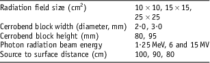
To achieve the results in detail, relative percentage depth dose, normalised to the maximum point in the irradiated fields, were extracted from dose distribution maps. The impact of several parameters, including radiation field size, the width and height of Cerrobend blocks, and the quality of the incident beam on the relative dose distribution for protected regions were evaluated. More details for the plan are shown in Table 1.
Variables evaluated for dose delivery assessment under protected area

Results and discussions
EDR2 film calibration for dosimetry tasks
To convert EDR2 films pixel values into the radiation dose (either relative or absolute values), the relationship between dose delivery and scanned films pixel values should be identified. Several EDR2 films were exposed on the reference condition (10 × 10 cm2, SSD = 100 cm and at D max using a 1·5 cm water equivalent build-up material) for a range of radiation doses from 0 to 500 cGy. The relationship between dose delivered to the films and pixel values were then applied to convert film raw pixel values to the dose. Outcome of the calibration is shown in Figure 2. Whereas the energy response of EDR2 films are reported to be linear for high-energy photon beamsReference Blackwell and Amundson 33 , Reference Devic, Seuntjens and Shanm 38 – Reference Burch, Kearfott, Trueblood, Sheils, Yoe and Wang 41 the same calibration curve was used for Cobalt-60 and 15 MV beams.
Calibration of EDR2 film for 6 MV beam. Abbreviation: EDR2, extended dose range 2.

Evaluation of Cerrobend block height on the relative dose distribution at protected regions
Typical relative two-dimensional (2D) dose distributions on the central axis for a radiation field with a different Cerrobend block height (80 and 95 mm), whereas other influencing factors including block width, source to surface distance (SSD), radiation field size and radiation beam energy are kept constant, are shown in Figure 3. The figure shows that an increase in the Cerrobend block height decreases the radiation dose at the protected area significantly. It can be estimated that the dose reduction with an increase of 15 mm Cerrobend block altitude can be observed in all depths. The maximum dose reduction was observed at depth of 5 cm from phantom surface.
Relative dose distributions measured using EDR2 films for a 10 × 10 cm2 radiation field, irradiated using a 6 MV photon, where the Cerrobend block diameter was 2·0 cm at SSD = 100. The Cerrobend block heights were (a) 80 mm and (b) 95 mm. The beam central axis is shown with a dashed line. Abbreviations: EDR2, extended dose range 2; SSD, source to surface distance.

It has been shown that an increase in the Cerrobend block height decreases the relative dose significantly. Iso-dose lines show that at the same condition, the distance between 5 and 10% dose lines, is significantly pronounced for shallow depths when Cerrobend block height increases to 15 mm.
2D dose distributions are not able to illustrate details for linear depth dose deposition. To explain the dose deposition clearly, a per cent depth dose profile was extracted from a protected area through the central axis of the beam for different Cerrobend block heights (these are shown in Figure 4). In the figure, the x and y-axes display depth and relative radiation dose, respectively. The dose depositions on shallower depths are found significantly different. With the increase in the depth up to the depth of 15 cm, owing to the increase in lateral scattering contribution, the difference decreases. After the depth of 15 cm, the relative dose difference remains constant.
The impact of the Cerrobend blocks’ height on the relative dose deposition under the protected areas through the central axis of the beam. The altitude of Cerrobend blocks were 80 and 95 mm for a 10 × 10 cm2 radiation field size and for a 6 MV photon.

Although, based on International Electro-technical Commission recommendations, 42 additive blocks and tertiary collimators are basically designed to reduce the dose to <5% of highest energy primary beam (∼5 HVL) at the normal treatment distance, the typical dose distributions and percentage depth dose normalised to the maximum dose delivered to the target areas shows that a 15 mm increase in the Cerrobend block decreases the dose deposited to the protected area around 3 and 7% at build-up and depth of 5 cm, respectively. For more safety and sparing the safety tissues, this can be easily translated to the clinics. For instance, for Paranasal sinus cases, where the eye lens is located in the radiation field, because of the dose constraints, the increase in the block height can be addressed as an essential action. However, because of the use of extra layer to block the radiation beam for high-energy photons, the electron and neutron contamination (for beam energies >10 MV) should also be considered.
The effect of Cerrobend block width on the absorbed dose at the protected areas
The impact of a block width on the relative dose distribution underneath the protected areas through the central axis of the beam is shown in Figure 5. With the increase in the width of a Cerrobend block, a significant decrease in the dose was observed at the protected area for all depths. Figure 5 shows that for large fields, an increase of a 1 cm diameter of a block approximately decreases 10% of dose at the protected areas. It can be concluded that very narrow Cerrobend blocks are not able to shield the areas supposed to be protected.
The impact of Cerrobend blocks’ width on the relative dose deposition under the protected area through the central axis of the beam. The width of Cerrobend blocks was 2·0 and 3·0 cm for a 25 × 25 cm2 radiation field size and a 15 MV photon beam.

It can be expected that with an increase of the width of protecting blocks, the dose on the central axis will be reduced because of the lack of scattered radiation reaching the protected areas. However, this study gives more details about the amount of the dose received in the protected area. Measurements show that with an increase in blocks width for 1 cm, a 10% dose reduction can be expected.
The effect of radiation field size on the dose deposited at the protected areas
The relative depth–dose curves versus the depth under the blocked area through the central axis of the beam are shown in Figure 6. As expected, with an increase in the radiation field size, the radiation dose received by the protected area is increased for all depths when high-energy photons were applied. In contrast, for the same procedure when a Cobalt-60 beam was applied, different results were observed. Figure 6b shows that up to depth of 12–13 cm beyond the surface of phantom/patient the dose deposition is identical for high-energy photons. In contrast, at deeper layers, the dose deposition for larger field sizes were found to be different compared with smaller field sizes.
The impact of radiation field size on the relative dose deposition under the protected area through the central axis of the beam for a range of radiation field sizes, for (a) a 15 MV beam, block height 80 mm and (b) for a Cobalt-60 beam and block height 95 mm. The diameter of the block was 2·0 cm for all measurements.

As the radiation field increases, the contribution of radiation dose, caused by the scattering, increases on the central axis of the beam. This justifies the results of depth dose deposition for high-energy beam. In shallower depths for a low-energy beam, here gamma rays from a Cobalt-60 source, the achieved results are the same as reported for higher energy beams. At deeper layers because of the absorption of scattered photons before reaching the central axis positioned under protected areas, the radiation dose decreases.
The effect of beam energy on the depth dose deposition at protected areas
The current study also evaluates the impact of the incident beam energy on the dose deposition at the protected areas for a range of available beam energies. The results are shown in Figure 7 for two different field sizes.
The impact of radiation beam energy on the relative dose deposition at the protected areas measured at the central axis of the beam for a 1·25 MeV, 6 and 15 MV photons for (a) 10 × 10 cm2, and (b) for a 25 × 25 cm2 radiation field. All measurements were taken using a 2 cm diameter and 80 mm height of Cerrobend block at SSD = 90 cm. Abbreviation: SSD, source to surface distance.

As Figures 7a and 7b show at all potential circumstances, an increase in incident photon energy significantly decreases the dose deposition to the blocked regions through the central axis of the beam. The maximum and minimum dose values deposited in the protected areas were found for Cobalt and 15 MV linac beam, respectively. As expected, with an increase in the depth, the radiation dose will be decreased for all energies. However, the dose deposition rate strongly depends on beam energy. For example, for a large radiation field (25×25 cm2), the maximum relative dose for Cobalt-60, 6 and 15 MV photon beams are found to be 37·4, 27·6 and 18·9%, respectively. This shows that the use of high-energy photons not only delivers a uniform dose to the target volume, but also the dose for the surrounding protected areas will be decreased.
The effect of SSD on the absorbed dose at the protected areas
The effect of SSD on the relative depth–dose curves on the area protected was also investigated. A percentage depth dose of the dose distribution through the central axis of the beam was extracted from film measurements for two different SSDs (these are shown in Figure 8). Results obtained from the current study show that a significant dose reduction reaching the protecting areas can be achieved with a decrease in SSD. The important thing is that dose difference is more than 10% and for a typical rectangular field when the SSD varies from 80 to 90 cm. Literature also shows that with the increase in the SSD, the dose will be increased.Reference Khan 8
The impact of source to surface distance on the relative dose deposition under the protected area through the central axis of the beam for a 6 MV beam and for a 10 × 10 cm2. Measurements are taken with a 2·0 cm diameter and 80 mm height of the Cerrobend block.

Conclusion
Cerrobend blocks are extensively used to protect healthy tissues in the developing countries. This study is an effort to provide more information about the dose distribution for protected regions based on a reliable 2D dose measurement using EDR2 films. Ionisation chambers and a scanning water tank are also able to produce line profiles. However, owing to the low spatial resolution for larger ionisation chambers and signal-to-noise ratio for smaller ones, as well as criticality of the set-up for protected areas, the film dosimetry can be addressed as one of the best available options for the current study.
Although the dose distribution can be predicted using treatment planning systems, owing to the lack of lateral electronic equilibrium, beam hardening and variation of the beam spectrum, they are not able to provide accurate information. In other words, even if Treatment Planning System (TPS) provides the dose distribution in a critical situation, one should verify the results using a reliable measurement.
On the basis of the results presented in the current study, it can be recommended that the Cerrobend block height can be increased from 70–80 mm (depending on departments’ protocol and vendor recommendations) to 90–95 mm. This reduces the dose at the protected areas significantly, especially for the small areas supposed to be shielded. However, electron contamination should also be considered with the increase in the height of blocks. Compared with low-energy photon beams, the use of higher energy photon beam reduces the dose at the areas protected.
Further studies are also recommended to find out the dose distribution predicted by treatment planning systems, especially for commercial dose calculation algorithms, and comparing with Monte Carlo modelling. In addition, on the basis of the information achieved, one can provide some simple rule of thumb to estimate the dose under the protected areas using Cerrobend blocks based on the width and height of a block, and radiation beam details, including beam energy and radiation field size.
Acknowledgement
The study was partially supported by the Hamadan University of Medical Sciences, Hamadan, Iran.