I. INTRODUCTION
Wireless personal area network (WPAN) systems in 60-GHz millimeter-wave band have been extensively studied, and 60-GHz WPAN standardization in IEEE 802.15.3c investigates both single carrier (SC) transmission employing frequency-domain equalization (FDE), which is called SC-FDE, and OFDM (orthogonal frequency division multiplexing) transmission because of indoor multipath channels [1–Reference Kato4]. Moreover, single-chip RF-CMOS ICs based on the silicon (Si) technology for the 60-GHz WPAN transceiver have been developed to reduce power consumption and cost [Reference Reynolds5]. However, the relatively large phase noise from the phase-locked loop (PLL) synthesizer occurs. In the 60-GHz SiGe BiCMOS chip, the phase noise of −85 to −90 dBc/Hz at 1 MHz offset was measured when the PLL synthesizers for the transmitter and receiver were cascaded [Reference Reynolds5]. Therefore, a single-chip Si CMOS transceiver requires a compensation method for the larger phase noise.
It is well known that OFDM is sensitive to the phase noise and frequency offset [Reference Pollet, Bladel and Moeneclaey6]. This is because the phase noise causes signal distortion in OFDM, which is characterized by common phase error (CPE), which induces a common phase shift at all subcarriers, and inter-carrier interference (ICI). In order to overcome this impairment in OFDM, several phase noise compensation methods have been proposed [Reference Dagres and Polydoros7, Reference Suyama, Suzuki, Fukawa and Izumi8]. Especially, as one of the lowest-complexity phase noise compensation methods with ICI cancelation capability, decision-directed phase noise compensation (DD-PNC) has been proposed for the 60-GHz OFDM transmission [Reference Suyama, Suzuki, Fukawa and Izumi8]. OFDM can suppress CPE by using pilot subcarriers inserted in each OFDM symbol, and the relatively exact tentative decisions can be obtained from the coherent detection. Thus, DD-PNC can compensate a time-domain received signal for the phase noise by exploiting decoded bits that a channel decoder calculates from the tentative decisions.
Similarly to OFDM, SC-FDE suffers from severe performance degradation due to the phase noise, and it has been investigated that SC-FDE is more affected than OFDM [Reference Zamorano, Nsenga, Van Thillo, Bourdoux and Horlin9]. In SC-FDE, it is difficult to compensate for the phase noise before FDE, and thus the time-varying phase noise in the FFT duration drastically causes ICI in the frequency-domain received signals after fast Fourier transform (FFT). Combining decision-feedback equalization (DFE) and the phase noise compensation for the SC transmission without FDE has been investigated [Reference Stark and Raphaeli10]. In addition, a phase noise suppression algorithm in single carrier-frequency division multiple access (SC-FDMA), which is also called DFT-spread OFDM, has been proposed [Reference Ryu, Kim, Ryu and Li11]. However, SC-FDMA can use frequency-domain pilots, and thus it employs the same phase noise correction using the pilots as OFDM. Therefore, these methods cannot be directly applied to the SC-FDE transmission in the 60-GHz WPAN system.
Moreover, a joint method of iterative block decision feedback equalization (IBDFE) and post-equalization carrier synchronization in SC-FDE has been proposed [Reference Araujo and Dinis12]. The method jointly compensates for the frequency offset and equalizes the received signal in an iterative manner, while it does not consider the phase noise and cannot prevent the error propagation in the decision feedback loop because it does not employ the channel coding. On the other hand, a combination method of turbo FDE (TFDE) and the post-equalization carrier synchronization, which copes with the frequency offset and the phase noise, has been proposed [Reference Sabbaghian and Falconer13]. It iterates TFDE with the decision-directed estimation for the unknown parameters by exploiting the log-likelihood ratio (LLR) of coded bits which the maximum a posteriori (MAP) decoder provides. These two combination methods can achieve a good performance under the relatively small phase noise condition, while the large phase noise drastically degrades the equalization performance of IBDFE and TFDE. This is because they cannot equalize ICI which the phase noise causes, and the residual inter-symbol interference (ISI) occurs in the FDE outputs. Hence, the post-equalization carrier synchronization, which uses the FDE outputs for the parameter estimation, cannot effectively operate in the 60-GHz SC-FDE transmission with the relatively large phase noise. In addition, TFDE requires the high-complexity processing such as the MAP decoding and calculating the mean and variance of the modulation symbol from LLRs, and the high-complexity method is not suitable for multi-Gbps transmission of the 60-GHz WPAN system because the realistic implementation is not available.
In order to provide an efficient, low-cost and reliable solution to the phase noise problem for the 60-GHz SC system, this paper proposes a SC-FDE receiver employing an iterative FDE and DD-PNC that can cope with multipath delay and phase noise for the SC transmission. In an initial processing of the proposed receiver, a cyclic prefix (CP)-based phase noise compensator (CP-PNC) removes the phase noise from the time-domain received signal before FFT by using CP, which is known to the receiver, and then the channel is equalized by the iterative FDE using the conventional minimum mean-square-error (MMSE) weight [Reference Benvenuto and Tomasin14, Reference Tuchler and Hagenauer15]. In an iterative processing, DD-PNC estimates the phase noise each symbol by exploiting the decoded bits of the decoder output, and then compensates the time-domain received signal for the phase noise by using the estimate. Since DD-PNC can remove the phase noise from the time-domain received signal before FDE, the iterative FDE does not have to consider the phase noise suppression, and thus the low-complexity iterative FDE that consists of the MMSE filtering and the residual ISI cancelation using the decoded bits can be introduced into the proposed SC-FDE receiver. Similarly to IBDFE and TFDE, the iterative FDE can outperform the conventional MMSE-based FDE (MMSE-FDE) by eliminating the residual ISI. In order to verify the effectiveness of the proposed SC-FDE receiver, computer simulations basically following both the 60-GHz WPAN standard and the one-pole/one-zero phase noise model proposed in IEEE 802.15.3c are conducted. The simulation results demonstrate that the proposed receiver with the iterative FDE and DD-PNC sufficiently removes the phase noise of −85 dBc/Hz at 1 MHz offset, and can realize the multi-Gbps transmission while requiring the low complexity in such a severe phase noise condition.
This paper is organized as follows. In Section II, the proposed SC-FDE receiver is explained briefly, and then transmitted and received signal models are derived along with the clarification of the phase noise problem. Section III describes the detail of the SC-FDE receiver employing CP-PNC and DD-PNC in addition to the iterative FDE. Section IV presents the computer simulation results in terms of packet error rate (PER) performance of the proposed receiver. Finally, some concluding remarks are given in Section V.
II. SC-FDE TRANSMISSION WITH DD-PNC
A) System model
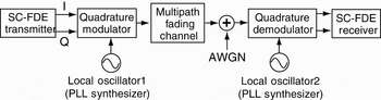
As shown in Fig. 1, a baseband SC-FDE signal is upconverted by a local oscillator, and a received signal through the multipath fading channel is downconverted by another local oscillator. Each local oscillator consists of the PLL synthesizer whose carrier frequency is assumed to be perfectly synchronized. However, the phase noise in the PLL synthesizer severely degrades transmission performance in SC-FDE. Note that this paper handles the phase noise only on the receiver side [Reference Pollet, Bladel and Moeneclaey6–Reference Sabbaghian and Falconer13], and that the carrier frequency offset is assumed to be negligible.
System model.

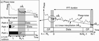
A block diagram of an SC-FDE transmitter in 60-GHz WPAN is shown in Fig. 2. The transmitter first adds the cyclic redundancy check (CRC) code to detect a decision error of the transmitted packet, and then it encodes information bits by the convolutional code. After interleaving the coded bits, it maps them into a modulation symbol, and CP is inserted. Note that as shown in Fig. 3, Golay code, which is known to both the transmitter and the receiver, is used as CP, and that another complementary Golay code is time multiplexed at the head of the packet as a preamble for the channel estimation [1].
SC-FDE transmitter.

Packet configuration.

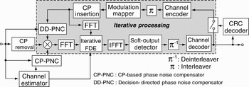
Figure 4 shows a block diagram of the proposed SC-FDE receiver employing the iterative FDE and DD-PNC. The receiver iterates the phase noise compensation and signal detection by exploiting an output of the channel decoder. In an initial processing, a channel estimator first estimates a channel impulse response by using the preamble, and then a CP-PNC removes the phase noise from the time-domain received signal by using CP of the Golay code and the channel estimates. After FFT converts the compensated received signal into the frequency-domain one, the iterative FDE performs the conventional MMSE-FDE [Reference Benvenuto and Tomasin14, Reference Tuchler and Hagenauer15], and then the output is transformed into the time-domain equalized signal by inverse fast Fourier transform (IFFT). Note that the iterative FDE does not employ the residual ISI cancellation in the initial processing because it cannot obtain the decoded bits. Next, the soft-output detector provides soft decision from the equalized signal, and after deinterleaving the soft decisions, a soft-decision Viterbi decoding is carried out. If a CRC decoder detects a decision error from the decoded bits, the receiver shifts the initial processing to an iterative processing. In the iterative processing, the receiver first generates a transmitted signal replica from the decoded bits. Next, DD-PNC recursively estimates the phase noise by the one-tap least-mean-square (LMS) algorithm using the replica, and then it removes the estimate from the time-domain received signal. After FFT, the iterative FDE, which consists of the MMSE filtering and the residual ISI cancellation using the decoded bits [Reference Benvenuto and Tomasin14, Reference Tuchler and Hagenauer15], is also performed for the compensated signal. The receiver repeats the iterative processing until the number of iterations exceeds a predetermined threshold or no decision error is detected.
SC-FDE receiver employing iterative FDE and DD-PNC.

B) Signal model
A received signal in the SC-FDE transmission with the phase noise is represented by an equivalent low pass model. Let N and Δt denote the number of FFT points and the sampling period which is equal to the symbol duration, respectively, and the number of symbols during the subblock, which consists of CP and data symbols as shown in Fig. 3, is equal to N. A sampled transmitted signal s i,k at the kth symbol of the ith subblock is given by

where c k is the Golay code with the length of N c samples, and z i,k is the kth data modulation symbol of the ith subblock. Its mean and variance are 0 and 1, respectively.
Furthermore, let h(τ) denote an impulse response of a D-path fading channel, and h(τ) is given using Dirac's delta function δ(τ) by
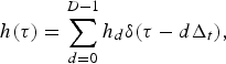
where h d and dΔt are a complex amplitude and a delay time of the dth path, respectively, and the maximum delay time (D−1) Δt is assumed to be less than N cΔt. Note that the fading fluctuation during one packet is assumed to be negligible.
The phase noise ϕ(t) at the time t = (iN + k)Δt is denoted by ϕ(t) = ϕi,k, and its mean and variance are zero and σϕ2, respectively. A sampled received signal r i,k is given by
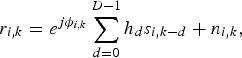
where n i,k is a sampled noise with zero mean and variance σn2. In addition, let us express e jϕi,k by using a sum of the mean  of the phase noise during the ith subblock and a remaining component Φi,k at the kth symbol from
 as

Then, r i,k can be written as

After FFT converts r i,k except those corresponding to CP, a received signal R i,n at the nth frequency component (0 ≤ n ≤ N − 1) is expressed as
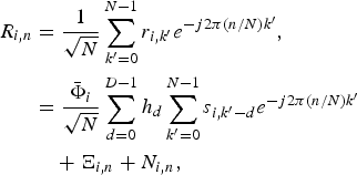

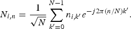
Ξi,n causes the performance degradation due to the phase noise. If the PLL synthesizer can reduce the phase noise to a sufficiently low level, i.e. Φi,k ≃ 0, Ξi,n does not occur.
Let S i,n denote the nth frequency component into which FFT converts s i,k, and S i,n is given by
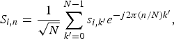
and the following term of (6) can be expressed using S i,n as
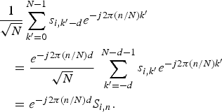
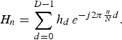
Hence, from (6) and (10), R i,n is given by

III. SC-FDE RECEIVER EMPLOYING ITERATIVE FDE and DD-PNC
A) Channel estimation
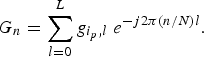
In the initial processing, the channel impulse response, which includes the phase noise, is estimated by using the preamble. The complementary Golay code a k, b k (±1, −N c ≤ k ≤ N − 1) has the following property:

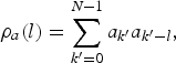
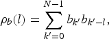
where 0 ≤ l ≤ N c. By calculating cross correlation between r i,k and the preamble consisting of a k and b k in Fig. 3, the channel estimator estimates g i p,l which is the complex amplitude of the lth path multiplied by the phase noise, and from (5) and (13), g i p,l is given by
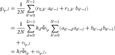
where  is the mean of the phase noise during the preamble. νi p,l is the estimation error that the phase noise and the noise cause, and is given by
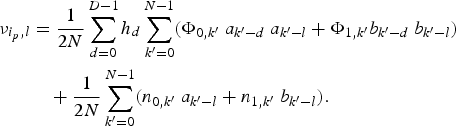
In order to improve accuracy of the estimation and estimate a normalized maximum delay L that CP-PNC requires, a path detector adaptively extracts the dominant paths from g i p,l. The path detector sets g i p,l to zero, if | g i p,l|2< α (σn2 + σ2ϕ), where α is a threshold parameter. After that, the maximum path index l that satisfies g i p,l > 0 is set to L. Let Ω denote the total number of extracted paths with g i p,l > 0 in the output of the path detector.
B) CP-PNC and MMSE-FDE
In the initial processing, CP-PNC estimates the phase noise using CP of the Golay code inserted at the head and the end of the subblock, and compensates the time-domain received signals for the phase noise by using the estimates. CP-PNC first generates a received signal replica  by using CP c k and the channel estimate g i p,l as
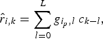
where −N c + L ≤ k ≤ −1, because the multipath delay causes the leakage of the data symbols from the (i−1)th subblock as shown in Fig. 5(b). Next, let ΔΦi denote the relative phase shift of  to Φi p, and the estimate of
 can be calculated based on the MMSE criterion that should minimize the cost function J ΔΦ given by
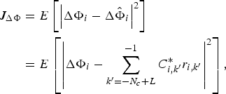
where E[ ] denotes an ensemble average, C i,k′ is the coefficient of the MMSE estimation, and the superscript * is the complex conjugate. Setting the gradient of J ΔΦ with respect to C i,k′ to zero, C i,k′ is given by

Phase noise compensation by CP-PNC.

The derivation of the above equation is based on the following approximation:

Hence,  can be estimated as

CP-PNC also calculates  of the (i + 1)th subblock, and estimates the relative phase shift
 at the kth data symbol by linearly interpolating
 and
 , and the estimate of ΔΦi,k,
 is calculated as

Finally, CP-PNC compensates the time-domain received signal for the phase noise by using  as

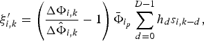
where  and ξ′i,kn is the residual phase noise component of the compensated received signal. FFT converts r′i,k into R′i,n as

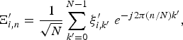
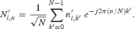
It is assumed that the phase noise can be perfectly removed from the received signal, i.e. Ξ′i,n≃0, and R ′i,n can be approximated as

Since the iterative FDE cannot obtain the decoded bits in the initial processing, and cannot perform the residual ISI cancelation, it operates as the conventional MMSE-FDE. Hence, MMSE-FDE equalizes R i,n′ based on the MMSE criterion. Let  denote the estimate of S i,n, and the cost function J S is defined as

where F n is a coefficient of the MMSE filter. Setting the gradient of J S with respect to F n to zero, F n is given from (29) by
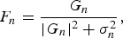
and thus the MMSE-FDE calculates  as
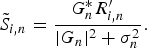
Note that MMSE-FDE cannot suppress the residual phase noise component Ξ′i,n because the derivation of F n ignores Ξ′i,n.
C) DD-PNC and iterative FDE
In the iterative processing, DD-PNC estimates the relative phase shift of the phase noise by the one-tap LMS algorithm, which minimizes a mean-square-error between r i,k and its replica [Reference Suyama, Suzuki, Fukawa and Izumi8]. DD-PNC first generates the received signal replica  excluding the relative phase shift of the phase noise by using g i p,l as
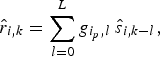
where  is a transmitted signal replica, and is generated by replacing z i,k of (1) with a data symbol replica
 that the iterative processing regenerates from the decoded bits.
Let w i,k* denote an estimate of the relative phase shift, and the received signal replica with the phase noise can be expressed as a product of  and w i,k* . Thus, an error signal e i,k between r i,k and the replica is given by

and the LMS algorithm recursively updates w i,k as

where μϕ is the step-size parameter in DD-PNC and a positive number [Reference Haykin16]. Note that an initial value of  is set to one. The above recursion is performed until the last sample of the ith subblock. After that, DD-PNC smoothes w i,k by backward exponentially weighting to improve the accuracy of the estimation, because the LMS algorithm is the forward recursion using the post-measured data and cannot exploit the future-measured data [Reference Kashima, Fukawa and Suzuki17]. Let
 denote a smoothed estimate, and
 is recursively updated as

Note that  . After smoothing w i,k,
 is normalized by
 because of | ΔΦi,k| = 1.
Finally, DD-PNC compensates the time-domain received signals for the phase noise by using  as
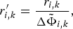
and FFT converts r′i,k into R′i,k.
The iterative FDE performs the MMSE filtering and the residual ISI cancelation using the decoded bits. The MMSE filtering and the residual ISI cancellation consist of the feedforward filter and the feedback filter, respectively [Reference Araujo and Dinis12, Reference Benvenuto and Tomasin14]. By using the coefficient F n of the feedforward filter and the coefficient B n of the feedback filter,  of the iterative FDE output is given by

where  is calculated by replacing s i,k of (9) with
 . Unlike IBDFE, the iterative FDE exploits S i,n, which is generated from the decoded bits for the residual ISI cancellation. The feedforward and the feedback filters are designed in order to maximize the signal to interference plus noise power ratio (SINR) of the iterative FDE output. Let ρm denote a correlation coefficient of
 in the mth iteration (m = 0, 1, …, M), and from (29) and (39), the feedback coefficient B n that minimizes the interference power is given by [Reference Benvenuto and Tomasin14]

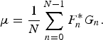
In addition, the feedforward coefficient F n that maximizes SINR is given by

and the residual ISI cancelation error depends on ρm [Reference Benvenuto and Tomasin14]. The iterative FDE employs the decoded bits instead of LLR, and cannot exactly calculate ρm from the variance of the modulation signal [Reference Araujo and Dinis12]. Hence, ρm is approximated to a real number that increases linearly with the number of iterations, i.e. ρm = m/M, which results in the complexity reduction [Reference Abe, Fujii, Suda and Tomisato18]. In the initial processing (m = 0), ρm = 0, and the iterative FDE uses the MMSE weight. In the Mth iteration of the last iterative processing, ρm = 1, and the maximum ratio combining (MRC) weight is used in addition to the residual ISI cancellation.
Although an inner loop of the iterative FDE that includes IFFT, the decision, the CP insertion, and FFT can repeat the MMSE filtering and the residual ISI cancelation in the decision feedback manner [Reference Benvenuto and Tomasin14], the proposed receiver does not employ the iteration in the inner loop. This is because the phase noise causes the severe performance degradation, and it can hardly be expected that only the inner loop improves the transmission performance. Hence, the proposed receiver repeats the iterative processing, which consists of DD-PNC, the iterative FDE, and the channel decoding.
The iterative FDE requires the scalar multiplication at each frequency component and FFT which generates  from
 . The total numerical complexity of the iterative FDE is O(N) per subblock, and the additional complexity for replacing MMSE-FDE with the iterative FDE is small.
D) Numerical complexity of CP-PNC and DD-PNC
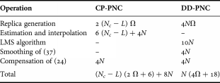
Table 1 summarizes the numerical complexity of CP-PNC and DD-PNC, that is, the number of the real multiplications per subblock in each iteration. CP-PNC first generates the received signal replica  using (18). Actually, the total number of extracted paths with g i p,l > 0 is Ω, and thus the replica generation in CP-PNC needs only 2 (N c − L) Ω multiplications. Next, CP-PNC requires 6 (N c − L) + 4N multiplications to estimate
 in (22) and (23). In addition, the number of multiplications of the phase noise compensation of (24) is 4N. Thus, the total number of real multiplications in CP-PNC becomes (N c − L) (2 Ω + 6) + 8N.
Numerical complexity of CP-PNC and DD-PNC.
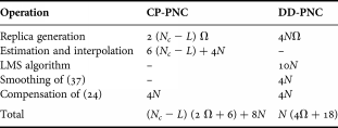
Moreover, DD-PNC needs 4NΩ multiplications for the replica generation, and the one-tap LMS algorithm in (35) and (36) requires 10N multiplications in the subblock duration. In addition, the number of the multiplications in the smoothing of (37) and the phase noise compensation of (24) are 4N and 4N, respectively. Hence, the total number of the real multiplications in DD-PNC becomes N (4 Ω + 18). For example, when N = 256, N c = 16, L = 12, and Ω = 5, the numerical complexities of CP-PNC and DD-PNC are almost 0.5 and 2.4 times as that of FFT, respectively. Therefore, the proposed receiver can achieve the phase noise compensation with low complexity.
IV. COMPUTER SIMULATIONS
A) Simulation conditions
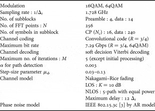
Computer simulations were conducted to verify the effectiveness of the proposed receiver under the simulation conditions listed in Table 2. Parameters of the SC-FDE transmission basically follow the IEEE 802.15.3c standard [1–Reference Kato4]. In addition to 16QAM, 64QAM was employed as the modulation scheme to achieve the higher bit-rate. The packet configuration consists of the four-subblock long preamble followed by 14 data subblocks. The number of FFT points N was 256, and the number of CP samples N c was 16. The convolutional code with the constraint length = 7 and the punctured coding rate R = 3/4 was employed. The maximum number of iterations was five. In the channel estimation, α for the path detection was set to 0.003. μϕ in DD-PNC was changed from 0.03 to 0.13, which increases linearly with the number of iterations. α and μϕ were optimized by the computer simulation.
Simulation conditions.

The channel model was five-path Nakagami–Rice fading with Ricean factor K = 10 dB, where K is defined as the power ratio of the line of sight (LOS) component to the non-line of sight (NLOS) one. The maximum delay in the multipath channel is 12Δt. Hence, L = 12 and Ω = 5, if the path detector can ideally extract the dominant paths.
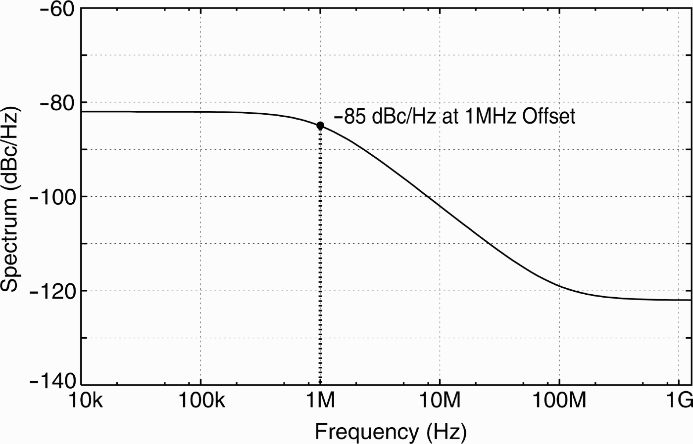
Furthermore, the power spectrum density (PSD) of the phase noise was the one-pole/one-zero model proposed in IEEE 802.15.3c as
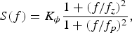
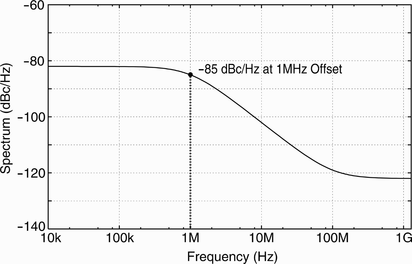
where K ϕ is the phase noise level that the loop filter determines in the low frequency, and f p and f z are pole and zero frequencies, respectively [Reference Choi, Shoji, Harada and Funada3]. Figure 6 shows PSD of the phase noise with K ϕ = −82 dBc/Hz, f p = 1 MHz, and f z = 100 MHz. The phase noise level was −85 dBc/Hz at 1 MHz offset, and the variance σϕ2 of the phase noise ϕi,k was 0.02 rad2. In the computer simulations, K ϕ was changed as a parameter, and the phase noise level was defined as PSD at 1 MHz offset. In addition, the phase noise was generated by the autoregressive (AR) model, where AR parameters can be calculated from the inverse Fourier transform of (43) [Reference Haykin16].
PSD of phase noise.
B) PER performance
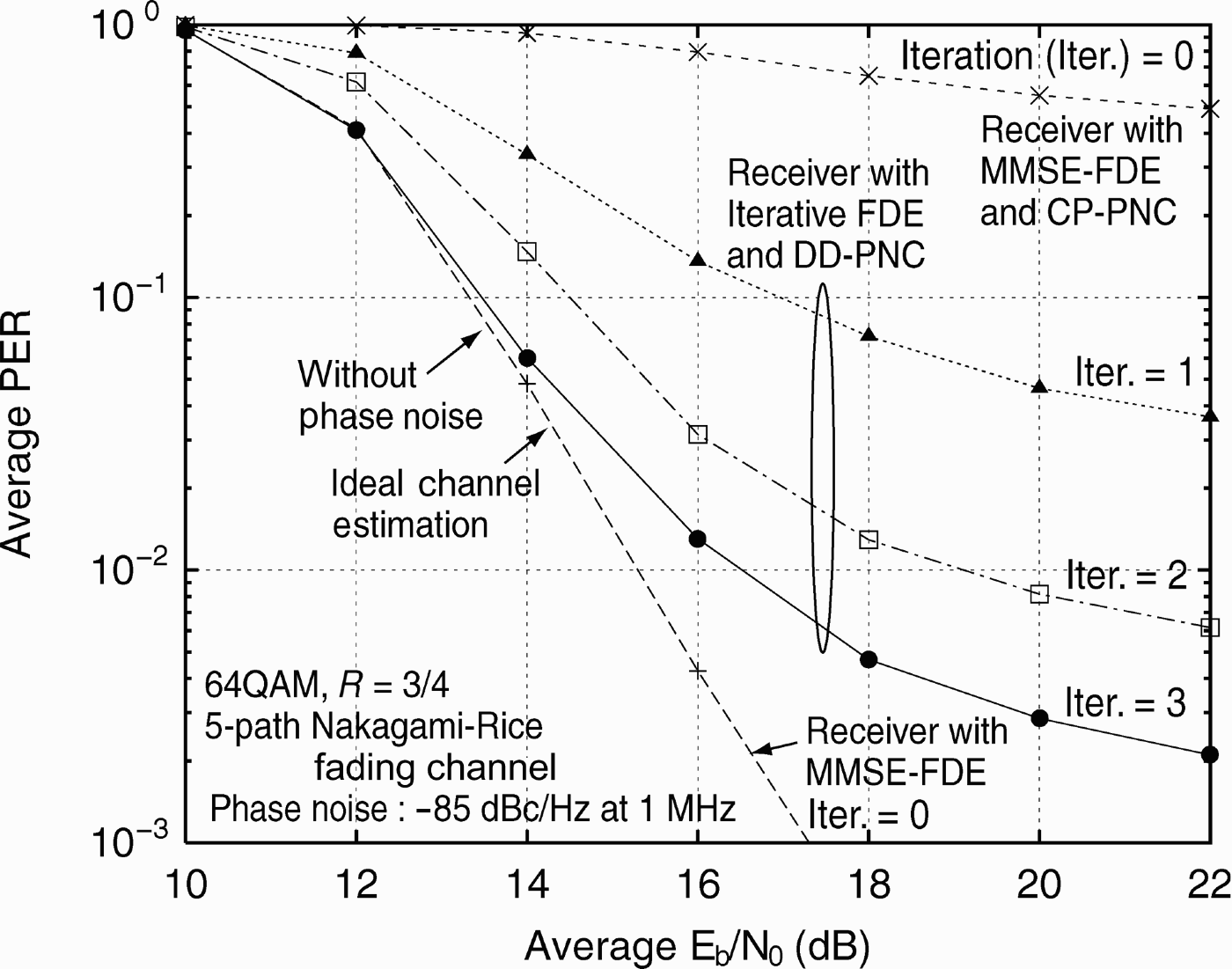
When the phase noise level is −85 dBc/Hz, average packet error rate (PER) performances of the proposed receiver with 16QAM and 64QAM are shown in Figs 7 and 8. For comparison, PER of the SC-FDE receiver with ideal channel estimation and MMSE-FDE under the phase-noise-free condition was also plotted (ideal performance). Figure 7 demonstrates that E b/N 0 degradation of the receiver with MMSE-FDE and CP-PNC at PER = 10−2 is 4.0 dB from the ideal performance, while one iteration of the proposed receiver with the iterative FDE and DD-PNC can achieve the same performance as the ideal performance, because it can remove the phase noise and obtain the diversity gain by the iterative FDE.
Average PER performance with 16QAM.

Average PER performance with 64QAM.
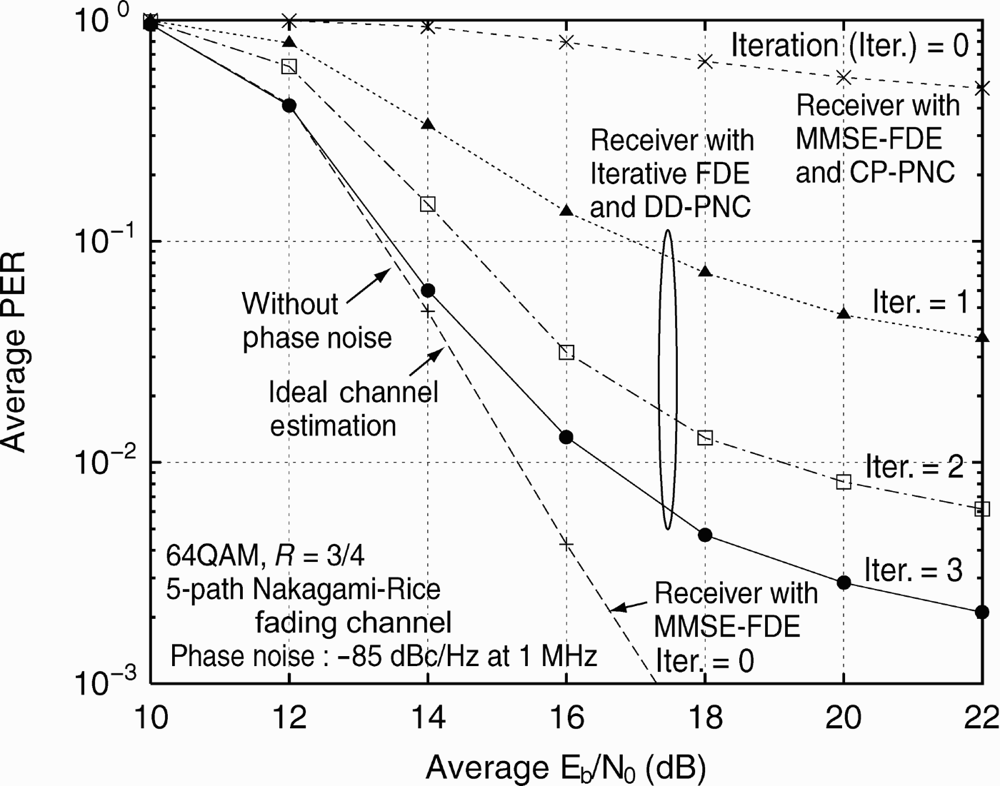
From Fig. 8, it is found that the phase noise severely degrades PER of the receiver with MMSE-FDE and CP-PNC, and that PER cannot reach 10−1 even in the high E b/N 0 region. On the other hand, the receiver with the iterative FDE and DD-PNC can achieve PER = 10−2 at the E b/N 0 = 16.5 dB by three iterations, and it can reduce the E b/N 0 degradation from the ideal performance to 1.1 dB. With 64QAM, the phase noise prevents the iterative FDE from getting the diversity gain.
C) Iteration performance with different phase noise levels
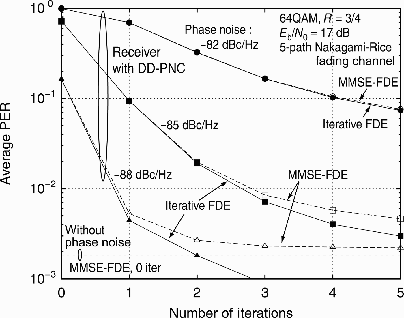
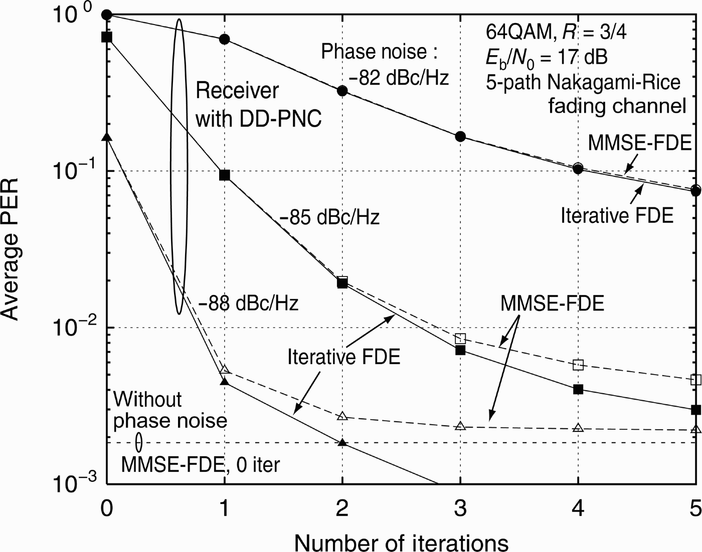
When the phase noise level is set to −88, −85, and −82 dBc/Hz, average PER performances of the proposed receiver with the iterative FDE and DD-PNC are shown in Fig. 9. The horizontal axis represents the number of iterations, and zero iteration indicates the initial processing. The received E b/N 0 was 17 dB. It can be seen that with −88 and −85 dBc/Hz, the proposed receiver can achieve PER = 10−2 by one and three iterations, respectively, while with −82 dBc/Hz, it cannot reach PER = 10−2 regardless of the number of iterations. When PER is less than 10−2, the proposed receiver with the iterative FDE and DD-PNC can achieve the better PER performance than the receiver with MMSE-FDE and DD-PNC [Reference Suyama, Onodera, Suzuki and Fukawa19]. It can be also found that with −88 dBc/Hz, two iterations of the proposed receiver with the iterative FDE is superior to the receiver with ideal channel estimation and MMSE-FDE under the phase-noise-free condition.
Iteration performance with different phase noise levels.
D) Effect of DD-PNC on different phase noise levels
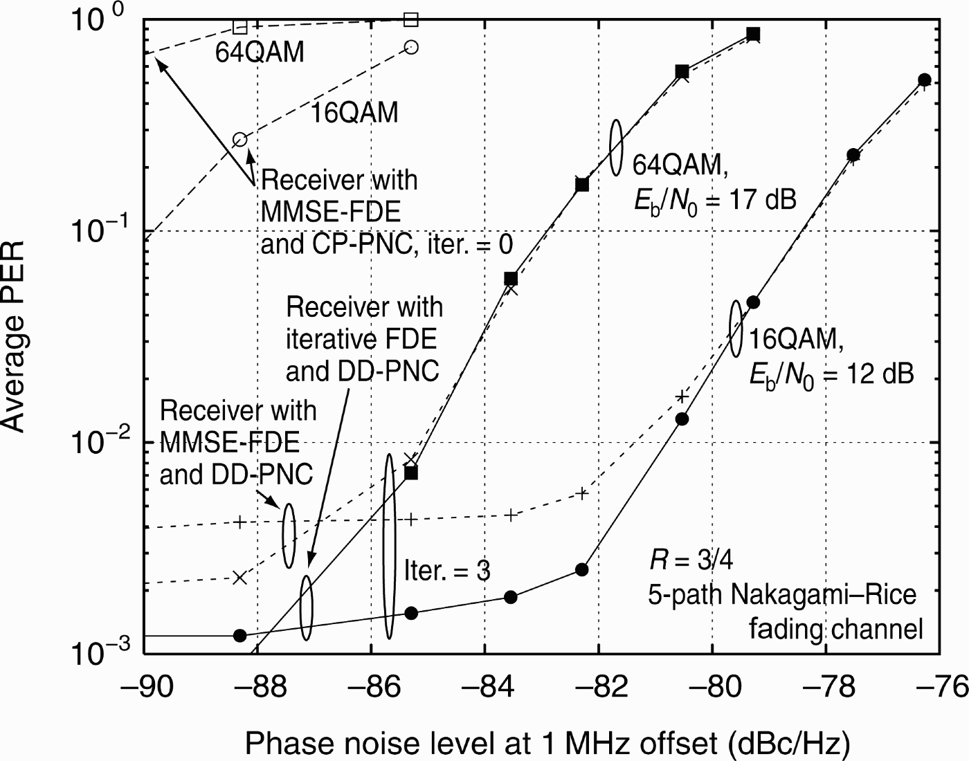
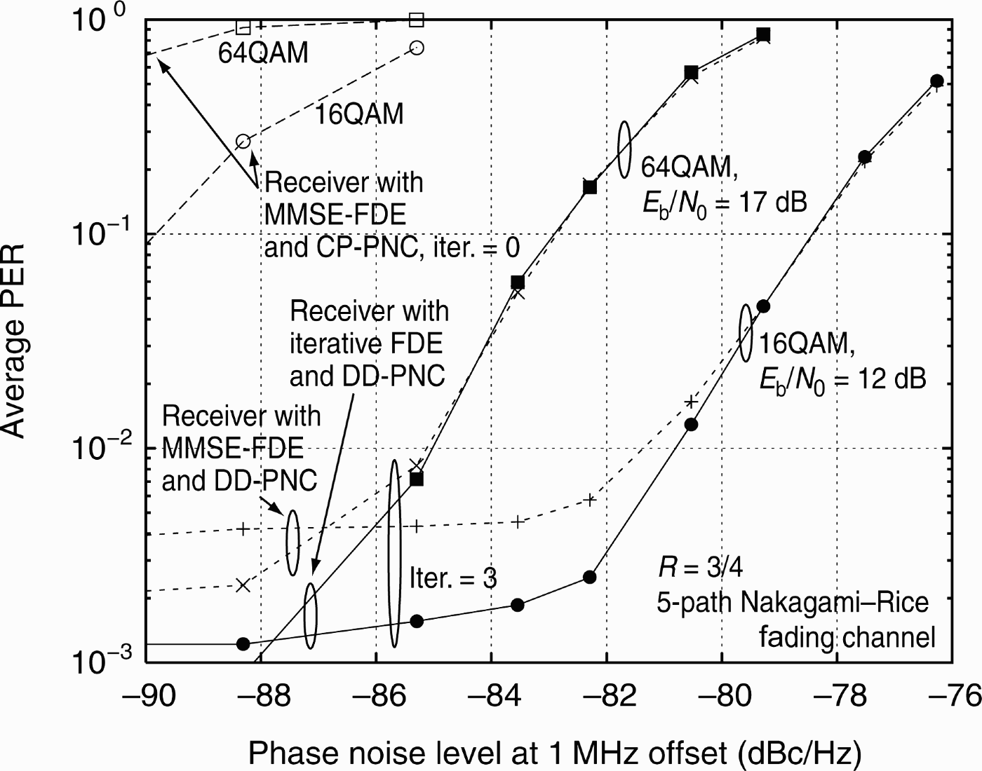
When the modulation scheme was 16QAM and 64QAM, average PER performances of the receiver with the iterative FDE or MMSE-FDE and DD-PNC are shown in Fig. 10. The horizontal axis represents the phase noise level at 1 MHz offset. The received E b/N 0 in 16QAM and 64QAM were set to 12 and 17 dB, respectively, and the number of iteration was three. This figure demonstrates that the performance degradation of the receiver with MMSE-FDE and CP-PNC is severe in 16QAM and 64QAM, while the receiver with the iterative FDE and DD-PNC can maintain PER = 10−2 with 16QAM and 64QAM until the phase noise level of −80.8 and −85.0 dBc/Hz, respectively.
Robustness of the proposed receiver with iterative FDE and DD-PNC against phase noise.
V. CONCLUSIONS
This paper has proposed the low-complexity SC-FDE receiver employing the iterative FDE and DD-PNC to alleviate the performance degradation due to the phase noise for the millimeter-wave SC systems. The proposed receiver repeats the iterative FDE and DD-PNC by exploiting the output of the channel decoder. In the initial processing, CP-PNC estimates the phase noise using the known CP, and it triggers DD-PNC in the iterative processing. DD-PNC estimates the phase noise by the one-tap LMS algorithm with smoothing, and can effectively cope with the phase noise by removing the estimate from the time-domain received signal. In addition, the iterative FDE can obtain the diversity gain by eliminating the residual ISI. The computer simulations have demonstrated that with 64QAM of R = 3/4, the phase noise with −85 dBc/Hz at 1 MHz offset drastically degrades PER of the receiver with MMSE-FDE and CP-PNC, while three iterations of the receiver with the iterative FDE and DD-PNC can achieve PER = 10−2 at the E b/N 0 = 16.5 dB. It has also been shown that with 16QAM, it can realize PER = 10−2 at the E b/N 0 of 12 dB until the severe phase noise level of −80.8 dBc/Hz at 1 MHz offset.
ACKNOWLEDGEMENT
This work was partly supported by “The research and development project for expansion of radio spectrum resources” of The Ministry of Internal Affairs and Communications, Japan.
 Satoshi Suyama received the B.S. degree in electrical and electronic engineering, the M.S. degree in information processing, and the Dr. Eng. degree in communications and integrated systems, all from Tokyo Institute of Technology, Tokyo, Japan, in 1999, 2001, and 2010, respectively. Since 2001, he has been an Assistant Professor in the Department of Communications and Integrated Systems at the Tokyo Institute of Technology. He is currently interested in various applications of the adaptive signal processing to radio signaling: turbo equalization, interference cancellation, and channel estimation for OFDM, MC-CDMA, and MIMO-OFDM. He is also interested in the implementation of the radio signal processing by DSP and FPGA. Dr. Suyama is a member of IEEE, the Institute of Electronics, Information, and Communication Engineers (IEICE) of Japan, and EuMA. He received the Young Researchers' Award from the IEICE in 2005, and the Best Paper Prize from the European Wireless Technology Conference (EuWiT) in 2009.
 Junichi Onodera received the B.S. degree in computer science and the M.S. degree in communications and integrated systems from Tokyo Institute of Technology, Tokyo, Japan, in 2007 and 2009, respectively. His research interest is phase noise compensation in OFDM and SC-FDE.
 Hiroshi Suzuki received the B.S. degree in electrical engineering, the M.S. degree in physical electronics, and the Dr. Eng. Degree in electrical and electronics engineering, all from the Tokyo Institute of Technology, Tokyo, in 1972, 1974, and 1986, respectively. He joined the Electrical Communication Laboratories, Nippon Telegraph and Telephone Corporation (NTT), Japan, in 1974. He was engaged in research on devices in millimeter-wave regions. Since 1978, he has been engaged in fundamental and developmental researchers on digital mobile communication systems. He was an Executive Research Engineer in the Research and Development Department, NTT Mobile Communications Network, Inc. (NTT DoCoMo) from 1992 to 1996. Since September 1996, he has been a Professor at the Tokyo Institute of Technology. He is currently interested in various applications of the adaptive signal processing to radio signal transmission: adaptive arrays, multiuser detection, interference canceling, and MIMO-OFDM for future advanced multiple access communication systems. Professor Suzuki is a member of IEEE and of the Institute of Electronics, Information, and Communication Engineers (IEICE) of Japan. He received the Paper Award from the IEICE in 1995, 2007 and 2009, the award of IEICE Fellow in 2006, and, Achievement Award in 2009 from IEICE.
 Kazuhiko Fukawa received the B.S. and M.S. degrees in physics, and the Dr. Eng. degree in electrical and electronics engineering, all from Tokyo Institute of Technology, Tokyo, Japan, in 1985, 1987, and 1999 respectively. He joined Nippon Telegraph and Telephone Corporation (NTT), Japan, in 1987. Since then, he has been engaged in research on digital mobile radio communication systems and applications of the adaptive signal processing, including adaptive equalization, interference cancellation, and adaptive arrays. He was a Senior Research Engineer at NTT Mobile Communications Network Inc. (NTT DoCoMo), from 1994 to 2000. Since April 2000, he has been an Associate Professor at the Tokyo Institute of Technology. Dr. Fukawa is a member of IEEE and the Institute of Electronics, Information and Communication Engineers (IEICE) of Japan. He received the Paper Award from IEICE in 1995, 2007 and 2009, and the Achievement Award in 2009 from IEICE.