I. INTRODUCTION
It is a critical problem to select an appropriate reinforcement material to enhance the physical properties of composites. Carbon nanotubes (CNTs) are one of the most promising nanomaterials in the area of advanced composites due to their remarkable thermal, electrical, and mechanical properties. Reference Iijima1–Reference Zhan, Kuntz and Mukherjee3 These outstanding properties are expected to contribute to improving the properties of composites. Therefore, many researchers have made significant effort to introduce CNTs in metal matrix composites, such as CNT/Mg, CNT/Al, and CNT/Cu. Reference Morelli, Yang, Couteau, Hernadi, Seo, Bonjour, Forro and Schaller4–Reference Kang, Park, Kim and Lee6 In contrast, relatively less attention has been paid on the CNTs reinforced Cu–W composites to improve their properties.
Cu–W composites have a lot of advantages such as high thermal and electrical conductivity, low coefficient of thermal expansion, and high mechanical properties, so these materials are widely used as electrical contacts, electroerosion segments, and heat sinks in various fields. Reference Liu, Xie and Qu7–Reference Gusmano, Bianco, Polini, Magistris and Marcheselli9 With rapid development of electronic industry, it requires the Cu–W composites to be higher physical properties, especially for the thermal conductivity. Therefore, addition of CNTs is predicted to enhance the properties of Cu–W composites, especially for the thermal conductivity because of the extremely high thermal conductivity of CNTs which is reported to be as high as 3000 W/(m K). Shi et al. Reference Shi, Yang, Shao, Duan, Yan, Xiong and Sun10 prepared Cu–W composites with CNTs as reinforcement and the thermal conductivity of composites improved 27.8% when 0.4 wt% CNTs were added. Some researchers explain this enhancement by the heat transfer mechanism at the interface of CNT–Cu, and suggest that the low interfacial thermal resistance will result in electron and phonon transfer smooth and that transfer will therefore improve the heat and electrical conduction. Reference Gao, Qu and Yao11–Reference Nan, Liu, Lin and Li13 Therefore, the interface between CNTs and the metal matrix plays a crucial role in determining the properties of composites. In addition, high level of entanglement is an obstacle to the uniform dispersion of CNTs, so their extraordinary properties are not apparent in the composites. Therefore, the other problem in the fabrication of CNTs reinforced composites is how to homogeneously disperse CNTs in the metal matrix.
Because of the importance of interface between CNTs and metal matrix, some researchers focus on the CNTs interface tailoring methods to modify the interface and to avoid the entanglement of CNTs in the metal matrix. For the typical functionalization process, CNTs are always treated by acids with high concentration to graft carboxylic (–COOH) and hydroxyl (–OH) groups. To achieve more wettability and sinterability with metal matrix, Chen, Reference Chen, Tu, Wang, Gan, Xu and Zhang14 Daoush, Reference Daoush, Lim, Mo, Nam and Hong15 Xu Reference Xu, Zhang, Cen, Xiang and Li16 have used Ni, Co, Cu, Pd coating CNTs to prepare CNTs reinforced metal composites which exhibited higher dispersity and physical properties. Nie Reference Nie, Jia, Jia, Li, Zhang and Liang17 found that W coating CNTs could obtain a uniform dispersion within the Cu matrix, and Ullbrand Reference Ullbrand, Cordoba, Ariztondo, Elizalde, Nygren, Aldareguia and Oden18 discovered that the adhesion between CNTs and Cu improved as the CNTs were precoated with Cr.
Clearly, physical properties would be enhanced by interface tailoring CNTs. It is not comprehensive, however, how the CNTs with interface tailoring can affect the physical properties of Cu–W composites at different CNT contents. In this paper, in an extended content of CNTs, dependence of physical properties on interface tailoring of CNTs has been addressed. The CNTs interface tailoring has been obtained through a process of acid functionalization and electroless plating. A particular emphasis has been placed on monitoring of microstructures of CNT/Cu–W composites as CNT contents increase, which is also affected by interface tailoring. As CNT contents increase, the question about whether the interface tailoring can really avoid the agglomeration has been solved as well.
II. MATERIAL AND METHODS
A. Material preparation
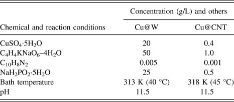
In this work, W powders with diameter of 10 μm were coated with Cu by electroless plating obtaining 20 wt% Cu@W powders. The compositions of plating solution and reaction condition are given in Table I. Multi-walled CNTs produced by chemical vapor deposition process, with diameter of about 10–20 nm and average length of 1 μm, were provided by Shenzhen Nanotech Port Co. Ltd in Shenzhen City, China. To fabricate Cu@CNT powders, CNTs were purified and functionalized in the acid solution mixture of H2SO4 and HNO3. Then the functionalized CNTs were cleaned with distilled water until the solution was neutral. After that, the CNTs were sensitized and activated with SnCl2·2H2O and PdCl2, respectively. The activated CNTs were dried by vacuum freeze drying. To get CNTs solution with homogeneous dispersion, the CNTs solution was ultrasonic for 10 min and infiltrated to remove CNTs agglomerations. Then the obtained CNTs solution was poured into plating bath and kept stirring. The composition of the plating solution and reaction conditions is given in Table I. Then activated CNTs were coated with Cu obtaining Cu@CNT powders which were dried by vacuum freeze drying. Cu@CNT and Cu@W powders were mixed together by ball-milling with speed of 210 rpm for 3 h, the volume fractions of CNTs in the CNTs/Cu–W composites varied from 0 to 2.0 vol%. Finally, the mixed powders were cold pressed into green compacts with diameter of 23 mm and sintered at 950 °C–100 MPa–2 h by hot-pressing in vacuum, and the heating rate was 10 K/min. The Cu–W composites prepared with Cu and W powders, CNT/Cu–W composites prepared with Cu@W powders, and raw CNTs were also fabricated for comparison.
Bath composition and operating condition of electroless plating Cu on W and CNTs.
B. Property measurement and microstructure characterization
The density of sintered compacts was measured by the Archimedes principle. Field-emission scanning electron microscopy (FE-SEM; Quanta-250, FEI Co., Hillsboro, Oregon) was used to evaluate the microstructure and fracture morphology of CNTs/Cu–W composites. X-ray diffraction (XRD; UltimaⅢ, Rigaku Japan Ltd., Tokyo, Japan) for phase analysis was collected. The thermal diffusivity was measured by the Laser Flash thermal constants measuring apparatus (TC-7000H, ULVAC Japan Ltd., Chigasaki, Japan) at room temperature in Ar atmosphere. And the thermal conductivity can be calculated based on the equation K = α·ρ·C p, where K, α, ρ, and C p represent thermal conductivity, thermal diffusivity, bulk density, and specific heat of the sample, respectively. The coefficient of thermal expansion (CTE) was measured (DIL 402C, NETZSCH-Gerätebau GmbH, Bavaria, Germany) in Ar atmosphere from room temperature to 350 °C. Scanning transmission electron microscope (STEM; JEM-2100F, JEOL Ltd., Tokyo, Japan) was used to characterize the interfacial bonding between CNTs and Cu. The bending strength (U.S. MT810 Ceramic test system, MTS Systems Corp., Eden Prairie, Minnesota) was tested in three-point bending on 20 mm × 6.25 mm × 5.25 mm bars with a crosshead speed of 0.5 mm/min. The reported bending strength was the average of three measurements. The electrical conductivity was measured by the four-point probe method on HL5500PC Hall effect measurement system (ACCEAT OPTICAL Corp., Denver, Colorado). All the tests were conducted at 25 °C except the mentioned testing temperatures.
III. RESULTS AND DISCUSSION
A. Preparation of Cu@W and Cu@CNT powders
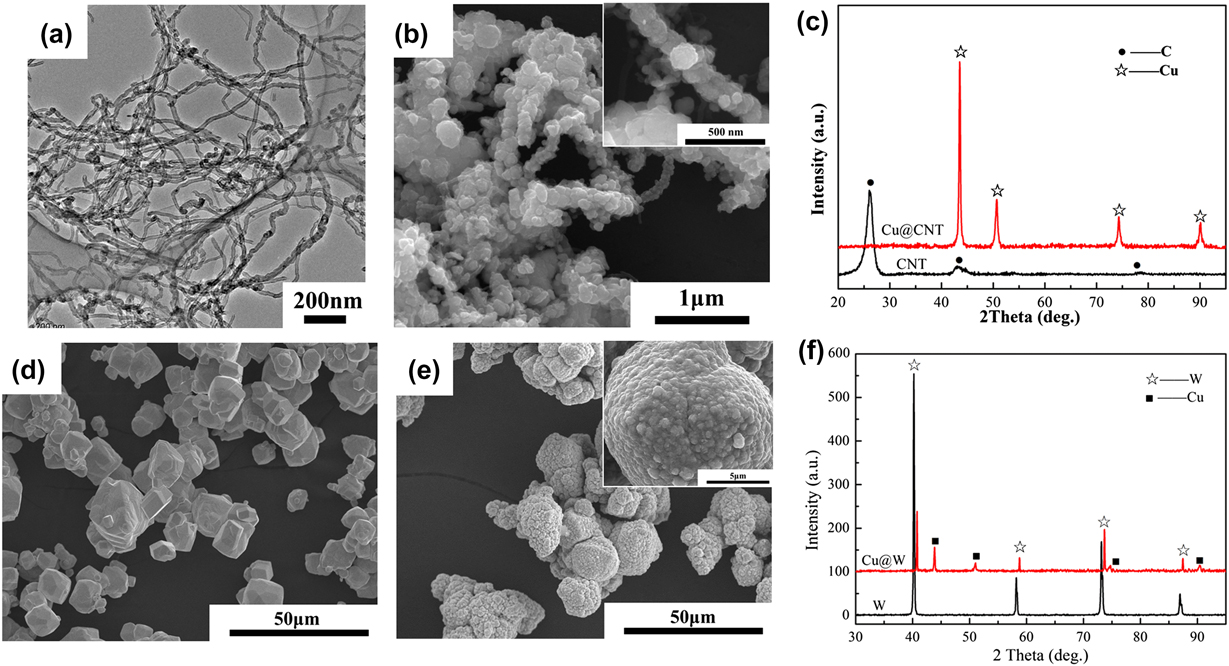
The Cu@CNT and Cu@W powders are prepared by electroless plating, the characterizations of both composite powders are shown in Fig. 1. CNTs distribute homogeneously after ultrasonic for 10 min. From Figs. 1(a) and 1(b), CNTs are densely coated with Cu and the diameter of Cu@CNT powders is about 100–200 nm which is much larger than that of raw CNTs (10–20 nm). The Cu particles grow like peas along the CNTs surface and connect with each other, as shown in the inset image in Fig. 1(b). Only Cu diffraction peaks are detected without C diffraction peaks for Cu@CNT powders in Fig. 1(c), because Cu has densely coated on the surface of CNTs. After CNTs are coated with Cu, Cu has covered densely on the surface of CNTs, and the Cu layer is more than 100 nm, so there is only Cu diffraction peaks for the Cu@CNT powders. As CNTs are activated with PdCl2, Pd nanoparticles are bonded at the surface of CNTs, which are the nucleaus for Cu particles growth during electroless plating. With reaction moving on, Cu particles grow big enough to connect each other. The excellent properties of CNT/Cu–W composites originate from the interface tailoring by Cu coating CNTs.
Characterizations of Cu@CNT and Cu@W powders: (a) TEM image of CNTs; (b) and (c), SEM, XRD of Cu@CNT powders; (d) W powders; (e) and (f) SEM, XRD of Cu@W powders.
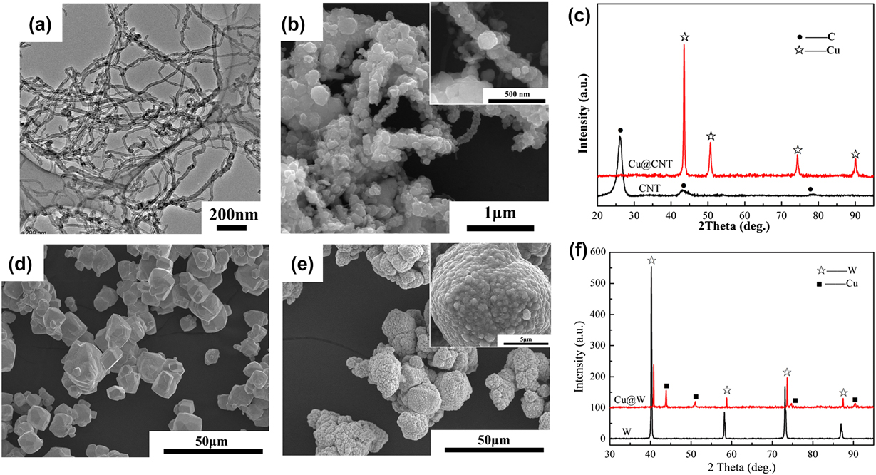
After electroless plating, W powders are coated with dense Cu layer and the sizes of Cu grains are about 200–300 nm from Fig. 1(e). Only W and Cu diffraction peaks are detected for Cu@W powders in Fig. 1(f), indicating that high purity Cu is coated on the surface of W powders. There is no CuO or Cu2O diffraction peaks in the XRD indicating that little Cu has been oxidized. The high purity Cu in the Cu@W powders is very useful to improve the thermal and electrical properties of composites. Furthermore, W powders are not activated in this work, indicating that W powders' surface is catalytic for the electroless deposition of Cu. So during the process of electroless plating, the Cu nucleates first at the surface of W powders. With the reaction moving on, the deposited Cu itself act as a useful catalytic agent, the Cu deposition reaction increases the thickness of the deposited Cu layer.
B. Thermal properties of CNT/Cu–W composites
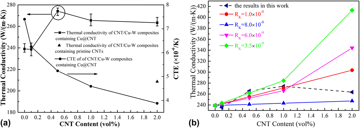
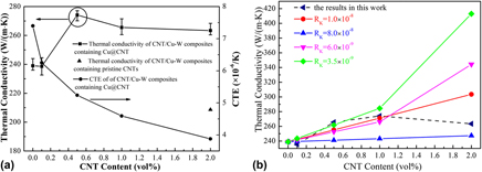
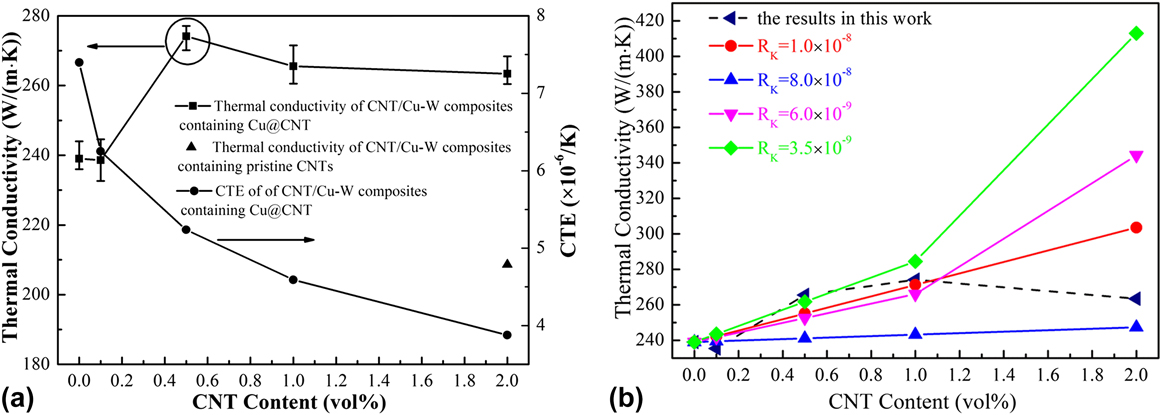
Figure 2 displays the thermal properties of CNT/Cu–W composites with different CNT contents. From Fig. 2(a), it is found that the thermal conductivity of the composites improves with CNTs increasing, and keeps above the value of Cu–W composites. The highest thermal conductivity of CNT/Cu–W composites achieves 274.1 W/(m∣K) with addition of 0.5 vol% CNTs, which is 15% higher than that of Cu–W composites without CNTs [239.0 W/(m∣K)]. It indicates that the addition of CNTs after interface tailoring has a positive effect on improving the thermal conductivity of the composites, which is agreement with the results in Ref. Reference Shi, Yang, Shao, Duan, Yan, Xiong and Sun10. On the other hand, the thermal conductivity of the pristine CNT/Cu–W composites is dramatically decreased which is roughly 68 W/(m∣K) lower than that of the CNT/Cu–W composites containing Cu@CNT powders. The results indicate that pristine CNTs do not play a role in the thermal conductance of the composites, and other factors affecting the thermal conductivity of the composites must be taken into account. Previous studies Reference Shi, Yang, Shao, Duan, Yan, Xiong and Sun10–Reference Nan, Liu, Lin and Li13 suggest that the thermal conductivity of CNTs reinforced Cu matrix composites is mainly influenced by the interface thermal resistance between CNTs and Cu, which will be discussed in the following paragraph. In contrast to the trend of thermal conductivity, the CTE of the composites gradually decreases with CNT contents increasing. The CNT/Cu–W composites with 2.0 vol% CNTs exhibit the lowest CTE of 3.87 × 10⁻⁶/K which is a half that of Cu–W composites without CNTs (7.39 × 10⁻⁶/K). The thermal properties confirm the possibility of exploiting Cu@CNT as a reinforcement phase to improve the thermal properties of Cu–W composites.
Thermal properties of CNT/Cu–W composites as function of CNT contents: (a) thermal conductivity and coefficient of thermal expansion; (b) interfacial thermal resistance.
Understanding the interfacial thermal resistance between the metal and CNTs is of primary importance in the study of the composite thermal properties. The presence of interfacial thermal resistance (R k) between CNTs and metal matrix is believed to be the main reason causing the measured thermal conductivity to be much less than expected. Reference Huxtable, Cahill, Shenogin, Xue, Ozisik, Barone, Usrey, Strano, Siddons, Shim and Keblinsk19,Reference Foygel, Morris, Anez, French and Sobolev20 So it is important to characterize the effect of R k on the thermal conductivity of CNT/Cu–W composites. The model used here to investigate the influence of R K on the thermal conductivity of CNT/Cu–W composites is proposed by Nan. Reference Nan, Liu, Lin and Li13 It is assumed that CNTs are distributed with a random orientation in the matrix for this model. The effective thermal conductivity of CNT-reinforced composites is given by the following equation:
 $${K_{\rm{e}}} = {K_{\rm{m}}}\left[ {1 + {{fp} \over 3} \cdot {{{{{K_{\rm{c}}}} \mathord{\left/ {\vphantom {{{K_{\rm{c}}}} {{K_{\rm{m}}}}}} \right. \kern-\nulldelimiterspace} {{K_{\rm{m}}}}}} \over {p + {{2{R_{\rm{K}}}} \over d} \cdot {K_{\rm{c}}}}}} \right]\quad ,$$
where K e, K m, and K c are the thermal conductivities of the composites, matrix and CNTs, f is the volume fraction of CNTs, p is the aspect ratio of CNTs, d is the diameter of CNTs, and R k is the interfacial thermal resistance. As the aspect ratio of CNTs is L/d, where L is the length of CNT, Eq. (1) can be simplified as:
 $${K_{\rm{e}}} = {K_{\rm{m}}}\left[ {1 + {f \over 3} \cdot {{{{{K_{\rm{c}}}} \mathord{\left/ {\vphantom {{{K_{\rm{c}}}} {{K_{\rm{m}}}}}} \right. \kern-\nulldelimiterspace} {{K_{\rm{m}}}}}} \over {1 + {{2{R_{\rm{K}}}} \over L} \cdot {K_{\rm{c}}}}}} \right]\quad .$$
Figure 2(b) shows the effective thermal conductivities of CNT/Cu–W composites with different R k values. In this work, Cu–W composites without CNTs are assumed to be matrix for the CNT/Cu–W composites. So according to references and present experimental data, the thermal conductivities of Cu–W “matrix” composites and CNTs are 239.0 and 3000 W/(m∣K), respectively. The mean length of CNTs in this work is 1 μm. Meanwhile, there are five sets of measured data of thermal conductivity {[f: 0.0 vol%, K e: 239.0 W/(m∣K)], [f: 0.1 vol%, K e: 235.4 W/(m∣K)], [f: 0.5 vol%, K e: 265.5 W/(m K)], [f: 1.0 vol%, K e: 274.1 W/(m∣K)], [f: 2.0 vol%, K e: 263.4 W/(m∣K)]} that can be fitted. As shown in Fig. 2(b), when CNTs fraction lowers than 1.0 vol%, the thermal conductivity is in good agreement with the estimated value as the value of R K is almost 3.5 × 10⁻⁹ m2 K/W which is much lower than that in CNT/polymer or CNT/ceramic composites of 2.9–8.3 × 10⁻⁸ m2 K/W. Reference Huxtable, Cahill, Shenogin, Xue, Ozisik, Barone, Usrey, Strano, Siddons, Shim and Keblinsk19,Reference Foygel, Morris, Anez, French and Sobolev20 This implies that some of the composites in this study achieve a structure with randomly well-dispersed CNTs. When CNTs contents are higher than 1.0 vol%, R k is deviation from the model, this may be the reason that CNTs agglomerate together which doesn't obey the assumption of the model.
C. Mechanical and electrical properties of CNT/Cu–W composites
Figure 3 shows the bending strength and electrical conductivity of CNT/Cu–W composites with different CNT contents. It can be seen that both the bending strength and electrical conductivity of CNT/Cu–W composites increase with CNT contents and reaches the maximum value of 989.8 MPa and 52.5% international annealed copper standard (IACS), respectively, when 0.5 vol% CNTs are added. Kim et al. reported that CNT–Cu composites have excellent strength because effective load transfer is produced at interface of Cu and CNTs. Reference Kim, Cha, Gemming, Eckert and Hong21 Therefore, as external stress is loaded on the CNT/Cu–W composites, some part of stress is absorbed by CNTs. Especially, there is bridging effect between CNTs and Cu particles leading to the high bending strength. Reference Daoush, Lim, Mo, Nam and Hong15 However, as the CNTs are higher than 1.0 vol%, there are CNT agglomerations in the grain boundaries which are the crack origins decreasing the bending strength, so the effect of enhancing bending strength of CNTs is counteracted by the CNT agglomerations. In addition, the Sn resulting from the sensitization process of CNTs could react with Cu and form intermetallics to decrease the bending strength of CNT/Cu–W composites.
Bending strength and electrical conductivity of CNT/Cu–W composites as a function of CNT contents.

The electrical conductivity in the composites is mainly influenced by the CNTs dispersity and interface between CNT and Cu. Therefore, due to the excellent interface of CNT–Cu, the electrical conductivity of CNT/Cu–W composites increases with CNT contents. After CNTs are more than 1.0 vol%, CNT agglomerations at the Cu grain boundaries increase the scattering of the charge carrier at grain boundary, hence reducing the electrical conductivity. And the intermetallics of Sn and Cu have lower electrical conductivity than Cu and decrease the total electrical conductivity of CNT/Cu–W composites. The similar results have been observed in other composites such as CNT/Ag composites Reference Wu, Wu, Ge, Zhang, Wang and Jiang22 and CNT/Cu composites. Reference Kim, Cha, Gemming, Eckert and Hong21 Therefore, CNT contents must be lower than 0.5 vol% to achieve high bending strength and electrical conductivity of CNT/Cu–W composites.
D. Mechanism of interface tailoring by Cu coating CNTs to enhance the properties of Cu–W composites
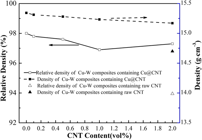
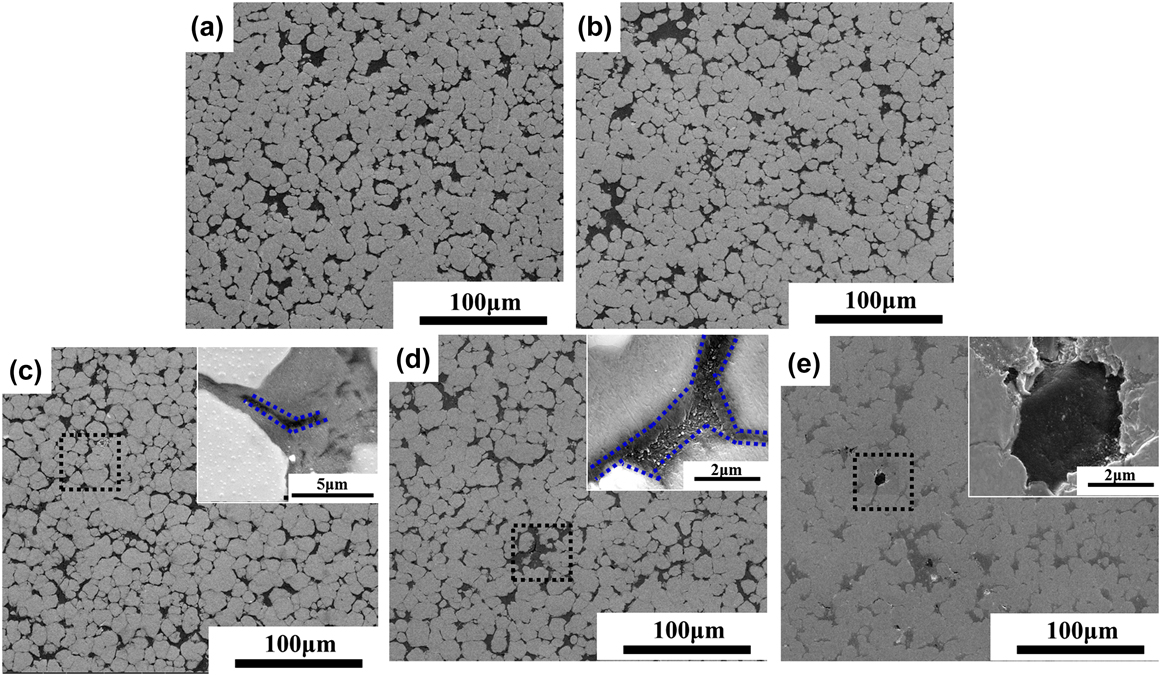
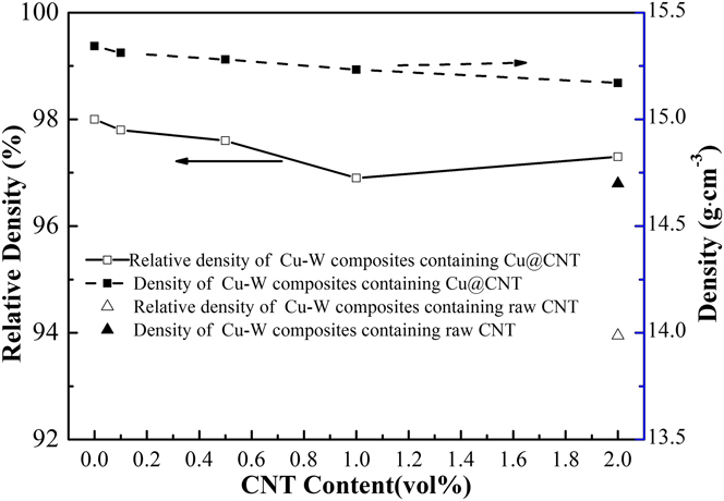
The relative density and density curves of CNT/Cu–W composites with different CNT contents are shown in Fig. 4. It can be seen that the relative densities of CNT/Cu–W composites are all higher than 97% and the density is higher than 15.1 g/cm3 when CNTs are coated with Cu, which is much higher than those of CNT/Cu–W composites added with pristine CNTs. As can be seen the corresponding microstructures in Fig. 5, CNT/Cu–W composites with different CNT contents are densified without any obvious pores. The CNTs are relatively uniformly dispersed in the composites when the CNT contents are lower than 0.5 vol%, as shown in Fig. 5(c). The electrical repulsive force between CNTs due to the functional groups causes homogeneous dispersion in aqueous solutions. So it enables to get uniform distribution of CNTs in Cu@CNT powders and subsequent CNT/Cu–W composites. With CNTs increasing to more than 1.0 vol%, there are some interparticle pores due to CNT agglomerations between W particles. When pristine CNTs are used, CNTs agglomerate more seriously, which the agglomeration size is larger than 2 μm. When CNTs are coated with Cu, the dispersity of CNTs is better than that of pristine CNTs in the Cu–W composites, and the sinterability between Cu and CNTs also improves. Therefore, compared with the relative density and microstructure of CNT/Cu–W composites added with pristine CNTs and Cu@CNT powders, it can confirm that Cu coating CNTs in prior to sintering is beneficial for improving the relative density of CNT/Cu–W composites and dispersity of CNTs, resulting in the high physical properties of CNT/Cu–W composites.
The relative density and density of CNT/Cu–W composites.
The microstructure of CNT/Cu–W composites with different CNT contents: (a) 0.0 vol% CNTs; (b) 0.5 vol% CNTs; (c) 1.0 vol% CNTs; (d) 2.0 vol% CNTs; (e) 2.0 vol% CNTs without coated with Cu.
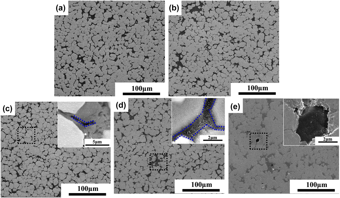
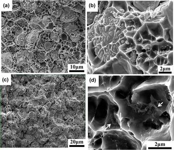
Figure 6 displays the fracture morphologies of Cu–W composites without and with CNTs after samples are tested with bending strength. It can be seen that the dominant fracture ways of Cu–W composites without CNTs are W particles fracture and Cu ductility fracture, the surfaces of W particles are covered with Cu network structure and the Cu dimples contain some small size W particles. The fracture morphologies of CNT/Cu–W composites added with 0.5 vol% CNTs are similar to that. The difference is that there are CNTs in the Cu dimples, as arrows shown in Fig. 6(d), some CNTs are pulled out from the Cu dimples. The fracture ways of CNT/Cu–W composites indicate that the bonding strength between CNT and Cu is strong, which is beneficial for electron transportation and stress transfer leading to the high thermal, electrical, and mechanical properties.
Fracture morphologies of CNT/Cu–W composites without and with CNTs: (a) and (b): Cu@W powders without CNTs; (c) and (d): 0.5 vol% CNTs.

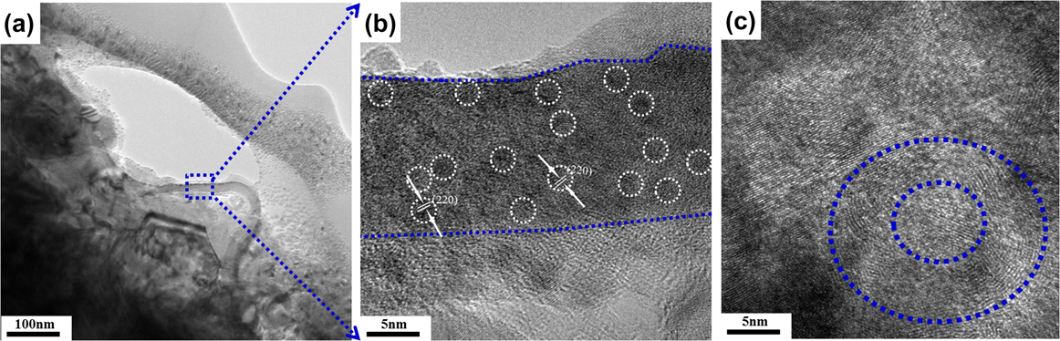
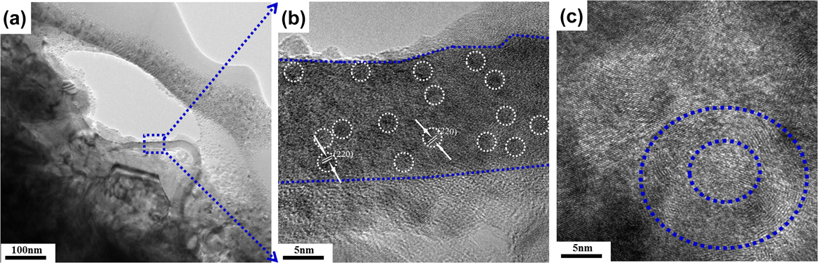
The transmission electron microscope (TEM) images in Fig. 7 give an insight into the influence of CNT–Cu interface morphology on the properties of the composites. It can be seen that individual CNT is closely implanted into Cu, and CNT has well contact with Cu without obvious defects such as gaps or intermediate compounds. Since the wettability and reactivity between Cu and graphite are poor, Cu and CNTs are proposed to be inactive. Reference López and Mittemeijer23 In the case of CNT composites with a reactive metal, such as CNT–Al, it is reported that Al4C3 was synthesized. Reference Estili and Kawasaki24 Though the formation of intermediate compounds is good to the sinterability of composites, it is adverse to the properties due to the intermediate compounds are generally brittle and low thermal and electrical conduction. Interestingly, there are some nano Cu particles at the CNT–Cu interface, as shown in Fig. 7(b). These nanocrystalline Cu grains are not homogeneously distributed, but tend to occur near the defect at the CNT–Cu interface. Based on these observations, it is likely that these defects potentially act as nucleation sites for Cu nanocrystalline grains. Therefore, a strong bond is formed between Cu and CNTs resulting in enhanced properties, such as high thermal and electrical properties as well as high bending strength of CNT/Cu–W composites.
TEM images of CNT/Cu–W composites with 0.5 vol% CNTs.
1. Effect of interfacial bond between CNTs and Cu
For the CNT/Cu–W composites, the enhancement of physical properties, including thermal, electrical, and mechanical properties, should be attributed to the good dispersity of CNTs and good interfacial bonding between Cu and CNTs. There are two main paths for heat and electron conduction in the CNT/Cu–W composites. The first path is Cu network mainly by electron conduction and the other one is through CNTs mainly by phonon conduction. The two paths are not separated completely and transform at the CNT–Cu interface in the heat conduction process. Therefore, due to the low interfacial thermal resistance R k, the thermal and electrical conductivity of CNT/Cu–W composites increases with CNTs contents. At the same time, the strong interfacial bonding between Cu and CNTs is also beneficial for the stress transfer to improve the bending strength. While the CTE reduction of the CNT/Cu–W composites can be attributed to the factors that CNTs have greatly low intrinsic coefficient of thermal expansion (CTE ≈ 0) as well as the homogeneous dispersity. The CTE is determined by the thermal expansion of metal matrix and the restriction of the reinforcement through interfacial effect. Reference Zhang, Wu, Jiang and Chen25 And the CNTs could inhibit the Cu grains growth, and decline the thermal expansion of Cu, which is also confirmed by Li. Reference Li, Misra, Horita, Koch, Mara, Dickerson and Zhu26 As shown in Fig. 6, there are many Cu nanoparticles inset into the sidewall of CNTs. With temperature increasing, a large content of interface between CNTs and Cu help to increase the restriction on Cu, then to decline the CTE of the composites.
2. Effect of CNT contents
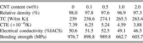
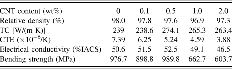
The physical properties of CNT/Cu–W composites, including the CNT contents, density, TC, CTE, and electrical conductivity have been summarized in Table II. After CNT contents are higher than 0.5 vol%, the physical properties of CNT/Cu–W composites considerably decrease. As mentioned previously, the contents drive the agglomeration of CNTs, which results in more defects in the composites. Similar results are obtained by Yamanaka, Reference Yamanaka, Gonda, Kawasaki, Sakamoto, Mekuchi, Kuno and Tsukada27 Shi, Reference Shi, Yang, Shao, Duan, Yan, Xiong and Sun10 and Cho. Reference Cho, Kikuchi, Miyazaki, Takagi, Kawasaki and Tsukada28 They reported that the reason for the decrease was related to the difficulty in dispersing the bundled CNTs with an increase in the CNT content. The high frequency tube–tube interactions are main reason for the lower thermal and electrical conductivity and the formation of CNT agglomerations also decreases the total contact area between CNTs and Cu, reducing the effective thermal and electrical transportation. Reference Cho, Kikuchi, Miyazaki, Takagi, Kawasaki and Tsukada28,Reference Zhang, Li, Yao and Chen29
The physical properties of CNT/Cu–W composites with different CNT contents.
IV. CONCLUSIONS
This article has provided a comprehensive study about the effect of CNTs interface tailoring on the physical properties of CNT/Cu–W composites.
-
(1) CNTs with interface tailoring showed superior dispersion state in the CNT/Cu–W composites. The homogeneous distribution of CNTs coupled with the formation of well-bonded CNT–Cu interfaces could effectively achieve thermal and electrical conduction and transfer load between CNTs and Cu in the CNT/Cu–W composites.
-
(2) The properties of the composites, including thermal properties, bending strength and electrical conductivity, improved with CNTs increasing. When 0.5 vol% CNTs were added, the thermal conductivity reached the highest value of 274.1 W/(m∣K). At the same time, the bending strength and electrical conductivity of CNT/Cu–W composites also achieved the maximum values of 989.8 MPa and 52.5%IACS, respectively.
-
(3) High CNT contents activated the agglomeration of CNTs in the composites and had a deleterious effect on the overall properties. The positive effect of interface tailoring of CNTs was counteracted by the CNT agglomerations.
ACKNOWLEDGMENTS
This work has been supported by National Natural Science Foundation of China (51572208) and the 111 Project (B13035).