Introduction
The tremendous improvement in ultra-wideband (UWB) technology has received great attention because of several attractive features, such as high data transmission, low power utilization, etc., since after the approval of an unlicensed band of 3.1–10.6 GHz by the Federal Communication Commission (FCC) [1]. As an essential component of the UWB system, antennas have drawn excessive deliberation in global research communities. Consequently, the designing of antennas for UWB communications needs to support wide impedance bandwidth in the cost of portability and good radiation characteristics. Hence, a printed antenna is, therefore, considered as the best choice to achieve portability but fails to attain broad impedance bandwidth [Reference Balanis2]. Therefore, designing UWB antennas with wider impedance bandwidth and compact size is highly desirable. For attainment of these features, different monopole UWB antenna configurations have been studied and investigated [Reference Palaniswamy, Kanagasabai, Kumar, Alsath, Velan and Pakkathillam3–Reference Ray, Thakur and Deshmkh6]. Although UWB antennas are providing wide impedance bandwidth but these antennas suffer from multipath fading effect. Therefore, to overcome the effects of multipath fading, multiple-input multiple-output (MIMO) technology comes into existence which uses multiple antenna elements in both transmitting and receiving ends without utilizing any additional transmitted power [Reference Ren, Hu, Yin and Fan7, Reference Singhal8]. Furthermore, this technique increases the channel capacity and spatial diversity gain (DG). Besides the advantages, MIMO antennas have low isolation due to the very close spacing among the antenna elements. Hence, to reduce the correlation coefficient various techniques were developed, which include placing parasitic stubs/strips between antenna elements [Reference Iqbal, Saraereh, Ahmad and Bashir9, Reference Malekpour and Honarvar10], defecting the ground plane [Reference Niu, Zhang, Chen and Zhong11, Reference Wei, Li, Wang, Xing and Xu12], etc. A compact UWB-MIMO antenna is presented in [Reference Iqbal, Saraereh, Ahmad and Bashir9] which consist of a stepped radiator with a shared ground plane. Two F-shaped stubs have been used between antenna elements to have low mutual coupling around −20 dB. Malekpour et al. [Reference Malekpour and Honarvar10] have designed a dual port UWB-MIMO antenna consisting of two monopole radiators with a comb-line structure in the ground plane to achieve isolation of around −25 dB. Zhang et al. [Reference Niu, Zhang, Chen and Zhong11] have used periodic fractal and arc-shaped DGS for achieving a maximum mutual coupling reduction of −22 dB. Similarly, periodic U-shaped DGS is proposed to reduce −10 dB mutual coupling between antenna elements [Reference Wei, Li, Wang, Xing and Xu12]. Although, the UWB-MIMO antennas have the capability of reducing the effects of multipath fading but it fails to filter out the interference of coexisting narrow band frequencies from the designated UWB frequency band. Hence, to reject the interfering bands, several techniques have been utilized over the last few decades. The most common way to achieve notched band functions is by incorporating various types of slots over radiator or ground [Reference Li, Chu, Li and Xia13–Reference Gao, He, Wei, Xu, Wang and Zheng15]. Lin et al. [Reference Mengyuan and Zengrui16] have designed a 4 × 4 UWB-MIMO antenna comprising a rectangular patch with an I-shaped slot and a C-shaped slot for realizing dual-notched behaviors in the frequency range of WiMAX (3.3–3.8 GHz) and WLAN (5.15–5.35 GHz) bands. Similarly, based on quasi-self-complementary (QSC) elements, four-port UWB-MIMO antenna is designed with single-band rejection at the WLAN band [Reference Aquil, Sarkar and Srivastava17] using slit cuts above the radiating patch. The notched band characteristics can also be realized using parasitic stubs near the radiator or feed line [Reference Tang and Lin18–Reference Liu, Cheung and Yuk20]. Zhu et al. [Reference Zhu, Li, Feng, Deng and Yin21] have designed two QSC antennas with WLAN band rejection by defecting bent slit in the radiating patches. However, all these techniques [Reference Li, Chu, Li and Xia13–Reference Zhu, Li, Feng, Deng and Yin21] have their own limitations in notch-width controlling capabilities and the radiation performance also degrades due to the defects in the antenna structure. Therefore, to improve the overall performances with the rejection of interferences, the electromagnetic bandgap (EBG) structures have recently being used over antenna circuits [Reference Modak, Khan and Laskar22, Reference Yazdi and Komjani23]. A defected ground compact EBG (DG-CEBG) structure has been used by Jaglan et al. [Reference Jaglan, Kanaujia, Gupta and Srivastava24] to attain dual notch behavior at WiMAX (3.3–3.6 GHz), and WLAN (5–6 GHz) bands. A 4 × 4 UWB-MIMO antenna with band rejection at 5.5 GHz is presented [Reference Kiem, Phuong and Chien25]. The notched band function is obtained by implementing two mushroom-type EBG structures near the feed line and isolation of −15 dB is achieved by using a rectangular stub.
The reported MIMO designs [Reference Li, Chu, Li and Xia13–Reference Zhu, Li, Feng, Deng and Yin21, Reference Jaglan, Kanaujia, Gupta and Srivastava24, Reference Kiem, Phuong and Chien25] are based on 2D type structures and the overall dimensions are also larger. Hence, to miniaturize the antenna structure researchers are mainly focusing on 3D type structures by vertically placing antenna elements [Reference Bilal, Saleem, Abbasi, Shafique and Brown26–Reference Srivastava, Kanaujia, Dwari, Kumar and Khan28]. A cuboidal miniaturizes four-element UWB-MIMO antenna is reported in [Reference Bilal, Saleem, Abbasi, Shafique and Brown26] which provides an isolation of −20 dB. Premlatha et al. [Reference Premalatha and Sheela27] have presented a vertically polarized four-element UWB-MIMO antenna with the isolation of −16 dB. In [Reference Srivastava, Kanaujia, Dwari, Kumar and Khan28], a 3D cuboidal four-port UWB-MIMO antenna is presented. The antenna produces single-notched band characteristics using a U-shaped open-loop resonator and provides an isolation of −20 dB. Furthermore, to the best of authors' knowledge, unfortunately, the literature on cuboidal MIMO antenna is very much limited. Hence, a cuboidal quad-port UWB-MIMO antenna is presented in this paper. The proposed antenna has a compact size and is evolved from a single-port F-shaped UWB antenna. The single-port F-shaped antenna has possessed an impedance bandwidth of 7.6 GHz with WLAN rejection characteristics using a pair of spiral EBG unit cells over the ground plane. Furthermore, to achieve compactness in the antenna structure with system robustness and secure communications, the single-port UWB antenna is modified with a four-port UWB-MIMO antenna by vertically placing each element between polystyrene foam to solve the problem of orientation mismatch between transceivers. The performance characteristics within all ports are observed to be identical. Beside this, the reported structure provides isolation of more than −15 dB without using any decoupling structure.
Proposed antenna configurations
The geometrical description and the design process of quad-port UWB-MIMO antenna are discussed in this section. Figure 1 reveals the geometry of the proposed single band-notched UWB antenna. First, a rectangular-shaped patch antenna (Ant-1) considering W = 8 and L = 7 mm with partial ground plane is designed over an FR4 Epoxy substrate material using equations (1)–(5) [Reference Balanis2], as depicted in Fig. 2(a). However, it failed to satisfy the criteria of the specified UWB frequency range. Now to attain wide impedance bandwidth, Ant-1 is modified by vertically truncated rectangular slots on the bottom edge of the patch referred to as Ant-2 (see Fig. 2(b)). Unfortunately, Ant-2 dims to produce the desired operational bandwidth. Furthermore, to achieve better impedance matching within the desired UWB frequency range, Ant-2 is modified by introducing a bent-shaped conductor on the top of patch (see Fig. 2(c)). Moreover, incorporation of bent-shaped conductor provides uniqueness in the antenna geometry:


Now, to predict the behavior of radiating element, lower cut-off frequency for Ant-3 has been roughly obtained using the standard equation (6) given for the printed rectangular monopole antenna [Reference Ray29]; here, T1 and R1 are the length and width of the patch, “P” is the gap between ground and patch and K = $\surd \varepsilon _{reff}$ :

where r = R1/2π.
Suggested antenna geometry: (a) top view and (b) bottom view.

Step-wise design: (a) Ant-1, (b) Ant-2, (c) Ant-3, (d) Ant-4, and (e) Ant-5.

Now, to reject the unwanted interferences within the UWB band, the Ant-3 is modified by placing a pair of spiral EBG unit cells over the ground plane which is referred to as Ant-4 (see Fig. 2(d)), which possesses a very compact dimensions of 12 × 19 × 0.8 mm3. The other optimized dimensions (mm) are as follows: LS = 19, WS = 12, h = 0.8, Wp = 2.25, C 1 = 2.5, Lp = 4.5, Wf = 0.6, Lg = 5, g = 0.3, L 1 = 2.3, L 2 = 1.92, W 2 = 0.19, CL = 21.4, T1 = 9, R1 = 11, and P = 2.5.
Once the desired requirements are achieved, the reported Ant-4 is further modified into a cuboidal four-port UWB-MIMO antenna by accumulating four antenna elements vertically wrapped around the polystyrene foam substrate material (ɛr = 1.2) to achieve overall compactness of the system. Generally, in planar MIMO antenna systems there is a restriction of antenna size, due to the placement of multiple antenna elements over the same plane. Simultaneously, the isolation among them also reduces. Thus, non-planar MIMO antenna systems have the benefits of miniaturize antenna structures over the planar counterparts. In addition to that, a 3D MIMO antenna also provides good spatial diversity by making the communication system robust and secured [Reference Srivastava, Kanaujia, Dwari, Kumar and Khan28]. The proposed MIMO design consists of microstrip line feeds which are represented as Port-1, Port-2, Port-3, and Port-4, followed by four identical F-shaped UWB antennas, which are arranged vertically in a cuboidal pattern referred to as Ant-5 (see Fig. 2(e)). The performance behaviors observed within all ports are almost identical and provides an acceptable mutual coupling reduction. In general, MIMO antenna systems should have a common ground plane rather than separated ground plane, for proper interpretation of signal levels based on the reference level. Although separated ground plane provides good isolation, in a real system it is not practical [Reference Sharawi30]. However, in open literature several MIMO antenna designs with separated ground plane are readily available [Reference Singhal8, Reference Bilal, Saleem, Abbasi, Shafique and Brown26, Reference Srivastava, Kanaujia, Dwari, Kumar and Khan28, Reference Li, Hei, Subbaraman, Shi and Chen31, Reference Tang, Wu, Zhan, Hu, Xi and Liu32]. Hence, due to the vertical orientation and separation of each antenna elements in our suggested design, practically it is not feasible to have a common ground plane.
Parametric analysis and discussion
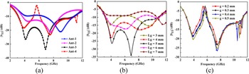
The simulated performance characteristics for Ant-1 to Ant-4 are compared in Fig. 3. Thus, Ant-1 with its arrangement is resonating at 9.0 GHz (6.7–10.8 GHz), meanwhile Ant-2 is operating over a wide range of 3.7–9.1 GHz. Finally, a wide operational bandwidth of 7.6 GHz (3.1–10.7 GHz) is realized in Ant-3 by modifying Ant-2 with a bent-shaped conductor. The calculated lower cut-off frequency for Ant-3 is also obtained at 3.05 GHz using equation (6). A parametric analysis concerning Lg (length of the ground) is performed to evaluate the performance characteristics of Ant-3. It can be seen from Fig. 3(b) that on increasing Lg from 3 to 5 mm, the antenna contributes to improving the impedance matching. However, it is also observed that at Lg = 6 and Lg = 7 mm, the antenna suffers from impedance mismatching resulting in the degradation of performance. Hence, Lg = 5 mm is considered as the optimized value.
Performance parameters: (a) comparison of Ant-1 to Ant-4, (b) parametric analysis of Lg, and (c) parametric analysis of g.

Now, Ant-3 is equipped with a pair of spiral EBG structures (see Fig. 2(d)) to obtain notched band characteristics at 5.6 GHz (WLAN band) as shown in Fig. 3(a). The EBG structures are placed over the ground plane aligning with the feed line. A parametric analysis with respect to “g” (gap between EBG structures) is performed to understand the occurrences of notched frequency. From Fig. 3(c), it can be seen that on increasing gap the coupling between EBG structure decreases resulting in a decreasing notch peak level.
Experimental validation
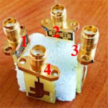
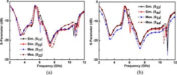
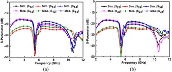
Finally, a cuboidal four-port UWB-MIMO antenna is designed using Ant-4 to attain diversity scheme and its fabricated prototype is shown in Fig. 4. Thus, to observe the effects on performances, suggested antenna (Ant-5) is simulated considering air as a dielectric medium between the antenna elements and it is noticed that the reflection coefficient curves for both the cases are similar within all ports. The simulated and measured |S 11| curve for the proposed quad-port UWB-MIMO antenna and its corresponding |S 22|, |S 33|, and |S 44| curves are illustrated in Figs 5(a) and 5(b) for comparison. It is obvious that on inserting multiple antenna elements the notched center frequency is shifted to 5.4 GHz, having an identical performance within all ports. Figure 6 displays the simulated and measured isolation curve for the reported four-port UWB-MIMO antenna. It is seen from Figs 6(a) and 6(b) that mutual coupling between Port-1 and Port-3, Port-2 and Port-4 is around −25 dB within the working frequency band. This is due to the opposite placement of antenna elements. However, isolation between Port-1 and Port-2, Port-1 and Port-4, Port-2 and Port-3, and Port-3 and Port- 4 is around −15 dB within the working frequency band of 3–5.5 GHz, because of adjacent placement of antenna elements. Moreover, a close agreement is observed between simulated and measured results, considering slight variation at upper frequency due to lossy substrate materials.
Fabricated prototype for the proposed four-port UWB-MIMO antenna.

Simulated and measured reflection coefficient curves for the suggested antenna: (a) |S 11| and |S 22| and (b) |S 33| and |S 44|.

Simulated and measured isolation curves for the suggested antenna: (a) |S 12|, |S 13|, and |S 14| and (b) |S 23|, |S 24|, and |S 34|.

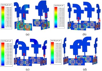
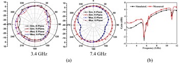
To validate the proposed antenna to be a MIMO antenna, certain parameters need to be calculated such as the envelope correlation coefficient (ECC) and diversity gain (DG). Moreover, these are the key parameters to ensure the performance of the MIMO antenna. The ECC can, therefore, be determined from S-parameters using the generalized formula presented in equation (7) [Reference Naji33]. Thus, in our proposed design, the ECC value is <0.2 within the working band except for 5–6.5 GHz as plotted in Fig. 7(a). The maximum DG of almost 10 dB is accomplished, except for the 4.8–6.5 GHz band (see Fig. 7(b)) which can be calculated using equation (8) [Reference Kumar, Urooj and Alrowais34]. Now, to understand the radiating mechanism of the antenna, the current concentration along the surface of the antenna is studied at notched frequency. Figure 8(a) shows the surface current distribution at 5.4 GHz when Port-1 is excited terminating other ports with 50 Ω matched loads. It can be seen that a strong current concentration is observed around the EBG structures; meanwhile, weak current concentration is observed on other ports. Similar behavior has also been observed when Port-2, Port-3, and Port-4 have been excited as shown in Figs 8(b)–8(d). The simulated and measured radiation patterns for the proposed quad-port UWB-MIMO antenna at two different resonating frequencies (3.4 and 7.4 GHz) are shown in Fig. 9(a). It is obvious that the antenna produces a fairly omni-directional radiation pattern in both planes. However, some fluctuation is observed in the measured result. Besides this, the antenna attains a maximum gain above 5.5 dBi at 10 GHz in both simulated and measured parameters as shown in Fig. 9(b). Finally, a comparison has been made between the existing literature studies in Table 1:


Simulated performance parameters: (a) ECC and (b) DG.

Simulated surface current density by exciting (a) Port-1, (b) Port-2, (c) Port-3, and (d) Port-4.

Simulated and measured (a) radiation pattern and (b) gain curve.

Comparison with the existing literature

Conclusion
In this paper, a cuboidal quad-port UWB-MIMO antenna has been designed and investigated. First, a single F-shaped UWB antenna is designed followed by single band-notched characteristics in the WLAN band. Hence, for achieving diversity performance it is modified with a four-port UWB-MIMO antenna by vertically placing the antenna elements. The impedance bandwidth obtained from individual antenna elements are almost similar (3.1–10.7 GHz) and having isolation of −15 dB between inter elements. The correlation between antenna elements are observed to be 0.2, except for the 5–6.5 GHz band. The realized ECC value is substantially smaller than the value of 0.5 being suggested for realizing the good diversity effect. Therefore, it is concluded that the suggested antenna has compact geometry with all the properties of the MIMO antenna.
Acknowledgement
This study was supported by the Science and Engineering Research Board (SERB), Department of Science and Technology (DST), Govt. of India (GoI) under a research grant No. SB/S3/EECE/093/2016.
 Sumon Modak received his B.Tech. degree in Electronics and Communication Engineering from Dr. MGR University (a Deemed University), Chennai, Tamil Nadu, India in 2015 and his M.Tech. degree with specialization in Communication System Engineering from Sambalpur University (SUIIT), Sambalpur, Odisha, India in 2017. At present, he is working as a Junior Research Fellow in a SERB-DST sponsored project in ECE department and also pursuing his Ph.D. in the same department at the National Institute of Technology Silchar, India. His current research interests include, ultra-wideband antennas, reconfigurable antennas, EBG structures, and neural networks applications in electromagnetics. He has published five research articles in the reputed journals of repute and conference proceedings. He is an active student member of IEEE, IEEE APS, and IEEE MTT.
 Dr. Taimoor Khan is an Assistant Professor in the Department of ECE at NIT Silchar since 2014. Prior to that, he has worked more than 15 years in several organizations. Also, he has worked as a Visiting Researcher at QU Canada during Sept.–Oct. 2019 and a Visiting Assistant Professor at AIT Bangkok during Sept.–Dec. 2016. His active research interests include printed antennas and microwave energy harvesting. He has successfully guided three Ph.D. thesis students and guiding six more students. He has published over 75 research articles in international journals and conference proceedings. He is executing three funded research projects including two international collaborative SPARC and VAJRA research projects with QU Canada and CSUN USA. He is an FIEI, FIETE, SMIEEE, and SMURSI. In Sept. 2020, he has been awarded a prestigious national IETE-Prof SVC Aiya Memorial Award. Also, he has edited a book titled Elements of Radio Frequency Energy Harvesting and Wireless Power Transfer Systems in Dec. 2020 published by CRC, USA.