1. INTRODUCTION
The performance of a Strapdown Inertial Navigation System (SINS) largely depends on the accuracy and timeliness of the initial state (Chung et al., Reference Chung, Lee, Park and Park1996; Fang and Wan, Reference Fang and Wan1996; Gao and Ben, Reference Gao and Ben2011; Tazarts, Reference Tazarts2011). Since other initial conditions such as velocity are relatively easy to acquire, we care most about the SINS body attitude with respect to the reference navigation frame during the alignment stage. The alignment procedure often consists of two consecutive stages: coarse alignment and fine alignment (Tang et al., Reference Tang, Wu and Wu2009; Wu et al., Reference Wu, Goodall and El-Sheimy2010; Wu et al., Reference Wu, Hu and Wu2006). The Kalman filtering-based fine alignment methods rely heavily on the coarse alignment stage to provide a roughly known initial attitude, otherwise they cannot guarantee a rapid and accurate alignment result (Silson and Simon, Reference Silson and Simon2010; Wu et al., Reference Wu, Wu, Hu and Hu2009; Wu and Pan, Reference Wu and Pan2012). A velocity integration formula based on an optimal method for alignment has been proposed in recent years (Silson, Reference Silson2011; Wu et al., Reference Wu, Wu, Hu and Hu2011; Wu and Pan, Reference Wu and Pan2013). It is considered to be a coarse alignment because the process only determines the attitude matrix without estimating the errors of the sensor, but it possesses the advantages of rapidity and can guarantee quite a high accuracy. If the velocity rate information is externally provided, a good coarse alignment could be obtained using the optimal approach which is an ingenious idea for the subsequent fine Kalman alignment.
Silson (Reference Silson2011) and Wu and Pan (Reference Wu and Pan2013) state that the proposed optimal method is a recursive alignment approach based on attitude optimization, the main idea of which is to take the initial attitude as a constant, and obtain the optimal initial attitude with the data of the IMU, then update the attitude from the initial to the current. The optimization-based alignment method, for the first time in the public literature, transforms the attitude alignment problem into a continuous attitude determination problem using infinite vector observations; the optimization approach is related to the so-called inertial frame method, more theoretically solid and more robust to disturbances and noise. However, some problems still need to be addressed. Theoretically more data is used in alignment. However, it should be noted that the output of the gyroscope/accelerometer includes many kinds of noise besides the true signal, not only random noise but also bias, rate drift ramp and quantization noise. A better inertial sensor means less noise. So if a type of integration algorithm can realize the alignment using a small piece of data segment, the accuracy of the alignment may be better than that of the alignment process using a long data segment due to the integration of bias. Unfortunately, it is not easy to achieve the task of alignment using too short a piece of data due to the random noise.
In this paper a new improved formula by decomposing the current attitude has been proposed. In the proposed method, a suitable but fixed length data segment is used to obtain the current attitude, which can restrain the influences of both the random noise and bias. The validity of the proposed method has been evaluated through the simulation and experimental studies.
2. REFERENCE FRAMES
Denote by n the local level navigation frame, an orthogonal reference frame aligned with north–east–down (NED) geodetic axes; by b the SINS body frame, an orthogonal reference frame aligned within the IMU axes; by e the Earth frame, an Earth-centred Earth-fixed (ECEF) orthogonal reference frame; by i the chosen inertial frame. The navigation rate equations expressed in the n-frame respectively are as follows:
 $$\dot C\hskip1pt_b^n = C\hskip1pt_b^n w_{nb}^b \times, \quad w_{nb}^b = w_{ib}^b - C\hskip1pt_n^b (w\hskip1pt_{ie}^n + w\hskip1pt_{en}^n )$$
 $$v^n = C\hskip1pt_b^n \hskip2ptf^b - (2w\hskip1pt_{ie}^n + w\hskip1pt_{en}^n ) \times v\hskip1pt^n + g\hskip1pt^n $$
where C bn denotes the attitude matrix from the body frame to the navigation frame, vn the velocity relative to the Earth, w ibb the body angular rate measured by gyroscopes in the body frame, fb the specific force measured by accelerometers in the body frame, w nbb the angular rate of the navigation frame with respect to body frame. w nbb× is
 $$w_{nb}^b \times = \left[ {\matrix{ 0 & { - w_{nb}^b (3)} & {w_{nb}^b (2)} \cr {w_{nb}^b (3)} & 0 & { - w_{nb}^b (1)} \cr { - w_{nb}^b (2)} & {w_{nb}^b (1)} & 0 \cr}} \right]$$
the Earth rotation rate with respect to the inertial frame, w enn the angular rate of the navigation frame, and gn is the gravity vector.
3. ALGORITHM
3.1. Alignment Formula
Suppose that the latitude, the height and the ground velocity are known by survey or GPS, etc. The SINS alignment problem comes down to the unique determination of current attitude C bn using gyroscope and accelerometer outputs.
In order to obtain the analytic form of the current attitude matrix C bn, separately consider the attitude changes of the body frame and the navigation frame relative to some chosen inertial frame and then combine them together. By the chain rule of the attitude matrix, in this paper, C bn is decomposed as followed:
 $$C\hskip1pt_b^n (t) = C\hskip1pt_{n(t - m)}^{n(t)} C\hskip1pt_{b(t - m)}^{n(t - m)} C\hskip1pt_{b(t)}^{b(t - m)}, \quad m \gt 0$$
where C b(t)b(t−m) and C n(t−m)n(t) encode the attitude changes of the body frame and the navigation frame from time t−m to t respectively. It can be discovered that if the value m selects the whole length of the data, the decomposed form is exactly the same as the form in Silson (Reference Silson2011) and Wu and Pan (Reference Wu and Pan2013).
The rate equations of body and navigation frame respect to the inertial frame are:
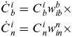 $$\eqalign{& \dot C\hskip1pt_b^i = C\hskip1pt_b^i w_{ib}^b \times \cr & \dot C\hskip1pt_n^i = C\hskip1pt_n^i w_{in}^n \times} $$
solutions to which are:
 $$C\hskip1pt_i^{bt} - C\hskip1pt_i^{bt - 1} = C\hskip1pt_i^{bt - 1} \cdot T \cdot w\hskip1pt_{ibt - 1}^b \times \Rightarrow C\hskip1pt_{bt - 1}^{bt} = I + T \cdot w\hskip1pt_{ibt - 1}^b \times \Rightarrow C\hskip1pt_{bt - m}^{bt} = C\hskip1pt_{bt - 1}^{bt} C\hskip1pt_{bt - m}^{bt - 1} $$
 $$C\hskip1pt_i^{nt} - C\hskip1pt_i^{nt - 1} = C\hskip1pt_i^{nt - 1} \cdot T \cdot w_{int - 1}^n \times \Rightarrow C\hskip1pt_{nt - 1}^{nt} = I + T \cdot w\hskip1pt_{int - 1}^n \times \Rightarrow C\hskip1pt_{nt - m}^{nt} = C\hskip1pt_{nt - 1}^{nt} C\hskip1pt_{nt - m}^{nt - 1} $$
The optimal approach in the references take the C b(0)n(0) as the initial attitude matrix, but here the C b(t−m)n(t−m) is the temporary initial attitude matrix. If the temporary initial attitude matrix C b(t−m)n(t−m), was known, the C bn(t) can be obtained by Equations (3), (4)and (5). So the method in this paper is called “a sliding optimization method for alignment based on inertial system”.
Then the most important value we have to obtain is the value of C b(t−m)n(t−m). Substituting Equation (3) into Equation (2) yields:
 $$\dot v^n = C\hskip1pt_{n(t - m)}^{n(\tau )} C\hskip1pt_{b(t - m)}^{n(t - m)} C\hskip1pt_{b(\tau )}^{b(t - m)} f^b - (2w_{ie}^n + w_{en}^n ) \times v^n + g^n, t - m \lt \tau \lt t$$
Multiplying C n(τ)n(t−m) on both sides,
 $$\hskip-6pt\eqalign{C\hskip1pt_{n(\tau )}^{n(t - m)} \dot v^n = & C\hskip1pt_{b(t - m)}^{n(t - m)} C\hskip1pt_{b(\tau )}^{b(t - m)} f^b - C\hskip1pt_{n(\tau )}^{n(t - m)} (2w_{ie}^n + w_{en}^n ) \times v^n + C\hskip1pt_{n(\tau )}^{n(t - m)} g^n \,,\,t - m \lt \tau \lt t} $$
Or equivalently,
 $$\eqalign{C\hskip1pt_{b(t - m)}^{n(t - m)} C\hskip1pt_{b(\tau )}^{b(t - m)} f^b & = C\hskip1pt_{n(\tau )}^{n(t - m)} \dot v^n + C\hskip1pt_{n(\tau )}^{n(t - m)} (2w_{ie}^n + w_{en}^n ) \times v^n - C\hskip1pt_{n(\tau )}^{n(t - m)} g^n, t - m \lt \tau \lt t} $$
Equation (9) forms the basis for the optimization approach, which could be readily applied to the alignment problem discussed in this paper if the velocity rate  $\dot v^n$ was provided.
Integrating Equation (8) on both sides over the time interval of interest:
 $$\eqalign{ \int_{t - m}^t {C\hskip1pt_{n(\tau )}^{n(t - m)} \dot v^n} d\tau = &C\hskip1pt_{b(t - m)}^{n(t - m)} \int_{t - m}^t {C\hskip1pt_{b(\tau )}^{b(t - m)} f^b d\tau -} \int_{t - m}^t {C\hskip1pt_{n(\tau )}^{n(t - m)} (2w_{ie}^n + w_{en}^n )} \cr & \times v^n dt - \int_{t - m}^t {C\hskip1pt_{n(\tau )}^{n(t - m)} g^n d\tau}, t - m \lt \tau \lt t} $$
For the whole integration process in Equation (10), τ is the variable, the integrating range of the definite integral is the data segment between t−m moment to t moment, t and m are not the variables, so we can take the navigation frame of t−m moment as a kind of i-frame, so
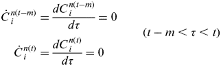 $$ \matrix{ {\dot C\hskip1pt_i^{n(t - m)} = \displaystyle{{dC\hskip1pt_i^{n(t - m)} } \over {d\tau }} = 0} \cr {\dot C\hskip1pt_i^{n(t)} = \displaystyle{{dC\hskip1pt_i^{n(t)} } \over {d\tau }} = 0} \cr } \quad\quad (t - m \lt \tau \lt t)$$
The left term of Equation (10) develops as
 $$\int_{t - m}^t {C\hskip1pt_{n(\tau )}^{n(t - m)} \dot v^n} d\tau = \int_{t - m}^t {\left( {C\hskip1pt_{n(\tau )}^{n(t - m)} v^n} \right){ \hskip-2pt\prime}} d\tau - \int_{t - m}^t {\dot C\hskip1pt_{n(\tau )}^{n(t - m)} v^n} d\tau $$
in which C n(τ)n(t−m) is the navigation frame of the moment τ with respect to the navigation frame of the moment t−m.
 $$\dot C\hskip1pt_{n(\tau )}^{n(t - m)} = \left( {C\hskip1pt_i^{n(t - m)} C\hskip1pt_{n(\tau )}^i} \right) { \hskip-2pt\prime} = \dot C\hskip1pt_i^{n(t - m)} C\hskip1pt_{n(\tau )}^i + C\hskip1pt_i^{n(t - m)} \dot C\hskip1pt_{n(\tau )}^i $$
Combining Equations (12) and (4):
 $$\dot C\hskip1pt_{n(\tau )}^{n(t - m)} = C\hskip1pt_i^{n(t - m)} \dot C\hskip1pt_{n(\tau )}^i = C\hskip1pt_i^{n(t - m)} C\hskip1pt_{n(\tau )}^i w_{in}^n \times = C\hskip1pt_{n(\tau )}^{n(t - m)} w_{in}^n \times $$
Rewrite Equation (11):
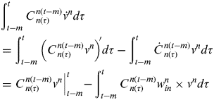 $$\eqalign{& \int_{t - m}^t {C\hskip1pt_{n(\tau )}^{n(t - m)} \dot v^n} d\tau \cr & = \int_{t - m}^t {\left( {C\hskip1pt_{n(\tau )}^{n(t - m)} v^n} \right){ \hskip-2pt\prime}} d\tau - \int_{t - m}^t {\dot C\hskip1pt_{n(\tau )}^{n(t - m)} v^n} d\tau \cr & = \left. {C\hskip1pt_{n(\tau )}^{n(t - m)} v^n} \right|_{t - m}^t - \int_{t - m}^t {C\hskip1pt_{n(\tau )}^{n(t - m)} w_{in}^n \times v^n} d\tau} $$
Substituting Equation (14) into Equation (10) and reorganizing the terms yields the velocity integration formula as
 $$C\hskip1pt_{b(t - m)}^{n(t - m)} \alpha _v = \beta _v $$
in which
 $$\eqalign{& \alpha _v \buildrel \Delta \over = \int_{t - m}^t {C\hskip1pt_{b(\tau )}^{b(t - m)} f^b d\tau} \cr & \beta _v \buildrel \Delta \over = \left. {(C\hskip1pt_{n(\tau )}^{n(t - m)} v^n )} \right|_{t - m}^t + \int_{t - m}^t {C\hskip1pt_{n(\tau )}^{n(t - m)} w_{ie}^n \times v^n} d\tau - \int_{t - m}^t {C\hskip1pt_{n(\tau )}^{n(t - m)} g^n d\tau}} $$
Note the four elements unit quaternion 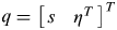 $q = \left[ {\matrix{ s & {\eta ^T} \cr}} \right]^T $, where s is the scalar part and η is the vector part, is used to encode the initial body attitude matrix C b(t−m)n(t−m), the relationship between these two rotation parameters is:
 $$C\hskip1pt_{b(t - m)}^{n(t - m)} {\rm =} \unknown (s^2 - \eta ^T \eta )I + 2\eta \eta ^T - 2s(\eta \times )$$
Define the quaternion multiplication matrices by
 $$\mathop {\left[ q \right]}\limits^ + \buildrel \Delta \over = \left[ {\matrix{ s & { - \eta ^T} \cr \eta & {sI + (\eta \times )} \cr}} \right], \quad \mathop {\left[ q \right]}\limits^ - \buildrel \Delta \over = \left[ {\matrix{ s & { - \eta ^T} \cr \eta & {sI - (\eta \times )} \cr}} \right]$$
Then Equation (15) is equivalent to  $( {\mathop {[ \hskip1pt{\beta (t_M )} ]}\limits ^ + - \mathop {[ {\alpha (t_M )} ]}\limits^ -} )q = 0$, and the determination of the attitude quaternion can be posed as a constrained optimization
 $$\mathop {\min} \limits_q q^T Kq , \quad {\rm subject \ to} \quad q^T \, q=1 $$
where the 4×4 real symmetric matrix
 $$K \buildrel \Delta \over = \sum\limits_M {( {\mathop {[ {\beta (t_M )} ]}\limits^ + - \mathop {[ {\alpha (t_M )} ]}\limits^ -} )^T ( {\mathop {[ {\beta (t_M )} ]}\limits^ + - \mathop {[ {\alpha (t_M )} ]}\limits^ -} )} $$
It can be proved that the optimal quaternion is exactly the normalized eigenvector of K belonging to the smallest eigenvalue.
Equation (15) is a fixed length integration function of the initial attitude matrix C b(t−m)n(t−m), with the two vectors α v and β v evidently defined in Equation (15). Note that α v and β v are respectively functions of the gyroscope/accelerometer outputs and the aided velocity/position information during the alignment period [0,t]. Theoretically, if there exist two linearly independent α v or β v, the initial attitude matrix C bn(t−m) for a fixed data segment can be uniquely determined, and further update the attitude matrix from the moment t−m to the moment t.
The value m is very important. Each time we get the C bn(t), the m length data segment from t−m to t must be used.
The optimal alignment is a method based on integrated form. The value m just represents the length of integral interval. If the value is big, the precision may deteriorate due to the integration of bias. If the value is small the precision may also be far from satisfied because the random noise requires quite a long data segment to obtain the required statistical characteristic.
3.2. Alignment algorithms implementation
The recursive algorithm is summarized below; note that the matrix K can be cursively computed using its previous value. Suppose T is the time interval indexed by k, the length of data for optimization is m, a constant value. The current time t=kT.
Initialization: set k = 0, Let C b(t−m)b(t) = C n(t−m)n(t) = I and K = 04×4
Step 1: set k=k+1
Step 2: Update C b(kT−m)b((k−1)T) to C b(kT−m)b(kT) using the gyroscope outputs w ibb, and C n(kT−m)n((k−1)T) to C n(kT−m)n(kT) using the w inn;
Step 3: Compute α(kT) and β(kT) using the accelerometer outputs fband the velocity measurements. (see Equation (16))
Step 4: Update K((k−1)T) to K(kT) with the resultant α(kT) and β(kT) according to Equations (16) and (18)
 $$K(kT) \approx \int_{kT - m}^{KT} {( {\mathop {[ {\hskip1.5pt\beta (t)} ]}\limits^ + \mathop { - [ {\alpha (t)} ]}\limits^ -} )^T ( {\mathop {[ {\beta (t)} ]}\limits^ + \mathop { - [ {\alpha (t)} ]}\limits^ -} )dt} ;$$
Step 5: Determine the initial attitude quaternion q by calculating the normalized eigenvector of K(kT) belonging to the smallest eigenvalue;
Step 6: Obtain the attitude matrix at current time using Equations (3) and (17);
Step 7: Go to Step 1 until the end.
4. TEST RESULTS
This section is devoted to numerically examining the fixed length optimal algorithms proposed in this paper.
4.1. The Simulation data
In this section, the validity of our algorithm and the influence of random and bias errors will be demonstrated. First, the conditions for the simulation are as follows: the true attitude is supposed to be (θ=−10°, γ=−20°, φ=−30°); the sampling frequency is 10 Hz; the longitude is 114·802° and latitude is 30·58°; the bias of the gyro is 0·01°/h, random noise is 0·01°/h; the bias of the accelerometer is 1×10⁻⁴ g, random noise is 1×10⁻⁵ g.
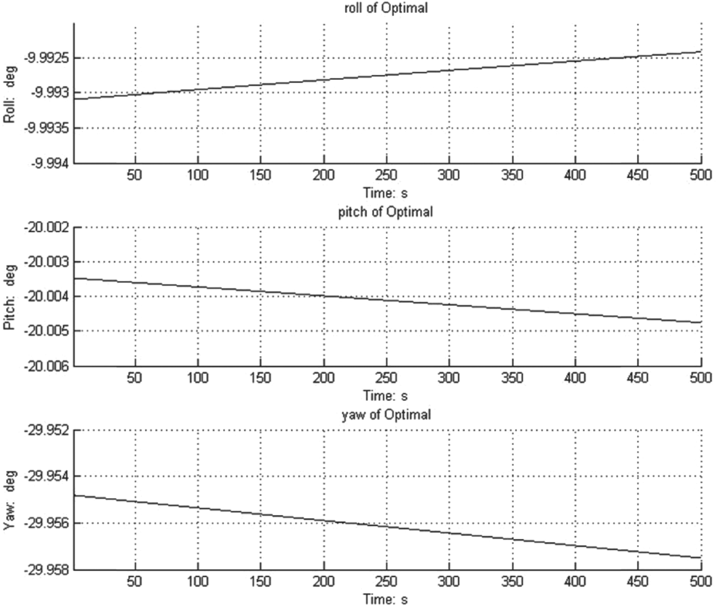
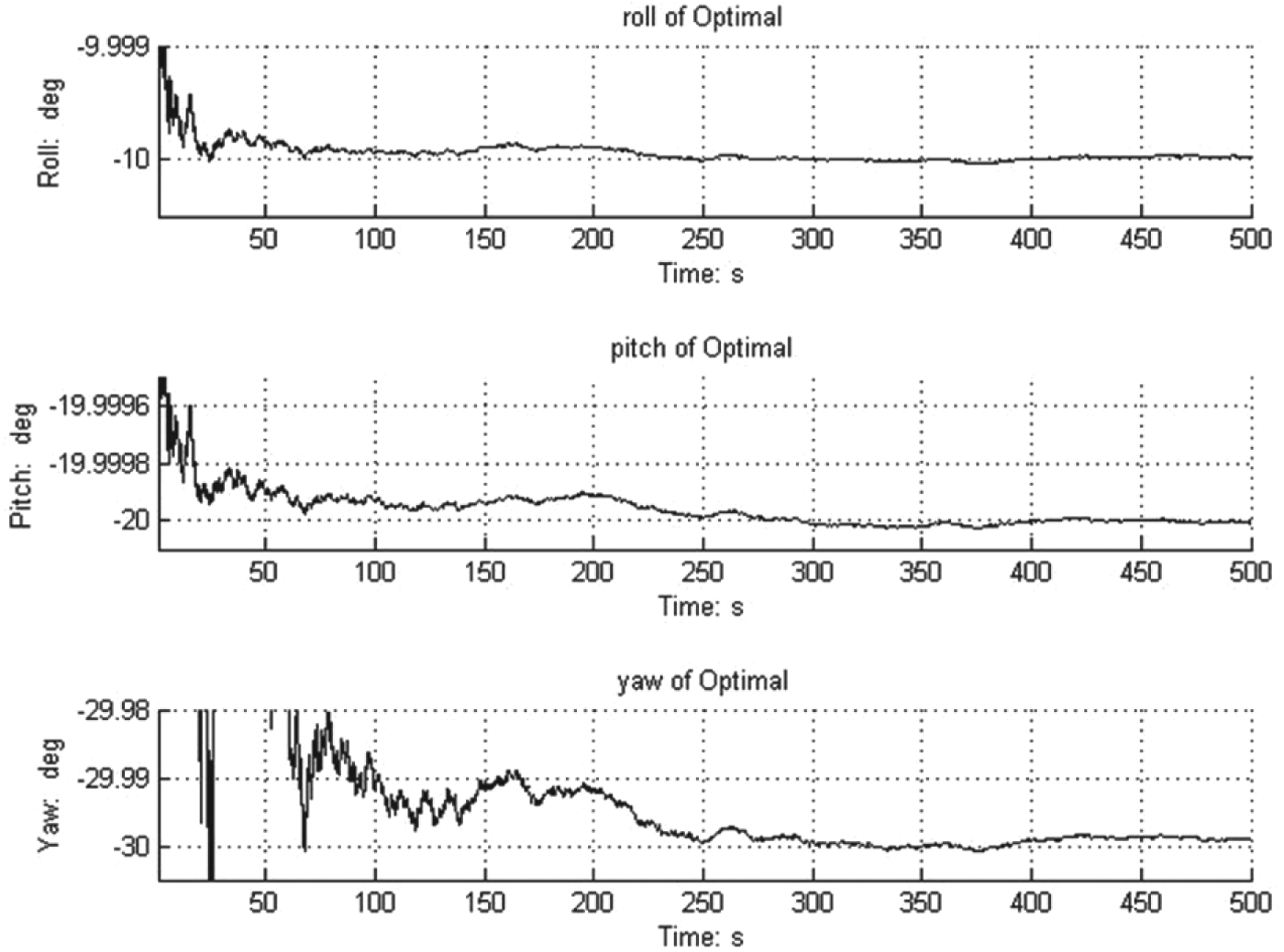
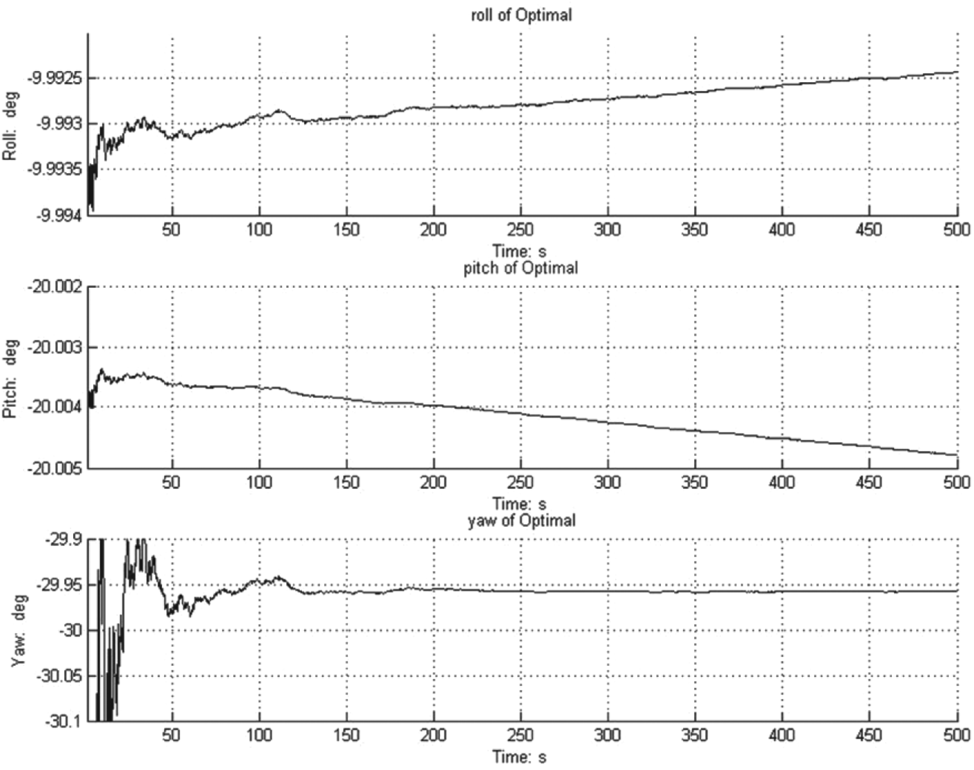
To illustrate the influence of the random noise and bias with the method in the reference clearly (Wu et al., Reference Wu, Wu, Hu and Hu2011), Figure 1 shows the alignment performance using the optimal alignment method under the circumstance that there is only bias in the simulation data. It can be seen that the bias makes a directional deviation to the alignment; the longer the data segment, the worse the deviation. Figure 2 shows the performance in the case of only random noise in the simulation data. It can be seen that random noise requires quite a long data segment to achieve alignment with almost no deviation. The alignment performance in the condition of the simulation data with both random noise and bias can be seen in Figure 3. This simulation data is regarded as the closest to true data. From Figures 1 to 3, we can conclude that the alignment requires a suitable length of data segment to restrain the influence of both random noise and bias.
Simulation data with only bias.

Simulation data with only random noise.
Simulation data with random noise and bias.
4.2. The Measured Data
In the second supporting part, a piece of test data segment of the Fibre Optical Gyroscope (FOG) SINS was collected. The FOG SINS was installed on a double-axis turntable, as shown in Figure 4.
IMU of FOG Strapdown INS.
IMU on turntable.
In order to evaluate the accuracy of alignment we needed a criterion for comparison. Thus we ensured that the turntable had a highly accurate level through a level meter and an exact heading through an optical theodolite. 2000 s of static data from the FOG SINS was collected on the double-axis turntable.
The parameters were as follows: attitude of IMU was (θ = 0°, γ=0°, φ=36·8°). The length of the data was 2000 s, the sampling frequency was 10 Hz and the longitude and latitude were 114·802° and 30·58° respectively.
Figures 5 to 7 provide the attitude estimated by the method proposed with the test segment. Figure 5 shows the roll angle, Figure 6 shows the pitch angle, and Figure 7 shows the yaw angle.
The optimal roll alignment.
The optimal pitch alignment.
The optimal yaw alignment.
Each figure has four curves, including the method in this paper when the value of m respectively is 10, 100, 1000, and the method proposed by the reference (Wu et al., Reference Wu, Wu, Hu and Hu2011). Through the figures we can see the curve of m=10 gives a high accuracy level, but a rather coarse heading. The curve of m=1000 shows a volatility in the level attitude. The curve of the method in the reference (Wu et al., Reference Wu, Wu, Hu and Hu2011) shows obvious flutter due to the integration over a long time from 0 to t. The curve of m=100 has a better performance.
5. CONCLUSIONS
A good attitude initialization is very important for rapid and accurate SINS fine alignment. A new decomposed form and a fixed integral interval sliding method for optimization-based alignment has been proposed in the paper. The style of decomposition is more reasonable and suitable than that in Wu et al. (Reference Wu, Wu, Hu and Hu2011) due to the noise in the outputs of the IMU. The length of the data segment is the key factor in determining current attitude. If the length is too long the precision deteriorates due to the integration of bias. If the length is too short the precision also deteriorates because of the random noise. The effectiveness of the method has been verified by simulated and measured data.
ACKNOWLEDGMENTS
This work is supported in part by the National Major Special Instrument of China (No. 2011YQ12004502), the National Natural Science Foundation of China (No. 61304241, 61104184) and the Pre-research fund of the General Armaments Department (No. 201300000008).