I. INTRODUCTION
The photoelectrochemical water splitting is an alternative technique developed to meet the global oil demand crisis back in 1972 by Fujishima and Honda with TiO2 n-type semiconductor. Reference Fujishima and Honda1 Metal oxide electrodes have been widely used in this technique due to broad ranges of interesting functionalities: ability to harvest visible solar photons, stability in neutral and basic environment, environmentally friendly, and abundance in the Earth's crust as mineral deposit. The photoelectrochemical properties of metal oxide semiconductor electrode are very significant from the perspectives of the efficiency of the electrode for solar fuel generation. We basically take two examples here: photoanodic current density and photocathodic current density. Here, the former originated due to the water oxidation reaction while the latter from water reduction reaction. In that respect, several reports are being made in the current mandate about the photoanodic current density and efficiencies of the various metal oxide photoelectrodes. But all of these electrodes reported in nanoparticulate form and structurally tunes into nanowire, nanorod, nanoflower etc. But the photoelectrochemical properties of this kind of electrode in hybrid form have not been explored widely. Hybrid here does not mean toward doped with cations and anionic counterparts. While it means a heterostructural form of electrode where two different metal oxides are considered. Considering this theme, in the present investigation, a simple hydrothermal method is developed to form a hybrid heterostructured electrode of ZnO and hematite in a specific architectural form and also to study its photoelectrochemical properties. Getting back to hematite, this is considered for photoelectrochemical water splitting due to its high alkali stability, visible light absorbing energy band gap, and wide abundance. Reference Sartoretti, Alexander, Solarska, Rutkowska and Augustynski2–Reference Zhong, Sun, Inumaru and Gamelin6 Due to its reported low efficiency for photo electrochemical (PEC) application in a nanoparticulate form, hematite based hierarchical nanoarchitectures of different morphologies (nanowires, nanobelts nanotubes, nanorods etc.) have been described. Reference An, Zhang, Pan and Yu7–Reference Cao, Liu, Gao, Sun, Wu, Hu and Wang13 These nanaoarchitectures are mostly made with hydrothermal reactions, chemical vapor depositions or ionic-liquid assisted routes. In the present investigation, the focus will be attained on a two-pot hydrothermal procedure using amino acid (L-arginine) and hexamine as a structure directing agent, followed by pre-sensitization of the hematite with ZnO to get globular microflower shaped architectures. In this type of hydrothermal chemistry, morphology is controlled by hydrothermal-condensation chemistry onto the substrate. Reference Vayssieres14 Hence, so far, various hematite based nanoarchitctures have been reported in the photoelectrochemical water splitting application. Succeeding, the application of ZnO as a photoelectrode will be brought into thoughtfulness. For the same, it has been ground out that ZnO is a suitable photoanode for water splitting reaction due to its electrochemical stability and high electron mobility. Reference Klingshirn15 In the present investigation, stability is not an issue as the focus is to understand the effect of hybrid nanoarchitectures. Application of ZnO to understand artificial photosynthesis process was an important research finding by Tributsch and Calvin, Reference Tributsch and Calvin16 where they sensitized the ZnO single crystal with chlorophyll molecule and found the electron injection properties of dye molecule on excitation with light. This basically generated the obtained photocurrent. ZnO is used for PEC applications in various structural forms such as nanowire, nanorods, nanoparticulate films etc. Reference Yang, Wolcott, Wang, Sobo, Fitzmorris, Qian, Zhang and Li17–Reference Wolcott, Smith, Kuykendall, Zhao and Zhang19 It has a band gap of 3.2 eV Reference Srikant and Clarkea20 which makes it less effective for the PEC application as it is sensitive to UV light only. Nevertheless, various schemes had been swept up to counter this disadvantage with electronic band gap tuning with doping, quantum dot sensitization, and surface functionalization. Reference Yan, Ahn, Shet, Deutsch, Huda, Wei, Turner and Al-Jassim21–Reference Wei, Ke, Kong, Liu, Jiao, Lu, Du and Sun29 In quantum dot sensitization, ZnO nanowire array was sensitized with CdTe quantum dots with the more favorable conduction band electron transfer into ZnO for effective water splitting action. Reference Chen, Chen, Chang, Tsai, Liu, Hu, Chang and Chen25 Density functional theory had also been applied to make optimized ZnO/ZnS heterostructure with improved optical properties. Reference Schrier, Demchenko and Wang30 But it has also one good property in terms of its conduction band situated over the water reduction potential and therefore needs less apply bias in contrary to hematite. Reference Grätzel31 ZnO thin films have been made with other schemes such as spray pyrolysis, hydrothermal methods, atomic layer deposition, and solution deposition. Reference Wolcott, Smith, Kuykendall, Zhao and Zhang19,Reference Yan, Ahn, Shet, Deutsch, Huda, Wei, Turner and Al-Jassim21,Reference Wei, Ke, Kong, Liu, Jiao, Lu, Du and Sun29,Reference Bora and Braun32 Al doped ZnO thin films made by atomic layer deposition (ALD) are used as an alternative substrate for organic photovoltaic devices. Reference Saarenpää, Niemi, Tukiainen, Lemmetyinen and Tkachenko33 ZnO/hematite based heterostructured system was formed by aqueous hydrolysis of FeCl3 and its photocatalytic properties had been investigated in past studies. Reference Achouri, Corbel, Aboulaich, Balan, Ghrabi, Said and Schneider34 Nanostructured ZnO based photoelectrochemical solar cell had been fabricated with 5% efficiency following dye-sensitization approach. Reference Keis, Magnusson, Lindström, Lindquist and Hagfeldt26 Also, ZnO architectures had been manufactured by wet etching and chemical precipitation method where its photocatalytic water splitting functionality was validated. Reference Janet, Navaladian, Viswanathan, Varadarajan and Viswanath35 ZnO nanorod had been fabricated using the low cost hydrothermal technique with premodified indium doped tin oxide (ITO) substrates with ZnO nanoparticles and the effect of hydrothermal growth time and temperature were optimized in a different study. Reference Guo, Diao and Cai36,Reference Guo, Diao, Wang and Cai37 In this case, the orientation of ZnO nanorod on the substrate allows better control of photogenerated electron path and charge separation with improved photoelectrochemical properties.
Due to both its positive and negative properties for PEC application, the idea now is to improve the PEC application in combination with hematite. For the same, two-pot hydrothermal experiment has been planned to make hybrid nanostructures where combined functionalities of both ZnO and hematite can be involved into account. Accompanied by this, detailed photoelectrochemical properties of the ZnO/hematite will be brought into thoughtfulness.
II. METHODS AND MATERIALS
A. Synthesis
All chemicals used during the present investigation were obtained from Sigma Aldrich (Buchs, Switzerland) with 99% purity. For the synthesis of Si doped hematite, already published procedure followed for the synthesis of precursor Reference Bora38 and consequent dip coating of hematite film. Here, silicon doped hematite film was obtained by repeated dip coating and heat treatment of optimized silicon containing iron oleate precursor (0.5%) with tetra ethyl ortho silicate (TEOS) as an interfacial layer on a fluorine doped tin oxide substrate. Note that fluorine doped tin oxide (FTO) is coated onto a glass substrate. The doping level of silicon into hematite lattice is 0.5% Si and intrinsic carrier doping type is n-type. Here, FTO makes an ohmic contact to the hematite with boosting of electron transport through its bulk to the counter electrode. Please note that during the water oxidation reaction, electron and hole pairs are generated separates from each other with a definite applied bias.
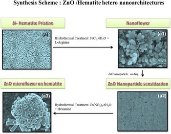
The process takes up with the dip coating of 1 layer of precursor on fluorine doped tin oxide substrate with postdrying and heat treatment procedure at 500 °C for 30 min. This results in a 180 nm thick film, which is further given multilayer treatment following the same approach except with an isothermal heating at 500–760 °C for 60 min. During the high temperature treatment, fluorine can diffuse to the hematite lattice. However, from the X-ray photoelectron spectroscopy (XPS) survey scan, no doping of fluorine ion into the hematite lattice has been observed during high temperature annealing. The survey spectrum of silicon doped hematite is shown in Fig. S1 in the supporting section. The final film showed a thickness of around 600 nm and exhibited maximum current density. For clarity, this film is designated here as “A”. Subsequently, the film A was given hydrothermal treatment with the already published procedure as described elsewhere. Reference Bora, Braun, Erni, Fortunato, Graule and Constable39 Here film A was given hydrothermal treatment with FeCl3 6H2O and L-arginine (5: 5 mmol) at 95 °C for 48 h. The obtained film in this case is A1. Next, film A1 was sensitized by the drop casting of ZnO nanoparticle suspension (200 mg sonicated in ethanol) and this is designated as film A2. Nanoparticle is obtained from the annealing of Zn-oleate precursor use for making a nanostructured ZnO thin film. Reference Wei, Ke, Kong, Liu, Jiao, Lu, Du and Sun29 The idea of sensitization with nanoparticle is to use it as a seeding center for growing hybrid nanoarchitectures. A similar strategy had been used for making NiO/hematite heterostructure photoelectrode. Reference Bora, Braun, Steifel, Erni, Müller, Döbli and Constable40 Finally, the film A2 was given hydrothermal treatment with similar 1:1 mmole ratio of Zn(NO3)3 6H2O and hexamine as capping agent at 95 °C for 21 h. This results into film A3 which is here seen as hierarchical ZnO/hematite hetero nanoarchitectures.
B. Characterization
The optical properties of all films have been measured by UV-Vis spectrophotometer (Carry Scan 50, Varian, Amstelveen, The Netherlands). For calculating the energy band gap, Tauc methodology for direct and indirect band gap transitions was used. The structural properties of all films were tested with powder x-ray diffractometer (Pan Analytical Xpert Pro, PANalytical GmbH, Kassel, Germany) with Cu Kα radiation. For validating the morphology of the electrode HITACHI S-4800 field emission scanning electron microscope (Hitachi Corp., Krefeld, Germany) was used embedded with an energy dispersive X-ray (EDX) spectrometer from Bruker Corporation (Karlsruhe, Germany). The transmission electron microscope used in the present investigation is JEOL JEM 2200FS operating at 200 keV (JEOL Europe, Nieu-Vennep, The Netherlands). The photoelectrochemical properties have been studied with a photoelectrochemical work station [with a Voltalab 80 potentiostat (Radiometer Analytical, Villeurbanne, France) equipped with three electrode cappuccino cell, Ag/AgCl reference electrode (3 M KCl; supplier-Radiometer analytical) and Pt plate as a counter electrode (area 1 cm2). The scan method was: linear sweep voltammetry with a scan rate of 30 mV/s. The electrolyte used was 1 M KOH with 13.50 pH. The photocurrent density was measured by illuminating the samples with AM 1.5 solar simulated sunlight from Xe light source (from LOT Oriel, Quantum Design GmbH, Darmstadt, Germany) through a 0.5 cm2 orifice. The electrode with 2.6 cm2 geometrical area was immersed in 1 M KOH.
III. RESULTS AND DISCUSSION
The synthesis of ZnO/hematite heterojunction photoelectrode was performed with the aid of two-reactor hydrothermal modifications as discussed elsewhere (Scheme 1). Reference Bora, Braun, Steifel, Erni, Müller, Döbli and Constable40
Two-step hydrothermal functionalization of silicon doped hematite film into a hierarchical ZnO/hematite hetero nano architecture.

Here, hydrothermal treatment of the silicon doped hematite film was first carried out accompanied by the sensitization of electrode with ZnO nanoparticle of size around 20–30 nm. The as-obtained ZnO treated film was given a final hydrothermal treatment in the presence of zinc salt and hexamine. Here, hexamine works as a structure directing agent. Reference Samanta, Patra and Chaudhuri41 The synthesis procedure is rather simple for getting such kind of heterojunction photoelectrode. The chemistry involved does not consider in particular. However, in the conversion of silicon doped hematite film to flower shaped morphology, the heterogeneous nucleation mechanism takes place. Reference Nakamura and Kurokawa42 Well, in case of ZnO treatment, a nucleation induced growth phenomena have been observed with the formation of ZnO nanorod. Here, ZnO nanorod assembles into a flower shaped 3D structure. The globular flower is believed to take part in the light harvesting mechanism of the electrode while it is not the case. The presence of Zn ion in hematite lattice makes it to show p-type behavior as exemplified by high-rise in cathodic photocurrent density. The structure obtained is stable in the preliminary investigation, but decomposed afterward the photoelectrochemical operation. It is believed that proper tuning of electrolyte concentration definitely plays a role in this case.
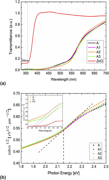
Thus far, the associated chemical phenomena have been leveled out. To understand the physical properties of heterojunction photoanode, UV–Vis spectroscopy was used to understand the optical properties, which are a cornerstone experiment in the photoelectrochemistry field. For the same, the UV–Vis spectrum [Fig. 1(a)] was carried out on all the films (from A to A3) to consider any alteration in the band gap of hematite. From the transmittance spectrum, it is evident that all films absorb at usual hematite absorption band (550 nm) while the absorption increases from films A1 to A3 near to the UV wave length. Here, ZnO present on the hematite surface absorbs at around 358 nm, which also contributes to the usual hematite UV absorption band. Followed by this, the band gap of all films has also been calculated by employing Tauc model for indirect band gap transition [Fig. 1(b)]. Here it is found that the band gap of hematite remains stable (2.15 eV) even after rigorous functionalization with ZnO counterparts in the presence of organic medium such as hexamine. While the band gap of ZnO functionalized films (A2 and A3) are also calculated [as shown in the inset of Fig. 1(b)] by employing Tauc model for direct band gap transition. The usual band gap of ZnO is around 3.2 eV while in this case, after functionalization and in combination with hematite band gap slightly changes to 3 eV (A3) and 2.9 eV (A2). While these changes are not so trivial, it is concluded that in the heterojunction photoanode, both hematite and ZnO band gap remain intact. This assists in the absorption of photons in right wave length and the charge transfer process from the their conduction band to electrolyte and hole transfer to hematite valance band.
(a) UV–Vis transmittance spectrum of films A to A3; (b) energy band gap of all films, calculated using Tauc model for indirect band gap transition [insert: energy band gap of ZnO containing films A2 and A3 along with standard ZnO film calculated using direct band gap transition].

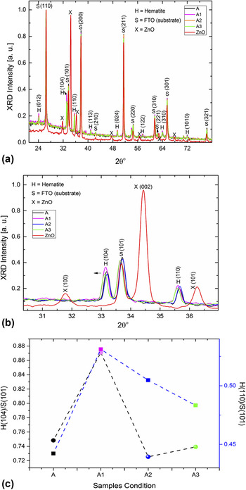
Adopted by the optical properties, the structural properties of hematite and ZnO have also been studied to see any crystallographic changes in the hematite lattice and vice versa. On comparing the x-ray diffractograms of four different films [Fig. 2(a)], it is evident that hematite Bragg diffraction peak intensities overshadow that of ZnO in case of all films with the visual aspect of peak intensities from (012), (104), (110), (113), (024), (122), (310), and (1010) planes as well as (110), (101), (200), (210), (211), (220), (310), (221), (301), and (321) crystal planes from the substrate (FTO), respectively. Note that only films A2 and A3 in this case gets ZnO functionalization. A2 films were sensitized with ZnO nanoparticles prior to hydrothermal treatment with zinc salts and hexamine as in A4. A standard x-ray diffractogram of ZnO films has also been compared to these films for the observational point of view. But here, no ZnO Bragg diffraction peak can be determined, which allows sticking only to hematite crystallographic structure changes. Hence now the idea is to see a profound change in hematite crystal lattice. Followed by this, the x-ray Bragg diffraction peaks of hematite (104) and (110) have been expanded between the positions 31 and 36° [Fig. 2(b)]. From here, it is observed that the (104) peak position remains intact for the films A and A3 while for the respective hydrothermal treatment with iron and zinc salts, the position slightly changes in the lower Bragg diffraction angle and it also runs in case of (110) as well. The reason behind is that during hydrothermal treatment, a more amorphous form is deposited on original hematite films (A). Note that all peak intensities in this case are normalized to that of the peak maximum from the substrate. The substrate in this case is fluorine doped tin oxide. The intensities for all the cases are same and substrate intensities remain constant indicating the fact that there are no thickness induced changes in the crystallographic structure. Based upon this fact, the relative Bragg peak intensity ratio between hematite (104) & (110) and substrate (101) has been compared to see any crystallographically preferred growth due to rigorous hydrothermal treatment. From the comparison as shown in Fig. 2(c), it is observed that only in case of film A1, there are changes in the Bragg peak intensity ratio for both (110) and (104) peaks while for other films it seems to be not changed significantly. This is already grounded from an earlier work where posthydrothermal treatment of hematite with amino acid leads to crystallographically preferred growth of nanoflower like architectures. Reference Bora, Braun, Erni, Fortunato, Graule and Constable39 Note that the hematite (110) planes with respect to (001) basal plane conduct more electrons. Reference Warschkow, Ellis, Hwang, Mansourian-Hadavi and Mason43 The (110)/(101) peak ratio bit changes with respect to (104)/(101) peak ratio for films A2 and A3. But after post functionalization, the ratio almost remains same with that of film A2. Well, it is not the case in case of (104)/(101) peak ratio for films A2 and A3. There is a sudden drop in the (104) peak ratio on putting ZnO counterpart on hematite. Hence, it can be conclusive evidence that the hematite crystal structure changes after functionalization with ZnO due to some doping induced effect where zinc ions diffuse into the hematite lattice structure during hydrothermal treatment. Nevertheless, there is no direct evidence to confirm this. It will be a study for the next step. This result can be envisioned from the obtained photocurrent density measurement where a low magnitude of photoanodic current density has been kept pointing toward p-type behavior. Lastly, as mentioned in the synthesis section, such type of fluorine doping was recently validated in the work of tantalum doped hematite. Reference Zhang, Li, Wang, Fan and Bard44 The formation of TaO2F phase in the X-ray diffraction (XRD) confirmed the fluorine doping for high temperature annealed samples. But if we carefully look into the XRD of silicon doped hematite film, we cannot see the formation of such phases. Also, in another study reported by Yang et al., for TiO2 single crystals, Reference Yang, Sun, Qiao, Zou, Liu, Smith, Cheng and Lu45 it was postulated that with fluorine doping (110) plane normally takes a preferential orientation with high electronic conductivity across (001) basal plane. But when we look into the XRD pattern (Fig. S2), the (110) plane actually shrinks, which is actually opposite to the case of fluorine doped TiO2. In this case, fluorine forms a strong bond with Ti, leaving (001) basal plane thermodynamically more stable.
(a) X-ray diffractogram of all films A–A3; (b) expanded view of the (110) and (104) Bragg diffraction planes from hematite; (c) comparison of Bragg diffraction peak intensities between hematite and substrate for all films to confirm any crystallographically preferred growth.

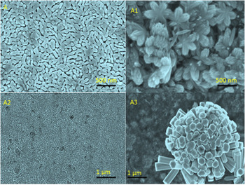
One interesting aspect of the present investigation is to obtain hierarchical nanoarchitectures of ZnO on hematite with a cheaper hydrothermal chemistry. To achieve the same, morphology of the film A–A3 was carefully investigated by using field emission scanning electron microscopy (FESEM). The FESEM images of films A–A3 have been indicated in Fig. 3.
FESEM imaging of films A–A3. Here, films A3 show a unique globular ZnO flower with assembly of individual ZnO nanorod.

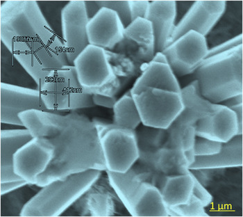
From here, it is apparent that the pristine slicon-doped hematite films show their usual dumbbell shaped morphology as-obtained in the earlier example. While hydrothermal treatment of Si doped pristine hematite film leads to hexapodial flower shaped morphology as shown in Fig. 3: A1. The sensitization of as-obtained hydrothermally processed film with ZnO nanoparticle does not show any remarkable morphology. The hydrothermal treatment of ZnO sensitized film with zinc salts and hexamine leads to an exciting morphology of globular ZnO microflower constituting ZnO nanorod assembly and it sits on leaves like hematite background (Fig. 3: A3). The high resolution imaging of each individual nanorod unit shows a size of ∼600 nm for each face (Fig. 4).
High resolution imagery of a specific nanorod to confirm its size.

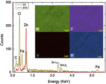
Followed by the morphological study with FESEM, the composition of the electrode is studied with Energy dispersive spectroscopy at Fe, O, and Zn electronic excitation edges. The elemental distribution of Fe, O, and Zn in the film A3 can be visualized from EDX mapping (inset of Fig. 5), where the EDX spectrum (Fig. 5) clearly demonstrated the presence Fe, Zn, and O elements at their respective energy positions. The presence of tin element at around 3.4 and 3.6 KeV signifies the presence of its two atomic absorption edges Lα1 and Lβ1. Besides these, the EDX spectrum of film A3 has also been compared to that of ZnO film deposited by solution deposition manner. Reference Achouri, Corbel, Aboulaich, Balan, Ghrabi, Said and Schneider34 In this particular case, it is noticed that the concentration of zinc element in the film A3 is lower than that of pure ZnO film and similar observation has been made for oxygen element concentration, which is actually getting higher after hydrothermal treatment. So from here, it is conclusive evidence that the hydrothermal treatment increases the oxygen content of the electrode followed by significant amount carbon element presences. Note that, the amount of oxygen in the pristine film A is also taken into account. Since the hydrothermal treatment experiment has been made in the ambient atmosphere, it is believed that the concentration of oxygen increases slightly. The presence of iron is also confirmed from the EDX spectrum, which confirms that due to rigorous hydrothermal treatment iron film hematite film remains intact.
EDX spectrum of film A3 shows the strong presence of Zn element. The inset shows the respective elemental distribution after hydrothermal treatment.

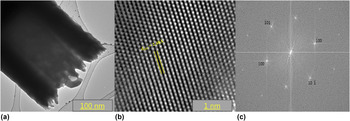
To examine the crystal structure of each individual nanorod, high resolution transmission electron microscopy (TEM) has been applied. Figure 6(a) shows the low resolution TEM image of a special section of ZnO nanorod. The picture presents a core shell pattern of the rod where a hollow clear portion has been followed. Next, high resolution mode was used to project a very minute percentage of the ZnO nanorod to look into the crystallographic arrangement [Fig. 6(b)]. From the high resolution TEM (HRTEM) image at 2 nm resolution, nice hexagonal pattern of ZnO crystallographic structure has been observed and the corresponding d-spacing value of 2.487 Å resembles that of (101) miller indices. This bears out well with the corresponding Bragg diffraction planes (101) from the XRD pattern of pristine ZnO film. Thus, in this instance, it can be reasoned that the hydrothermal treatment of ZnO nanoparticle evolves into ZnO nanorod on hematite with right structural conformity. To confirm more about the hexagonal pattern, the HRTEM image was fast Fourier transformed (FFT) with image J software [Fig. 6(c)]. The FFT image shows the selected area electron diffraction spots with the corresponding Miller indices from hexagonal ZnO nanorod. Reference Thankappan, Hari, Mathew, Ani Joseph, Erni, Bora, Braun and Nampoori46 The pattern further signifies the single crystalline nature of the nanorod.
(a) TEM imaging of individual ZnO nanorod. (b) Represents the HRTEM lattice imaging with corresponding d-spacing value for (101) Miller indices. (c) FFT image of ZnO nanorod showing the selected area electron diffraction spot with single crystalline character.

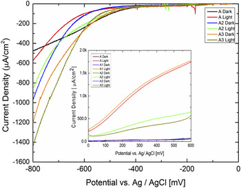
Finally, to check the functionality of the film A3, photoelectrochemical investigation has been performed with AM 1.5 solar simulated light in three electro-spectro-electrochemical cells using Ag/AgCl as reference and Pt as counter electrodes. The electrolyte used in this case is 1 M KOH to comply with hematite photoelectrochemical protocol. The pH of the respective electrolyte is 13.85. First all films have been given an anodic sweep from the respective open circuit potential (OCP) to 600 mV versus Ag/AgCl both under dark and light conditions (Fig. 7 inset).
Photocathodic properties of films A2 and A3 measured in a photoelectrochemical cell. The inset shows the photoanodic current densities of films A to A3.

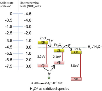
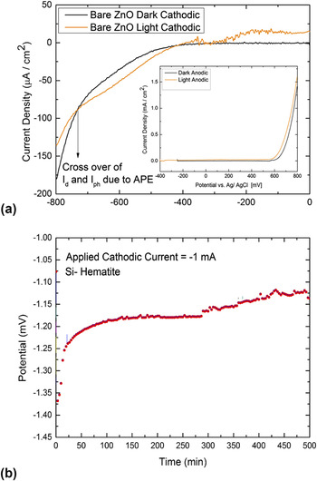
The film A shows its desired photocurrent density for silicon doped hematite 1.80 mA/cm2. Reference Bora38 The hydrothermal treatment of the film A with amino acid results into stellate shaped nanoflower, and the photocurrent gets higher as expected from an earlier investigation. Reference Bora, Braun, Erni, Fortunato, Graule and Constable39 In this case, the photocurrent density is slightly higher than that of pristine silicon doped hematite film. The dark current in all the cases remains flat, indicating no faradaic dark oxidative reaction. Apart from this, an interesting observation has been made for film A2 and A3. The photocurrent density for both A2 and A3 films drastically got lower with a half of the original photocurrent value (0.5 mA/cm2) from silicon doped hematite and hydrothermally treated one. The cause of this decrease will be explained next from the energy band diagram as described in Fig. 8. Before going to the preceding discussion, the photocathodic behavior of all films has been checked except for A2 by measuring the cathode current density. Here mostly focus is on A2 and A3 films. From the photocathodic current density measurement (Fig. 7), it is found that the film A3 shows a maximum current density of 1.4 mA/cm2. Here, it is noted that the photocurrent plateau disappeared and closely matched for all films at around 500 mV while the saturated current density was getting higher. Shift of photocurrent relative to the dark current appears due to the anomalous photo effects. Reference Rajeswar, Bard, Stratmann and Licht47 This in other words represents the crossover of both dark and light currents as explained in Fig. 7(b). For TiO2–NaOH electrolyte interface, Reference Morisaki, Hariya and Yazawa48 a similar type of anomalous photo effect (APE) induced by sub-band gap irradiation of the photoanode was observed in the saturation region of cathodic current flow. The origin of this photo effect was explained by the surface state mediated transfer of electrons from the semiconductor to the O2 of electrolyte. The surface state was triggered by the excitation of the definite wave length of incident light. This is imputable to the reversibility of semiconductor behavior of hematite from n-type to p-type with the fabrication of ZnO nanorod. That means that ZnO functionalization makes the original silicon doped hematite to exhibit more p-type behavior. The presented IV curve (Fig. 7) does represent typical photocurrent–potential behavior for a p-type semiconductor as evidenced from Ref. Reference Khan and Om Bockris49. If it's to be a photoresistor, the photocurrent should pass though the origin in a straight line form, but in this case, photocurrent follows the usual plateau shaped exponential. The shape also matched well to that of p-type GaP in 1 M NaOH. Reference Uosaki and Kita50 In the potential range from 0 to −600 mV, the exponential rise in photocurrent density is due to the decreased concentration of induced surface states and rate is controlled by the photo-excited carrier transport in semiconductor. The photoelectrochemical properties of cathodically polarized surfaces can be subdivided into two categories viz. bulk and surface processes. Reference Uosaki and Kita50 Bulk processes involve the photon absorption and excitation of photoelectrons to the semiconductor conduction band with the generation of electron–hole pairs. Photo-excited electrons transfer to the semiconductor surface with the de-activation of photogenerated electrons to the valence band. The surface processes involve the electron transfer to an oxidized species. If we consider this latter case, in the current ZnO/hematite system, the photogenerated hole on hematite surface oxidized the water molecule according to the following revised energy band diagram (Fig. 8) and photoelectron generated in the ZnO semiconductor surface transferred to an oxidant species, which is actually oxidized water molecule in the form of H3O+ ion forming hydrogen via a multistep mechanism as described elsewhere. Reference Uosaki and Kita50
Energy band diagram of ZnO/hematite hetero nanoarchitectures under photoelectrochemical condition.

The energy band alignment does play a role here. It has already been postulated for a ZnO, CdSe, and CdTe heterojunction system, where the photocurrent generated is strongly influenced by the energy band alignment, enabling the efficient injection of photogenerated electrons from ZnO to CdSe. Reference Wang, Wang, Wang, Liu, Wang, Wang, Xu, Zhang and Duan51 Now if this concept is extended to the present system, it is evident that due to the energy band alignment of the semiconductor with standard hydrogen electrode scale, electron transfer should be taking place from the conduction band of ZnO to the electrolyte and then from electrolyte to hematite with finally transfering to the SnO2 giving a photocathodic current. Please note that the photogenerated hole generated as mentioned above transferred from ZnO to hematite surface leading to the accumulation of the same and make the surface p-type. The excess holes further oxidized the water molecule and photoelectron generated on ZnO transferred to the oxidized water molecule finally producing hydrogen. All these steps take place during reverse scan or cathodically biased surface. The excess hole generated can oxidize ZnO and thereby the system is less stable under anodic condition. Overall the electrode should show cathodic current as shown in Fig. 7.
It is also agreed upon the fact that ZnO is not stable in 1 M KOH. The cathodic and anodic behaviors are as shown in Fig. 9(a). It resembles the photocurrent pattern of ZnO/hematite. The anodic current density decreases pointing to degradation of ZnO. The current generated is from the FTO substrate. In the cathodic scan, ZnO survives in 1 M KOH followed by the stability measurement of hematite with the application of cathodic current density [Fig. 9(b)]. The built in bias increases from −1.40 V to −1.10 V for 10 h measurement under chronopotentiometric condition.
(a) Photocathodic and photoanodic behavior of pristine ZnO film; (b) stability of hematite under cathodic chronopotentiometric condition.

IV. CONCLUSION
A simple hydrothermal functionalization method is reported to create mixed metal oxide hetero nanoarchitectures. The optical properties of the electrode show increased absorption of UV photons by the ZnO microflower counterpart while the band gap remains constant. The x-ray diffraction further confirms that after zinc hydrothermal functionalization of hematite, its (104) Bragg diffraction peak intensity ratio changes abruptly, pointing to structural changes by the diffusion of zinc ions into a hematite crystal lattice. However, it could not be proved in the current form of the manuscript. The morphology study indicates the formation of globular shaped ZnO microflower with a constellation of ZnO nanorods and the presence of Zn, Fe, and O elements is being confirmed by EDX spectroscopy. The HRTEM imaging shows the presence of right d-spacing to match with (101) miller indices and it's also in conformity with the XRD pattern of heterostructure film. Ultimately, the photocathodic properties of the electrodes are verified with −1.4 mA/cm2 current density and it is preferable to the right mismatch between the energy bands of hematite and ZnO. The present system is not sufficiently competitive, but an easy and convenient process is described during the current investigation. As a future outlook, the present electrode could also be applied to photoelectrochemical carbon dioxide reduction application.
Supplementary Material
To view supplementary material for this article, please visit http://dx.doi.org/10.1557/jmr.2016.107.
ACKNOWLEDGMENTS
Funding for this research was provided by the Swiss Federal Office of Energy Project No. 100411, the Seventh Framework Program “Novel Materials for Energy Applications” Grant No. 227179 (Nanotech–Nanostructured Photo-electrodes for Energy Conversion), and the Swiss National Science Foundation R'Equip No. 206021-121306. The author would like to thank Prof. Edwin C. Constable (University of Basel), Dr. Artur Braun and Prof. Thomas Graule (both Empa) for their kind support and encouragement. The writer would also wish to acknowledge the help from Dr. Rolf Erni from the electron microscopy center, EMPA Dübendorf for HRTEM measurement and Hansjurgen Schlinder from laboratory for high performance ceramics, EMPA Dübendorf for XRD measurement. The Spectro-electrochemical cell or cappuccino cell was made by Peter Wyss and Marc Zollinger (Empa Machine Shop) after a blueprint supplied by the Laboratory for Photonics and Interfaces, EPFL Lausanne.