1. INTRODUCTION
The essence of engineering design is the making of decisions. The designer makes decisions so that the design goals are best achieved without violating design constraints. The design process starts with the specifications, leading to the generation of design alternatives and then the selection of the best configuration among these. Finally, rigorous analytical methods are used to refine the selected configuration to fit the requirements.
This process involves conceptual design decisions and parametric design decisions. Consider, for example, the design of a linear motor to replace a hydraulic actuator. There are a number of potential design alternatives including linear synchronous motors (LSMs) and linear induction motors. Each of these types can be designed in numerous configurations, for example, moving magnets, wound field, and so forth. The goal of the conceptual stage of the design is to identify the most suitable configuration. Once a particular configuration is chosen it is refined in the detailed design stage.
In the parametric design stage the decisions need not be subjective. Design problems can often be expressed in the form of mathematical equations representing the details of the chosen configuration. The goal is to find optimal values of the variables while satisfying the constraints. A number of structured, step-by-step approaches have been developed to help the designer make decisions and achieve the final refined design. Many mathematical optimization algorithms are available to solve problems of this kind.
The application of computational decision-making techniques during the conceptual design stage is, at best, difficult mainly because the nature of conceptual design makes it largely unstructured. Often it is impossible to write common constraints that define the limits on the different configurations because different physical laws may govern different configurations. For example, in the linear motor design problem, one cannot write a single equation showing the saturation limit for a LSM as well as for a linear induction motor because the mode of magnetic field generation is different in the two types of motors.
Configuration selection is challenging. Traditional analysis and optimization would be applicable if the development of many configurations could proceed in parallel. However, the implications of such an approach on the direct development cost and time are clearly significant. Alternatively, many decisions are made using subjective evaluations that rely on a designer's previous experience and intuition. Intuition and experience are important and useful in the decision making process, but are not fool proof and may lead to inferior solutions. One would like to supplement these subjective evaluations with structured computational tools so that even an inexperienced designer can make correct decisions about design alternatives.
Even when mathematical techniques can be applied to directly find an optimal solution for a specific configuration the designer might want additional information. For example, the designers may want some understanding of the fundamental nature and limitations of various solution fragments, thereby enabling them to opportunistically create new designs. The importance of insight into critical interactions among features, redundant requirements, and inconsistencies cannot be ignored. If one configuration is found suitable for a design requirement then it is also important to know under which conditions it is suitable and what happens if the conditions are changed.
1.1. Constraint reasoning
Knowledge about how various constraints bind the objective, in which sense, and so forth, and reasoning based on this knowledge can be useful during configuration selection and refinement. Such reasoning with constraints is commonly used in the detailed design stage. Monotonicity analysis (Wilde, 1975; Papalambros & Wilde, 1979, 1988), constraint propagation (Davis, 1987; Sarma & Rinderle, 1992), Galileo constraint programming language (Bowen & Bahler, 1992; O'Sullivan, 2002), and also methods presented in Bordeaux et al. (2003) and Bowen (2003) are some examples of the existing constraint reasoning techniques. In this paper we present constraint reasoning-based methods for the conceptual design stage that provide critical insight and lead to design improvements. Figure 1 shows the proposed design flow chart that includes constraint reasoning and design improvement stages as part of the conceptual design. Linear motor design steps are also shown in the figure. We discuss one specific technique for constraint-aided design called constraint dominance, and demonstrate strategies for its employment with a design problem.

A flow chart depicting the proposed design steps. We suggest carrying out constraint reasoning based analysis in the conceptual stage of the design. Design steps for the example design problem, namely, the linear synchronous motor design problem, are also presented. [A color version of this figure can be viewed online at www.journals.cambridge.org]
1.2. Constraint dominance
Although all constraints are important in the design, under certain situations the satisfaction of one constraint may ensure the satisfaction of another constraint. Such a constraint is said to dominate the other. Proving dominance of one constraint over another is a useful constraint reasoning technique, especially at the conceptual stage of the design. If a constraint is proven to be dominated globally, that is, for the entire range of the design variable, then it can be ignored or deleted from the problem without altering the solution. Such a deletion can focus the designer's attention on the most influential constraints in the design and can lead to better design decisions. For example, in the case of the linear motor design problem, imagine that the designer has to choose either an induction motor or a synchronous motor configuration. If he knows that the satisfaction of the heat constraint ensures the satisfaction of other constraints, for both types of motors, then he can select the configuration solely by comparing the amount of heat generated by these two types of motors.
Determining if a constraint dominates another can be helpful in the parametric stage of the design also. If the designer can delete a highly nonlinear, nonconvex constraint using dominance, the problem representation may become simpler and more effective optimization algorithms may be applied.
1.3. Approach and scope
A number of computer tools exist to assist designers in the detailed design stage but the conceptual design stage is largely manual and unassisted. Although the emphasis on human experience and intuition in the conceptual design stage is justified, there is scope for automation of some steps in conceptual design. Previously researchers have developed computer tools to automate parts of the conceptual design stage. For example, O'Sullivan (2002) has extended the constraint programming language for the conceptual design stage, and Watton and Rinderle (1991a, 1991b) have presented strategies to restructure the constraints in a design problem to bring out their physical significance. We believe that the analysis of the dominance relationships among design constraints is useful, and that it can become a part of the suite of computer tools available to assist the designer in the conceptual design stage.
It is our goal to explore dominance among constraints and utilize dominance relations to obtain better design solutions. Dominance determination methods exist and are presented previously in the literature (Wilde, 1975; Papalambros & Wilde, 1980; Rinderle & Krishnan, 1990). In our earlier papers we have presented a detailed study of all the existing dominance determining methods, giving their relative advantages and disadvantages (Rinderle & Deshpande, 2003, in press). However, there is no discussion, in these papers, of strategies for application of these methods in a “real-life” design problem. We presented our early ideas for exploiting dominance among constraint in a real-life design problem in Deshpande and Rinderle (2003). In this paper we present a comprehensive study of strategies for applying dominance determination methods to analyze a real-life design problem, namely, linear motor design problem. Specifically, we present how these methods can be synergistically employed with other constraint reasoning techniques, and we also present details of a novel approach based on the transitive nature of the dominance property. We extend and expand on the work presented in Deshpande and Rinderle (2003) to achieve the following goals:
- Strategies: We want to demonstrate intelligent strategies for the application of constraint dominance determining methods with a real-life design problem.
- Synergy: We want to demonstrate that the dominance determining methods can be employed in combination with other existing constraint reasoning techniques to simplify the design problem, thus leading to better design solutions.
- Insight: We want to demonstrate that the identification of constraint dominance can promote greater insight into the design problem, revealing the most influential constraints. We show that such insight leads to objective decisions in the conceptual design stage and also to design improvements.
- Means: We want to demonstrate that the constraint dominance methods are amenable to automation and can become part of a suite of tools available during both conceptual and parametric design.
We start out in Section 2 by describing the existing dominance determining methods. In Section 3 we lay out the problem of designing a LSM, describing the governing behaviors that lead to the design equations. In Section 4 we present strategies for the identification of constraint dominance in the LSM design problem. In Section 5 we show how the dominance results together with the monotonicity analysis can lead to an optimal solution. We end with a discussion of results in Section 6 and conclusions in Section 7.
2. DOMINANCE DETERMINING METHODS
To the best of our knowledge, the notion of constraint dominance was first formally introduced by Wilde (1975). Along with this notion Wilde also introduced a method to identify a group of constraints that contains dominated constraints (Wilde, 1975). This method is not considered in this paper due to its specialized nature. Papalambros and Wilde proposed the constraint difference method (CDM) to identify dominance of one constraint over another (Papalambros & Wilde, 1980). Rinderle and Krishnan (1990) showed two more methods to identify dominance: the constraint transformation method (CTM) and the necessary and sufficient interval (NSI) method. Formal descriptions of these methods are presented in Rinderle and Deshpande (2003, in press). These three methods are discussed briefly in the following sections.
2.1. The CDM
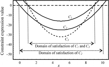
If a constraint expression (C1) in the standard negative null forms, that is, C1 ≤ 0, is greater than another, then the first constraint dominates the second. This is the basis for the CDM (Papalambros & Wilde, 1980). To illustrate this method consider two constraints C1 and C2, as shown in Figure 2, which are satisfied when the constraint expression is negative valued. Constraint C1 is negative and hence satisfied for values of x, 1 ≤ x ≤ 9. Constraint C2 has a broader range of satisfaction: it is satisfied for 0 ≤ x ≤ 10. To represent dominance relation, we use a stroked D symbol

, which was introduced in our earlier work (Rinderle & Deshpande, 2003) and is read “dominates,” to express the constraint dominance relation. Therefore, we can write

because any value of x that satisfies C1 will also satisfy C2. Furthermore, because the constraint expression value of C1 is always greater than that of C2, the condition (C2 − C1) ≤ 0 is satisfied for all values of x. Thus, the dominance relation,

, is identified using the CDM.

We find that and the condition (C2 − C1 ≤ 0) holds. Constraint but the condition (C2 − C3 ≤ 0) is not satisfied for all values of x.
Although this test is simple, determining whether the constraint difference is negative, either globally or for certain ranges of variable values, can be a challenging task. Interval arithmetic can be used for this purpose (Moore, 1966; Papalambros & Wilde, 1979; Alfeld & Herzberger, 1983); however, the interval arithmetic results are generally conservative, which gives rise to a need for more advanced methods.
The CDM gives a sufficient but not a necessary condition for dominance. Consider a new pair of constraints C2 and C3 as shown in Figure 2. Because the range of satisfaction of C3 is within the range of satisfaction of

. However, the constraint difference negativity condition (C2 − C3) ≤ 0, is not satisfied globally as C3 dips below C2 for certain values of x. In this case, the CDM fails to identify dominance, even though dominance exists.
2.2. The CTM
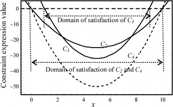
Because the constraint difference condition is a sufficient condition but not a necessary condition, there are cases such as the one shown in Figure 2 in which constraint dominance exists but the difference condition is not satisfied. One approach for constraint dominance identification in such situations is to transform the constraint expressions before taking the difference. This is the principle underlying the CTM (Rinderle & Krishnan, 1990). With this approach the constraints are transformed to forms for which the CDM can be used to identify dominance. If the transformation is sign preserving, then the regions of constraint satisfaction are unchanged and the results deduced from the transformed set of constraints are valid for the original constraints as well. For example, consider a pair of constraints involving C2 and C3. We transform C2 by multiplying by 2 to get a new constraint C4 as shown in Figure 3. The condition (C4 − C3) ≤ 0 is satisfied globally, and hence, according to the CDM

. The transformation of C2 to C4 is a sign-preserving transformation, and hence, the new constraint, C4, has the same range of satisfaction as C2. Therefore, this dominance can be extended to the original set of constraints C3 and C2, and one can infer that

.

The transformation of constraint C2 to C4 by multiplication by 2. The condition (C4 − C3 ≤ 0) holds globally, indicating that ; hence, .
Multiplication by a positive constant is the simplest (and least interesting) sign-preserving transformation. Many others are possible, but the complexity of finding transforms mitigates the greater power of this method.
2.3. The NSI method
The third method for dominance determination is based on the necessary and the sufficient intervals of the constraint variables. These intervals are always defined with respect to a constraint. A necessary interval on a variable with respect to a constraint is such that if a variable does not belong to this interval then the constraint is violated for all possible values of the other variables. A sufficient interval on a variable with respect to a constraint is such that if the variable belongs to this interval then the constraint satisfaction is guaranteed for all possible values of the other variables. If a necessary interval of one constraint falls completely within a sufficient interval of a second constraint, then that second constraint will be unconditionally satisfied whenever the first is, and therefore, the second constraint is dominated by the first constraint. This is the principle underlying the NSI method (Rinderle & Krishnan, 1990). By finding NSIs on constraints and by employing the above condition we can identify certain cases of constraint dominance.
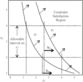
The NSI principle is illustrated in Figure 4. The figure shows two constraints, g1 and g2, each of which is a function of two variables x1 and x2. The a priori allowable interval on the variable x2 is known to be x2 ∈ [2, 4], and we want to determine the necessary and the sufficient intervals on x1 with respect to constraints g1and g2. Only values to the right of the dashed line indicated by N2 satisfy constraint g2; therefore, any value to the right of N2 is within the necessary interval with respect to g2. All values to the right of the line indicated by S1 satisfy g1, so these values are sufficient with respect to g1. Because the region demarcated by N2 is contained within the region demarcated by

.

The necessary interval on x1 with regard to g2, which is indicated by the arrow N2, lies within the sufficient interval on x1 with regard to g1, indicated by the arrow S1; therefore, .
Determining the necessary and the sufficient intervals is a challenge. In the most general case we may not be able to calculate these intervals directly; rather we repeatedly propose, test, and refine intervals to identify those that are necessary and sufficient (Rinderle & Deshpande, 2003, in press).
2.4. Characteristics and application strategies
There are three important characteristics pertaining to all three constraint dominance determining methods. First, all three methods are based on simple mathematical principles. Although the test conditions might be difficult to evaluate, for example, the constraint difference negativity test, the underlying principles are simple. Second, all the methods give conditions that are sufficient but not necessary to identify dominance, that is, the failure of these tests does not indicate the absence of dominance. Third, as observed in Rinderle and Deshpande (in press), the CDM and the NSI method present two distinct approaches for dominance determination. Although the CTM affords a unique set of properties, its underlying principle for dominance determination is the CDM. One can also consider the CDM as a special case of the CTM with transformation function as identity transformation. We preserve the notion of three distinct methods because the CTM is useful when the CDM is not. The differences among the methods lead to advantages for each method in circumstances that depend on the nature of the constraints and the extent of the design space.
These characteristics suggest that to bring out the true constraint dominance relations we will benefit from intelligent strategies to apply these methods in complex design problems. We may have to apply these methods in combination with each other and also with other constraint reasoning techniques such as monotonicity analysis. As discussed in Rinderle and Deshpande (in press), we may have to divide the design space into smaller spaces and test dominance over each space. Because each method gives a sufficient condition, it is possible for a method to identify dominance not identified by other methods. This suggests that we may have to apply these methods iteratively. In addition, because all the methods employ distinct approaches for dominance determination each method reveals different information, for example, one method may identify dominance but not give any useful insight into the design problem, while another method might. In this paper we present, with the help of the design problem, strategies to synergistically employ the dominance identification methods. We also present a novel approach for dominance determination that involves utilizing the transitivity property of the dominance relation.
For a complex design problem involving multiple constraints it might be a challenge to pick a pair of constraints to test for dominance. A simple strategy is to test for dominance in all possible pairs of constraints, but this is not an efficient strategy and may not reveal useful information quickly. In such situations a designer's previous experience can be useful in picking candidate constraints to test for dominance. In addition, other constraint reasoning techniques can be used, for example, we will show in the following sections that monotonicity analysis is a useful tool to help select candidate constraints to test for dominance. In the following section we demonstrate intelligent strategies to employ these dominance determination techniques in a real-life design problem. We also present a novel approach for dominance determination, which is based on the transitive nature of dominance.
3. ILLUSTRATION WITH A DESIGN PROBLEM
In this section we illustrate, with the help of a real-life design problem, the types of interactions and relationships we want to explore and strategies for the application of the dominance determining methods. We lay out the analysis for one configuration of the design and demonstrate that the dominance determination leads to the optimal design solution but also provides useful insight, which leads to effective decisions at the conceptual stage of the design.
3.1. Design problem description
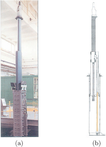
The task is to design a direct drive electric actuator as an alternative to the existing hydraulic cylinder drive of a universal modular mast (or periscope hoist assembly) of a submarine as shown in Figure 5. The current hydraulic cylinder is approximately 4.09 m long and is 16 cm in diameter. A stroke of approximately 3 m is required from the potential actuator, which results in an effective allowable actuator length of 1.09 m. The current hydraulic actuator acts through a pulley/cable arrangement to raise the mast into the required position. It generates a force ranging from 13,000 to 30,000 N during various stages of its operation. Viable alternatives to hydraulic actuation must fit within the existing envelope of the hydraulic cylinder, and must deliver equivalent forces.

The sensor assembly in the submarine. (a) The sensor hoisted on top of a telescopic mechanism and (b) a sketch showing the current hydraulic actuator that acts through a pulley/cable arrangement to raise the mast into the desired position. [A color version of this figure can be viewed online at www.journals.cambridge.org]
LSMs are potential design options. A number of configurations are possible for a LSM including single-sided, double-sided, or tubular LSMs. Each of these basic configurations gives rise to multiple design variations resulting from a variety of configuration choices including moving magnet or moving coils, axial or circumferential gap flux, longitudinal or circumferential return flux, and so forth. All of these configurations have relative advantages and disadvantages. For example, a double-sided LSM has a larger force/volume ratio than a comparable single-sided LSM, and so forth. Thus, the choice of configuration is itself a primary design decision. With regard to the design steps suggested in Section 1(as represented in Fig. 1), a variety of LSM configurations form the viable options, and the first task is to select one of those. Deshpande and Rinderle (2001) have discussed the existing LSM design configurations and their relative advantages and disadvantages in detail. Based on a preliminary analysis we choose a tubular configuration with a set of magnets moving inside an armature for the universal modular mast (UMM) application. This is the most suitable of the existing configurations for the UMM application, because in this configuration the allowable cylindrical volume is utilized efficiently, and there are no unnecessary forces generated in the direction perpendicular to the direction of motion (Deshpande & Rinderle, 2001).
We carry out a design process to determine the feasibility of a tubular LSM to satisfy the design requirements. We use constraint reasoning techniques, especially the constraint dominance methods, to facilitate the design process. At this early design stage it is not only important to test the feasibility of a tubular LSM but it is also critical to gain physical insight into the design problem so as to bring about design improvements. We demonstrate how the dominance determination brings out physical insight and, less formally, we also show how the insight gained from this result leads to conclusions for alternative LSM configurations. Because the governing principles for all the different LSM configurations are quite similar, the physical insight gained from the tubular LSM analysis is applicable to other configurations as well.
3.2. Governing behavior and design constraints
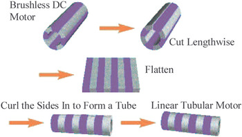
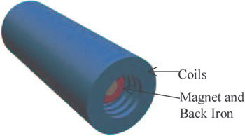
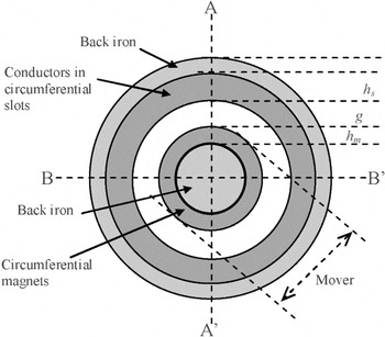
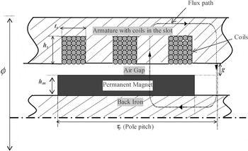
The LSM operates on the same working principle as that of a permanent magnet rotary DC motor (Basak, 1996; Gieras & Piek, 1999). As in a rotary motor there are two parts in a LSM; one is the set of permanent magnets and the other is the armature that has conductors carrying current. The permanent magnets produce a magnetic flux perpendicular to the direction of motion. The flow of current is in the direction perpendicular to both the direction of the motion and the direction of the magnetic flux. Figure 6 shows how a permanent magnet DC motor can be “unrolled” and “rerolled” in a different direction to form a tubular LSM. Figure 7 shows a tubular LSM. In this configuration the armature is a hollow cylinder with the conductors forming rings in the slots. The magnets form a shorter member that moves inside the armature. Figure 8 shows the cross-sectional view of the tubular LSM, and Figure 9 shows another cross-sectional view of a small length of the tubular LSM. In this view the outside surface of the motor is along the top of the figure and the direction of the motion is horizontal. As can be seen in Figure 9, the flux path in the gap between the magnets and the armature is radial, that is, vertical in the figure. The direction of the current flow is in and out of the paper. The force is produced by the interaction of the magnetic field with the currents. The force can be calculated using the so-called Bli law, which says that the force is the product of the flux density (B), the length of the conductors (l), and the current through the conductors (i). To increase the force one needs to either increase the flux density, the length of the conductors, or the total current. At the same time one has to consider the inherent as well as external limitations that can be represented as constraints.

The configuration change from a rotary DC motor to a tubular LSM (Boldea & Nasar, 1999). [A color version of this figure can be viewed online at www.journals.cambridge.org]

A tubular LSM with a moving magnet inside stationary coils. [A color version of this figure can be viewed online at www.journals.cambridge.org]

A cross section of a tubular LSM (not to scale). Magnets with the back iron form the mover that moves inside the armature formed from conductors inside the slots and back iron.

A cross section of approximately a one-pole pitch length section of a tubular LSM (not to scale). This is half of the “cut-open” part of the tubular shape along the sections A–A′ as shown in Figure 8. A typical flux path through the magnet and the back iron is shown.
3.2.1. Heat constraint
In an LSM the current carrying conductors in the armature produce heat due to resistive losses. This heat, if not dissipated properly, may damage the permanent magnets. Heat may also cause melting of the conductor insulation, resulting in short circuits. A system consisting of a motor and its surroundings has a limited capacity for heat dissipation, and therefore heat generation must be limited. The preliminary calculations for the LSM show that approximately 4000 W of heat can be convected from the motor with the proposed arrangement of coils. We consider 4000 W as the upper limit on the heat dissipation rate. The amount of heat generated depends on the current flowing through the conductors and volume occupied by the conductors. Thus, the limit on heat dissipation sets limits on the conductor current and the size of the motor.
3.2.2. Radius constraint
Usually the geometry and the total volume available restrict the size of the LSM. This sets a limit on the number of current-carrying conductors of a particular size, the length of these conductors, and thus, indirectly constrains the force. For the LSM under consideration, the total radius and the length are both constrained. As can be seen in Figure 8, the total radial space of the LSM consists of the magnets, the air gap, the back iron in the circuit, and the conductor slots. The limit on the total radius sets limits on the sizes of these motor components.
3.2.3. Saturation constraint
Figure 9 shows the flux path in the cross-sectional view of the LSM. The flux in the motor flows through the magnets, the teeth, the magnet back iron, as well as the armature iron, forming a closed loop. The iron directs the flux in the closed path with minimum flux leakage. These ferrous components saturate, limiting the flux density. Once the iron is saturated, increasing the magnetic field strength is not useful, as it will not increase the flux and hence the force will not increase. This sets a limit on how much the magnetic field strength can be usefully increased. The tooth in the stator has the least cross-sectional area and will saturate first. We set the saturation limit such that the tooth does not saturate.
3.2.4. Demagnetization constraint
The magnets produce a magnetic field in the air gap between the magnets and the armature. At the same time the armature currents also produce a magnetic field. This armature current field counteracts the field produced by the magnets at certain stages of the motor operation. Very high values of the armature current will produce a very large opposing magnetic field that may demagnetize the magnets, thus permanently altering the motor performance. This is one more limit on the armature current.
3.2.5. Minimum force requirement
A survey into the existing linear motor product data shows that one linear motor manufacturer produces tubular motors of comparable physical size (cal). One of the motors is about one-third of the length and produces a force of 5000 N. Because it is desirable to generate a force greater than that available from any commercially available motor, we can base a minimum force constraint on this value. The benefit in doing so, because we seek to maximize force anyway, is that this constraint helps to establish a more modestly sized design space. The design of a LSM includes the process of determining the dimensions of the various parts of the motor that generate the maximum force while satisfying the constraints. The formulations for the force equation, heat, saturation, size, and demagnetization limits can be derived from the principles of electromechanical energy conversion.
3.3. Simplified mathematical problem formulation
Formal derivations of the mathematical expressions for the force generated in an LSM and the constraints are carried out in Deshpande (2002). The analysis is simplified with the following assumptions. Two variables, the current i through each conductor and the number of conductors ns in each slot, appear in three expressions, namely, the force expression, the heat constraint expression, and the demagnetization constraint expression. In all three expressions i and ns appear together as (i × ns). We replace these two variables by a single variable named slot current (ins) to simplify calculations. More simplifications are stated in Deshpande and Rinderle (2003). Based on the analysis presented in Deshpande (2002) and by employing the simplifications in Deshpande and Rinderle (2003), the objective and the constraints are shown Table 1, in which the constraints are expressed in a negative null form (g ≤ 0). All lengths are in meters (m), the slot current ins is expressed in amperes (A), and the flux density is expressed in Teslas (T). The units of the various constants in the equations are not shown explicitly.
The equations for the objective and constraints for LSM design problem

3.4. Interval propagation to refine variable intervals
The design process often involves many design variables related to each other through a multitude of constraints. Although exact values of the design variables are unknown a priori, previous experience, physical requirements, specifications, and so forth, will often constrain some of the variables to specified ranges. The propagation of design variable intervals is a way to take advantage of knowledge of the ranges of the design variables to infer the ranges of other design variables and design performance parameters such as cost and weight. For example, if we require that between 100 and 200 W of power be delivered to a resistive heater, and if the voltages available range from 10 to 20 V, we can employ interval propagation to conclude that the current will have to be in the range of 5–20 A. Interval propagation can be used to eliminate infeasible designs, to refine the design search space and to make more reliable design decisions (Sarma & Rinderle, 1992). A number of formal techniques are reported in the literature; for example, Hansen (2006) considers ways to use monotonicity to reduce refine intervals and Benhamou et al. (2000) present an algorithm to compute inner approximations of relations for interval constraints. More examples can be found in Sarma and Rinderle (1992), Davis (1987), Sarma and Rinderle (1991), Granvilliers et al. (1999), and Benhamou and Granvilliers (1996).
With the knowledge of the intervals on the variables and the constraints we determine refined intervals on the variables using the interval propagation method as explained above. For example, with the lower bound on the height of the magnet, hmmin = 0 m and the upper bound on the slot width, limited to the full maximum radius, tsmax = 0.009 m and the total radius constraint we determine a new upper bound on the height of the slot as hsmax = 0.05385 m. Thus, the new interval on hs is hs ∈ [0, 0.05385 m]. We carry out interval propagation based on bounds over all the constraints by explicitly solving the constraints using interval arithmetic. After eight iterations of interval propagation we determine new intervals as follows: ins ∈ [0, 1028] A, ts ∈ [0, 0.00564] m, hs ∈ [0, 0.04366] m, and hm ∈ [9.1 × 10⁻⁴, 0.08] m. At this point we stop the propagation as the subsequent cycles of propagation yield very small refinement in the interval.
3.5. Observations
The problem stated above is a multivariable, single objective, constrained optimization problem with five inequality constraints. As one can observe the constraints are highly nonlinear. To approach the solution of this problem one may need numerous iterations of an efficient optimization algorithm. Alternatively, we can employ the constraint reasoning techniques discussed before. We explore the relationships among these constraints and use these relationships to reduce the size of the problem and finally determine the solution to the problem.
Again, the objective of the design is to maximize the force produced by the LSM. This objective is monotonically increasing with ins, that is, as ins is increased the force increases for all possible values of all other variables. One would like to have a high value of ins to maximize the force. However, as ins increases we approach the limit of the heat constraint and the demagnetization constraint. Therefore, the extent to which ins can be increased is limited. Of course, one of these constraints is going to be violated first, that is, at a lower value of ins. If ins is kept below this value both the constraints will be satisfied. This constraint is the dominant constraint that is, the satisfaction of this constraint ensures the satisfaction of the other constraint, at least when the ranges on other parameters remain unchanged. Once the dominant constraint is determined and if it is globally dominant then the dominated constraint can be deleted from the problem.
4. DOMINANCE IN THE LSM PROBLEM
In this section we explore ways to identify dominance between the heat constraint and the demagnetization constraint in the LSM design problem. Our previous experience with motor design tells us that heat is often the most important issue in motor design and it sets limits on the motor performance. Keeping this in mind we test to determine if the heat constraint dominates the demagnetization constraint. It is important to note here that we are not making any assumptions about the dominance; rather, we are simply using our experience to help us determine which dominance should be tested first.
4.1. The CDM
We start with the simplest of the approaches, which is the CDM. To prove that the heat constraint dominates the demagnetization constraint with the CDM we have to show that the condition (g4 − g1) ≤ 0 is satisfied. For the allowable values on the variables one can evaluate the constraint difference using standard interval arithmetic (Moore, 1966) as (g4 − g1) ∈ [−∞, 3998]. Clearly, the constraint difference negativity condition is not satisfied. Thus, we conclude that the CDM is not useful to identify dominance between the heat and the demagnetization constraint.
4.2. The CTM
We next try the CTM to identify dominance between the two constraints. With this approach we transform the constraints before taking the difference. The goal is to apply sign preserving transformations that will simplify the constraint difference function. We observe from the CDM that the constants in the two constraints do not cancel out after subtraction. One way to achieve this is to perform positive scalar transformation with the constraints. In addition, the exponent of the variable ins is different in the two constraints. Transforming the constraints so that ins has the same exponent in both can lead to elimination of ins from the difference function, thus simplifying the analysis. Our strategy is as follows:
- We transform the heat constraint recognizing that if the two terms in the constraint expression are taken as X2 and (40,0000.5)2, then the constraint can be written as X2 − (40,0000.5)2 = (X − 40,0000.5)(X + 40,0000.5) ≤ 0. Because ins, hm, hs, and ts are positive, X must also be positive. Therefore, transformation by dividing the constraint by the positive definite quantity (X + 40,0000.5) will yield a new heat constraint with the same range of satisfaction as the original heat constraint.
- We then transform the demagnetization constraint by multiplying it by a scalar equal to (heat limit)0.5/(0.9 × Br). A positive scalar multiplication is a sign-preserving transformation.
- Finally, we take the difference of these two transformed constraints.
For ins > 0, using the above strategy we obtain a condition relating hm, hs, t. This condition is given by the following:

This difference of transformed constraints is simpler than the difference of the original constraints mainly because all terms involving ins are eliminated. One can find the range of the values that the above expression takes for the allowable values of the variables hm, hs, and ts as (g4t − g1t) ∈ [−∞, −724.88].1
Special purpose interval arithmetic relations are used to evaluate the intervals of square root functions.
4.3. The NSI method
We now use the necessary and the sufficient interval method in an attempt to identify dominance between the heat and the demagnetization constraint. Even though dominance has already been proven by the CTM we employ this method to study the relative advantages and disadvantages of the approaches. We first need to determine the necessary interval on ins with respect to the heat constraint and the sufficient interval on ins with respect to the demagnetization constraint. The heat constraint as well as the demagnetization constraint are monotonic with regard to all the variables for allowable values on the variables. We can utilize this property to determine the desired intervals.
By definition, a necessary interval on a variable with regard to a constraint is such that if a variable does not belong to this interval then the constraints violated for all possible values of the other variables. Because the heat constraint monotonically increases with hm and ins and monotonically decreases with ts and hs, the necessary interval on ins can be determined by solving the constraint equation g1 = 0 for maximum possible values of ts and hs and minimum possible value of hm. The greatest values that ts and hs can take are 0.00564 m and 0.04366 m, respectively. The smallest value that hm can take is 9.1 × 10⁻⁴ m. Solving g1 = 0 for ins with the above limiting values of hm, hs, and ts gives a new upper limit on ins as insmax = 1028 A. Hence, the necessary interval on ins with respect to the heat constraint is ins ∈ [0, 1028] A. Note that a formal basis for this logic is given in Rinderle and Deshpande (in press).
By definition, a sufficient interval on a variable with respect to a constraint is such that if the variable belongs to this interval then the constraint satisfaction is guaranteed for all possible values of the other variables. Because the demagnetization constraint monotonically increases with ins and monotonically decreases with hm, the sufficient interval on ins can be determined by solving the constraint equation g4 = 0 for the minimum possible value of hm. Solving g4 = 0 for ins with the above limiting value of hm gives a new upper limit on ins as insmax = 1590 A. Thus, the sufficient interval of ins with respect to the demagnetization constraint is ins ∈ [0, 1590] A.
The necessary interval on ins with respect to the heat constraint lies completely within the sufficient interval on ins with respect to the demagnetization constraint. This means the satisfaction of the heat constraint ensures the satisfaction of the demagnetization constraint. Hence, the heat constraint dominates the demagnetization constraint.
Note that determining the necessary and the sufficient intervals of one variable by solving the constraint equations at the limiting values of other variables is possible in this case only because the constraints are monotonic with respect to all the variables for the allowable values of the variables. For a more general discussion on this topic refer to our previous work (Rinderle & Deshpande, 2003, in press).
4.4. A novel approach: The transitivity test
Dominance identification can be simplified by introducing an intermediate constraint and employing transitivity to show dominance among the original constraints. We call this a transitive dominance test. The idea behind this approach is that if a constraint A dominates constraint B and if constraint B dominates constraint C then by transitivity A dominates C. Thus, dominance between two constraints A and C can be identified by introducing a new constraint B. Constraint B can be a purely mathematical expression and need not possess any significance from the design point of view. We now employ a transitivity test in order to identify dominance between the constraints under consideration. Even though dominance has already been proven by the CTM and the NSI method we explore this approach to study the relative advantages and disadvantages of the approaches. For the heat and the demagnetization constraints we use the property of dominance transitivity twice. Our strategy is as follows:
- We find an intermediate form of the demagnetization constraint and prove that the intermediate form dominates the original demagnetization constraint.
- We find an intermediate form of the heat constraint and prove that the original heat constraint dominates the intermediate form.
- We show that the intermediate form of the heat constraint dominates the intermediate form of the demagnetization constraint, and therefore we claim that the original heat constraint dominates the original demagnetization constraint.
The choice of the intermediate forms of the constraints is critical to bring out the correct dominance relationship. The designer has a lot of freedom to choose the forms of the intermediate constraints, and she might have to try different forms for the intermediate constraints. The intermediate forms must be so chosen that the dominance between the intermediate forms and the original constraints as well as between the two intermediate forms can be determined easily. The general approach is to generate an intermediate form of constraint, test it for dominance, and if it fails iterate over this process. The fundamental driver of generation of a new constraint form, in an automated process, is to maintain the general structure of the original constraint, and add (or subtracts appropriate) a term, which, when combined with existing terms, will reduce the conservativeness of the interval arithmetic when applied to various subexpressions of the constraint. Another guiding principle is to add (or subtract) a term that simplifies the interval arithmetic. By maintaining the general structure it is easy to determine dominance relation between the original and intermediate forms of constraints. This is not a deterministic algorithm; however, it is easily implementable, thus many forms of intermediate constraints can be generated and tested quickly to deduce true dominance relation.
To determine dominance between the heat constraint and the demagnetization constraint we employed this method. We generated and tested different forms of intermediate heat and demagnetization constraints and after seven iterations we discovered intermediate forms that lead to a useful dominance relationship. Note that the intermediate forms were manually generated in this process, and we reached to useful forms by adding/subtracting terms that reduce the conservativeness of the interval arithmetic. Below we present generation and testing of intermediate forms of heat and demagnetization constraints that lead to dominance determination.
4.4.1. Intermediate form of the heat constraint
For the heat constraint (g) we choose an intermediate form that excludes the terms hs and ts from the numerator to get g1New, given as

One can use the CDM to show that the original heat constraint dominates the new constraint.

Because the variables hs, ts, and hm are always positive, the condition g1New − g1 ≤ 0 is satisfied for all allowable values of the variables; hence,

.
4.4.2. Intermediate form of the demagnetization constraint
For the demagnetization constraint, g4, we choose an intermediate form that excludes two terms hm, given as

We use the CDM to identify dominance between g4New and g4.

The allowable range of hm is hm ∈ [9.3 × 10⁻⁴, 0.08] m. The above expression is negative for all allowable values of hm. That means the condition g4 − g4New ≤ 0 is satisfied for all allowable values of the variables, and hence,

.
4.4.3. Dominance between the intermediate forms
To identify dominance between the two intermediate forms we use the following strategy:
- We transform the intermediate heat constraint from the form X2 − (40,0000.5)2 ≤ 0 to a form (X − 40,0000.5) ≤ 0. The logic behind this is explained in the previous section.
- We then transform the demagnetization constraint by multiplying it by a scalar equal to (heat limit)0.5/(0.9 × Br). A positive scalar multiplication is a sign preserving transformation.
- Finally, we take the difference of these two transformed constraints.
The intermediate heat constraint, g1New, dominates the intermediate demagnetization constraint, g4New, if the condition g4New − g1New ≤ 0 is satisfied.
This condition can be reexpressed as follows:

Therefore, if Eq. (6) is satisfied, then

. For all positive values of ins, ins ∈ [0, 1028] A, the condition in Eq. (6) can be transformed by dividing by the positive quantity (ins × 10−4) to attain

Equation (7) shows that the sufficient condition to identify dominance depends on the values of the hm and the slot area (hs × ts). The hm is proportional to the volume of the magnet in the motor and the slot area (hs × ts), is proportional to the volume of the copper in the motor. Thus, Eq. (7) shows that the dominance depends on the volume of copper and the volume of magnets in the motor. The allowable range of hs is hs ∈ [0, 0.0536] m, ts is ts ∈ [0, 0.0062] m, and the allowable range of hm is hm ∈ [9.3 × 10⁻⁴, 0.08] m. For these intervals the condition given by Eq. (7) is always satisfied. Hence, the heat constraint dominates the demagnetization constraint for all allowable values of the variables. The criterion given by Eq. (7) is not merely a mathematical relationship; it also has physical significance. It relates the volume of the magnets to the volume of the copper in the motor. The physical significance of the dominance condition is important because it may help the designer to make improvements in the motor configuration.
5. OPTIMAL SOLUTION USING MONOTONICITY ANALYSIS
Because the heat constraint dominates the demagnetization constraint for all the allowable values of the variables we delete the demagnetization constraint from the problem. We now have a new problem with four constraints and four variables, specifically ins, hm, hs, and ts.
5.1. Monotonicity analysis
An important property exhibited by many engineering problems is that the objective and the constraints are often monotonic, that is, strictly increasing or strictly decreasing with respect to some or all of the design variables. Based on this property of many design problems Wilde (1975) presented a technique called monotonicity analysis. This method was further extended by Papalambros and Wilde (1979, 1980). The underlying principle is that if the objective is monotonic with respect to a particular variable, then the variable must be bounded by one of the constraints; otherwise, there is no limit to the amount the objective could be improved. This constraint must be an active constraint. The authors put forth two theorems called monotonicity principles as tools for monotonicity analysis (Papalambros & Wilde, 1988). It is shown that the monotonicity analysis can be utilized in reducing the design space and in the best case reaching the optimum in a constraint bound problem.
The original motor problem is not monotonic because the demagnetization constraints not monotonic, and therefore, the monotonicity principle is not directly applicable. If we could discern, as is the case, that the demagnetization constraint is monotonic for positive values of hm, then monotonicity analysis would be applicable but of limited utility because it would be uncertain as to which constraints are active. After employing constraint dominance reasoning to eliminate the demagnetization constraint we can obtain strong results with monotonicity analysis. We can conclude
- by the first monotonicity principle that the heat constraint is active,
- by the first monotonicity principle that the radius constraint is active, and
- by the second monotonicity principle that the saturation constraint is active.
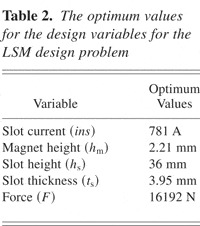
Because the heat constraint, the radius constraint, and the saturation constraint variables optimum values are active, they must be satisfied as equalities. Using these equalities one can convert this four-variable, four-constraint problem into a single variable problem with only one constraint, that is, the minimum force constraint. From this we get the objective as a function of hm. The constrained maximum of this function is at (hm)max = 0.0022 m. The maximum force at this value is Fmax = 16192 N. Table 2 gives the optimum values of the variables and the objective function.
The optimum values for the design variables for the LSM design problem

6. DISCUSSION
In the previous sections we have demonstrated the successful application of the dominance determining techniques to a LSM design problem. Following are some important observations based on our analysis.
6.1. Dominance and physical insight
Dominance condition can lead to physical insight, which is important because it may help the designer to make improvements in the configurations. In the LSM design context, if the volume of the copper and that of the magnets are such that Eq. (7) is satisfied, then the designer knows that the heat constraint dominates the demagnetization constraint. In such a situation, improvements in the design can be achieved by focusing on the heat dissipation, without worrying about the effects of demagnetization. The current configuration of the LSM stands good under this criterion, as it has moving magnets inside and coils lined outside along the length of the motor. This facilitates the transfer of the heat generated in the coils. The motor performance can be improved by increasing the heat dissipation rate. Introduction of fins or a water cooling mechanism on the outside of the motor are some of the ways to achieve this. Another important observation is that the optimum values of some of the variables may be difficult to achieve in practice, for example, it may be prohibitively expensive to have a very thin magnet as suggested by the optimal solution (2-mm thickness). This may direct the designer to consider other configurations such as stationary magnets, circumferential flux, and so forth, or may also suggest a need for relaxation of some of the constraints, for example, the radius constraint in the LSM case.
6.2. Dominance and configuration selection
The identification of dominance helps the designer to choose the best possible configuration. The heat constraint and the demagnetization constraint appear in all possible configurations of linear electric actuators including the LSMs and the linear induction motors. If one can show that the heat constraint is the critical limit then the decisions about the configurations can be made based on the amount of heat generated by these configurations. Such an insight and focus is important in the design process, and is otherwise achieved only through years of experience.
6.3. Synergy with other constraint reasoning techniques
With the LSM design example we have been able to demonstrate that the constraint dominance determination methods can be employed with other constraint reasoning methods. In the LSM motor example we first employed the interval propagation methods to establish refined intervals on the design variables that led to successful dominance determination. A major advantage of identifying dominance in the LSM design problem is it facilitated the use of monotonicity analysis for the given set of constraints. Using the arguments of monotonicity analysis one could find an optimal solution for the problem without complicated computations. The applicability of the monotonicity analysis is limited to the problems with a monotonic objective and monotonic constraints over the entire range of the variables. Hence, the strategies used in this problem may not work directly for more general engineering design problems. Nevertheless, this design exercise shows that reasoning with constraints can reduce the design space without complex computations, and may lead directly to a complete solution; and the combination of these methods affords advantages that are not obtained if the methods are applied individually.
6.4. Choice and implementation of dominance tests
As discussed in Section 2, dominance tests are based on distinct criteria and afford distinct advantages and disadvantages. In case of the LSM design problem, three different tests are employed to find the same dominance result; however, the manner in which the dominance is identified by these tests is quite different. With the CTM the transformation of the constraints resulted in a simplified constraint difference but finding the effective transformation is not easy. For the NSI method we identified dominance by comparing the necessary and the sufficient intervals on a variable with respect to the two constraints. The intervals are determined based on the refined ranges of the variables. For the transitivity test we introduced two new constraints and repeatedly applied the CDM and the CTMs to show dominance. This is more complicated than the NSI method and the CTM. On the positive side the transitivity test gives rise to a criterion that is sufficient to prove dominance. The criterion is not merely a mathematical relationship; it also has physical significance. It relates the volume of the magnets to the volume of the copper in the motor.
Choice of the correct dominance test for a design problem is challenging. In our previous work (Rinderle & Deshpande, 2003, in press) we have discussed many issues related to comparison of and selection of dominance tests. Our limited experience has shown that none of the methods is generally superior to the others. The best method depends on the constraints and on the design space. Furthermore, we believe that there is synergism among the methods; that is, in a design problem with a variety of types of constraints and with a continuing refinement of the design space, the opportunistic application of a combination of methods is significantly superior to the repeated application of any single method (Rinderle & Deshpande, 2003, in press).
For the conceptual design stage we do not have reliable methods for generating and testing configurations. Reasoning with constraints, especially constraint dominance based analysis, provides a mean to assist the designer in the conceptual design by emphasizing on the critical design issues. The dominance determining methods are not merely numerical tests, and are hard to implement manually for complex design problems. They require involved computer algebra methods, for example, in the case of the CTM determining and testing transformed is challenging. We believe that with the state of the art in computer algebra algorithms these tests are implementable.
6.5. Dominance determination as part of a computer tool
The dominance determining techniques and the strategies for their employment as presented in the previous sections are amenable to be programmed, at least, partially. All the dominance identification methods are founded on mathematical tests that can be programmed easily. The distinct nature of each test and the sufficiency criteria given by all the tests suggest that to determine the true dominance these methods need to be applied iteratively. As demonstrated in the example problem and also in our previous work (Rinderle & Deshpande, in press), in many cases an opportunistic subdivision of the design intervals and an intelligent choice of constraint combinations facilitates dominance identification. In some cases it is useful to introduce purely mathematical constraint equations, as in the case of the transitivity test in the LSM problem, to determine dominance. We have also demonstrated synergy between the dominance determining techniques and other constraint reasoning methods, which themselves are programmable. These characteristics suggest that the dominance determination techniques are suitable for automation and will need to be programmed for efficient implementation and can be part of a computer tool. Of course, algorithms for a number of steps such as choosing transforms must be developed, and initially will probably benefit from user input. We expect that the steps in this seemingly subjective process can be automated, for example, quickly running dominance checks among all pairs of constraints with CDM or generating a standard set of sign-preserving transformations, and so forth. Development of tools will be especially advantageous to assist the designer in the conceptual stage of the design.
7. CONCLUSIONS
Identifying dominance among constraints can assist the designer in various stages of design. In the conceptual stage it can help to focus attention on the most important design issues, and in the analytical stage it can lead to simpler solutions. Three constraint dominance determining methods are reported in the literature. The underlying approaches for each of the methods are different, which results in distinct characteristic strengths and weaknesses of these methods. With the help of the design problem we demonstrate strategies to synergistically employ the dominance identification methods. Specifically, we present an approach that utilizes the transitive nature of the dominance relation. It is shown that for the design of a tubular LSM, intelligent use of the dominance determining techniques, along with other CRM leads to an optimal solution without complicated computations. The identification of dominance provides insight into the design of linear actuators, which may lead to effective decisions at the conceptual stage of the design. We show that the dominance determination methods can be synergistically employed with other CRM such as interval propagation and monotonicity analysis to achieve an optimal solution for a particular design configuration of the linear actuator. The dominance determining methods and strategies for their employment are amenable to automation and can be part of a suite of tools available to assist the designer in detailed as well as conceptual design stages.