Introduction
In applications such as security screening, medical imaging, and radiometry, to name but a few, it is important to focus the energy in the millimeter-wave range to benefit both the nonionizing character of millimeter waves and their millimeter resolution [Reference Ettorre, Pavone, Casaletti, Albani, Mazzinghi, Freni, Boriskin and Sauleau1].
In this context, nondiffracting waves [Reference Hernández-Figueroa, Zamboni-Rached and Recami2], especially Bessel beams and their polychromatic version, i.e., X-waves, are gaining much attention in the millimeter-wave community due to their remarkable focusing features [Reference McGloin and Dholakia3]. Indeed, nondiffracting waves do not undergo diffraction within a certain depth of field. This is a striking difference with respect to more conventional beams and pulses such as Gaussian beams [Reference Deschamps4] and pulses [Reference Norris, White and Schrieffer5,Reference Ziolkowski6], or complex-source beams [Reference Tsitsas, Valagiannopoulos and Nosich7–Reference Tagirdzhanov, Blagovestchenskii and Kiselev9] and complex-source pulsed-beams [Reference Heyman and Steinberg10,Reference Heyman and Felsen11], that gradually spread their energy as they propagate. It is worth noting that Gaussian beams and pulses are equivalent to a paraxial complex spherical wave, whereas nondiffracting waves are generalizations of complex-source wavefields retaining bidirectional spectra [Reference Tagirdzhanov, Blagovestchenskii and Kiselev9,Reference Heyman12,Reference Kiselev13].
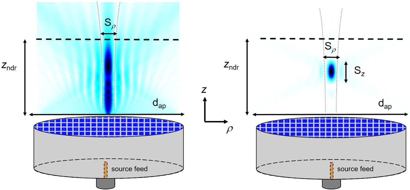
Bessel beams [Reference Durnin, Miceli and Eberly14], as well as X-waves [Reference Fuscaldo, Pavone, Valerio, Albani, Ettorre and Galli15], are able to maintain their nondiffractive character along the axis of propagation for a large distance (commonly known as nondiffractive range), as experimentally demonstrated in optics [Reference Saari and Reivelt16,Reference Sõnajalg, R'atsep and Saari17] and acoustics [Reference Ziolkowski, Lewis and Cook18,Reference Lu and Greenleaf19]. Interestingly, while Bessel beams are focused only along the transverse axis, X-waves are focused along both the transverse and the longitudinal axis (see Fig. 1).
Comparison between Bessel-beam launchers and X-wave launchers. On the left-side, a Bessel-beam launcher generating a transversely focused Bessel beam with transverse spot size  $S_\rho $. The transverse profile is maintained along the longitudinal axis up to the nondiffractive range z ndr. On the right side, the same device acts as an X-wave launcher in the time domain. The propagation of a focused X-wave is captured at a given time. Differently from the Bessel beam, the X-wave is confined also along the longitudinal z-axis where it exhibits a longitudinal spot size S z considerably narrower than z ndr.

Although Bessel beams have been experimentally generated in the microwave and millimeter-wave range (see, e.g., [Reference Li, Alici, Caglayan and Ozbay20–Reference Comite, Fuscaldo, Podilchak, Re, Guillamón-Gómez Buendía, Burghignoli, Baccarelli and Galli24]), experimental results for X-waves are very recent [Reference Chiotellis, Mendez, Rudolph and Grbic25,Reference Comite, Fuscaldo, Podilchak, Gómez-Guillamón Buendía, Re, Baccarelli, Burghignoli and Galli26]. The reason for this lack of experimental results was motivated in [Reference Fuscaldo, Pavone, Valerio, Albani, Ettorre and Galli15]. There, the development of an original theoretical framework allowed the derivation of several physical insights on the problem. The proposed analysis revealed that the design of an efficient X-wave launcher (i.e., able to focus energy along both the transverse and the longitudinal axis) usually requires a moderate wavenumber dispersion, a wide fractional bandwidth, and an electrically-large aperture. These requirements actually limit the class of suitable planar devices at millimeter waves to those using holographic approaches [Reference Fuscaldo, Pavone, Valerio, Albani, Ettorre and Galli15,Reference Pavone, Mazzinghi, Freni and Albani27] and leaky-wave techniques [Reference Comite, Fuscaldo, Podilchak, Gómez-Guillamón Buendía, Re, Baccarelli, Burghignoli and Galli26,Reference Fuscaldo, Comite, Boesso, Baccarelli, Burghignoli and Galli28]. In those works, the design process takes advantage of the concept of metric of confinement introduced in [Reference Fuscaldo, Pavone, Valerio, Albani, Ettorre and Galli15]. The design criteria adopted in [Reference Fuscaldo, Pavone, Valerio, Albani, Ettorre and Galli15,Reference Fuscaldo, Comite, Boesso, Baccarelli, Burghignoli and Galli28] will be clearly outlined in this paper.
On this basis, we provide here a more general criterion for designing X-wave launchers. It is shown that an electrically large aperture is not theoretically required to focus energy along both directions. Using the results recently outlined in [Reference Fuscaldo, Pavone, Valerio, Galli, Albani and Ettorre31], we show that the aperture size reduction dictates a larger fractional bandwidth.
The paper is organized as follows. In the section “Introduction”, the focusing features of X-waves are briefly outlined. In the section “Nondiffractive features of X-waves”, we review the concept of metric of confinement and discuss some original aspects relevant for specific millimeter-wave applications. In the section “Alternative criteria for electrically small apertures” the criteria for designing electrically small apertures are discussed. The section “Design of X-wave launchers” reports some practical design examples of X-wave launchers based on holographic approaches and leaky-wave techniques. Finally, conclusions are drawn in the section “Conclusion”.
Nondiffractive features of X-waves
X-waves can be obtained as a spectral superposition of Bessel beams with the same axicon angle [Reference Hernández-Figueroa, Zamboni-Rached and Recami2] over a certain frequency bandwidth Δω. Throughout the paper, we consider only spectrally-flat X-waves, i.e., we tacitly assume a uniform frequency spectrum. Under this assumption, an X-wave can be expressed as
 $$ \chi(\rho,z,t)=\int\nolimits_{\Delta\omega}J_0(k_\rho(\omega)\rho)e^{-jk_z(\omega)z}e^{\,j\omega t}d\omega, $$
where J 0(·) is a zeroth-order Bessel function of the first kind, ω is the angular frequency, t is time,  $k_\rho $ and k z are the wavenumbers along the radial ρ and longitudinal z directions, respectively (related each other through the separation relation
 $k_0^2=k_\rho ^2+k_z^2$, where k 0 is the free-space wavenumber), and
 $\theta =\arctan [k_\rho (\omega )/k_z(\omega )]$ is the axicon angle. Therefore, any Bessel-beam launcher characterized by a negligible wavenumber dispersion over a certain frequency bandwidth can act as an X-wave launcher in time domain. Moreover, since X-waves are obtained from Bessel beams, they inherit their focusing features.
Specifically, X-waves are localized along the transverse axis and maintain their transverse spot size  $S_\rho $ up to the nondiffractive range
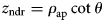 $z_{\rm ndr}=\rho _{\rm ap}\cot \theta $ [Reference Durnin, Miceli and Eberly14], where ρ ap is the aperture radius. In addition, X-waves are also localized along the longitudinal axis. However, the longitudinal spot size S z is narrow as long as a considerable fractional bandwidth is guaranteed [Reference Fuscaldo, Pavone, Valerio, Albani, Ettorre and Galli15]. This results from the definition of a suitable metric of confinement for X-waves [Reference Fuscaldo, Pavone, Valerio, Albani, Ettorre and Galli15,Reference Fuscaldo, Pavone, Valerio, Galli, Albani and Ettorre31], as we will review in the following paragraphs.
We note here that throughout the paper we always refer to zeroth-order X-waves, although higher-order X-waves are of extreme interest for their capability to carry orbital angular momentum [Reference Ornigotti, Conti and Szameit29,Reference Comite, Fuscaldo, Pavone, Valerio, Ettorre, Albani and Galli30].
Metric of confinement
The definition of metric of confinement states that X-waves are localized if and only if both their transverse S ρ and longitudinal S z spot sizes are smaller than the aperture diameter d ap = 2ρ ap and the nondiffractive range z ndr, respectively [Reference Fuscaldo, Pavone, Valerio, Albani, Ettorre and Galli15,Reference Fuscaldo, Pavone, Valerio, Galli, Albani and Ettorre31]. Hence, by introducing the following confinement ratios
 $$ C_\rho = S_\rho/d_{\rm ap}, $$
 $$ C_z = S_z/z_{\rm ndr}, $$
the definition of the following metric of confinement is straightforward:
 $$ C_{\rho,z} = \left\{ {\matrix{ 1 \hfill & {{\rm if} \max (C_\rho C_z) \gt 1}, \cr {C_\rho C_z} & {\rm elsewhere}.\hfill } } \right. $$
Clearly, when C ρ,z < 1, the resulting X-wave will be confined along both the radial and the longitudinal direction. Therefore, the value of C ρ,z gives a well-defined measure of the localization of the energy. Otherwise, when C ρ,z = 1 the X-wave would not be confined along the radial or the longitudinal direction.
Resolutions along the radial and longitudinal axis
For spectrally-flat X-waves, the expressions for  $S_\rho $ and S z and in turn
 $C_\rho $ and C z can be found in analytical closed form [Reference Fuscaldo, Pavone, Valerio, Albani, Ettorre and Galli15]. In the case of a nondispersive X-wave characterized by an axicon angle θ and generated at the carrier angular frequency ω 0 around a fractional bandwidth FBW = Δω/ω 0, S ρ and S z take the following expressions:
 $$ S_{\rho} = {\displaystyle{\,j_{0,1}\lambda_0} \over {\pi\sin\theta}}, $$
 $$ S_z = {\displaystyle{2\lambda_0} \over {{\rm FBW}\cos\theta}}, $$
where j 0,1 ≃ 2.405 is the first null of the zeroth-order Bessel function of the first kind, and λ 0 = 2π/k 0, with k 0 = ω 0/c 0 c 0 being the light speed in vacuum. From these expressions, we note that the transverse resolution  $S_\rho $ is lower-bounded by S ρ,a ≃ λ 0/1.3 (which is close to the Abbe diffraction limit for optical systems [Reference Born and Wolf32]). Conversely, the longitudinal resolution S z could be reduced arbitrarily, in principle, by increasing the fractional bandwidth. Nonetheless, planar radiating structures operating at millimeter waves are generally limited to 10–20% fractional bandwidths, thus S z is also practically lower-bounded by 2λ 0.
It is worth noting here that the axicon angle has an opposite effect over the longitudinal and the transverse resolutions, and thus it is not possible to narrow the resolution along both directions by solely changing the axicon angle.
From the expressions of  $S_\rho $ and S z, the confinement ratios
 $C_\rho $ and C z are readily found
 $$ C_{\rho} = {\displaystyle{\,j_{0,1}} \over {(\rho_{\rm ap}/\lambda_0)2\pi\sin\theta}}, $$
 $$ C_z ={\displaystyle{2\sin\theta} \over {(\rho_{\rm ap}/\lambda_0){\rm FBW}\cos^2\theta}}. $$
As for  $S_\rho $ and S z, it is manifest that the FBW is the only parameter that allows for improving the longitudinal localization without negatively affecting the transverse one.
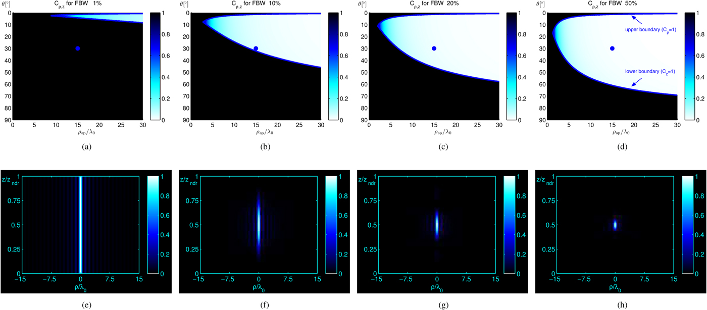
A numerical demonstration of this aspect is shown in Fig. 2. In Figs 2(a)–(d), the metric of confinement C ρ,z is reported as a contour plot of the two variables ρ ap/λ 0 and θ for values of FBW = 1, 10, 20, and 50%. The black region represents the pairs of values (ρ ap/λ 0, θ) for which the X-wave is not confined along at least one direction for a given FBW. This region is determined by the intersection of the two boundaries (see blue solid lines) that represent the condition for which  $C_\rho =1$ (upper boundary) and C z = 1 (lower boundary), respectively.
(a)–(d) The metric of confinement C ρ,z versus ρ ap/λ 0 and θ is shown for (a) FBW = 1%, (b) FBW = 10%, (c) FBW = 20%, and (d) FBW = 50%. In the black region  $C_\rho \gt 1$ or C z > 1, thus the resulting X-wave is not confined along both axes. The solid blue lines represent the boundaries for which
 $C_\rho =1$ (upper boundary) and C z = 1 (lower boundary). The two boundaries cross at
 $\theta =\theta ^\prime _{\rm eq}$ and
 $\rho ^\prime _{\rm eq}$. (e)–(h) Normalized field intensities |χ(ρ, z, t 0)|2/max|χ|2 versus ρ/λ 0 and z/z ndr for an X-wave generated with θ = 30° and ρ ap = 15λ 0 (see the blue dots in Figs 2(a)–(d)). The time t is set at the instant t 0 for which the X-wave peak has reached z = z ndr.
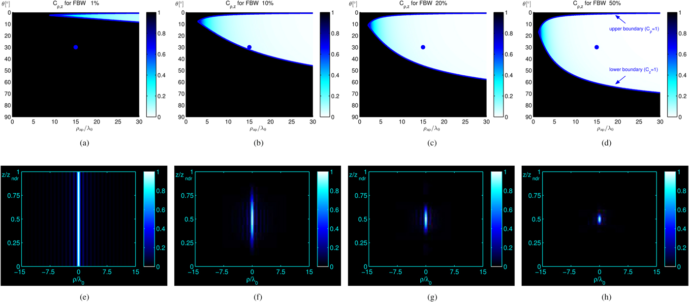
As is shown, the region within these two boundaries increases as the FBW increases. In other words, a pair of values (ρ ap/λ 0, θ) for which the X-wave is not confined for a certain FBW, might be confined for a higher FBW. This is corroborated by numerical results (see Figs 2(e)–(f)) considering a nondispersive X-wave characterized by the pair (ρ ap/λ 0 = 15, θ = 30°) (see blue dots in Figs 2(a)–(d)). As is shown, for low fractional bandwidths the X-wave is loosely localized along the longitudinal axis (the main spot has a “needle-like” shape), whereas it is tightly focused (the main spot has a “bullet-like” shape) for high fractional bandwidths.
Resolution and confinement equalization
For some applications, such as medical imaging, it could be more important to have the same resolution along both axes (i.e.,  $S_\rho =S_z$). Then, it is interesting to find the operating conditions equalizing the transverse and longitudinal resolutions. By equating the expressions of
 $S_\rho $ and S z, it is readily found that the equalization condition for resolution is obtained for θ eq:
 $$ \theta_{eq}=\arctan\left({\displaystyle{\,j_{0,1} {\rm FBW}} \over {2\pi}}\right)\simeq\arctan{(0.38\,{\rm FBW})}. $$
Inserting (9) into (5) we get an expression for the equalized spot-size
 $$ S_{\rm eq}=\lambda_0\sqrt{\left({\displaystyle{\,j_{0,1}} \over {\pi}}\right)^2 + \left({\displaystyle{2} \over {{\rm FBW}}}\right)^2}, $$
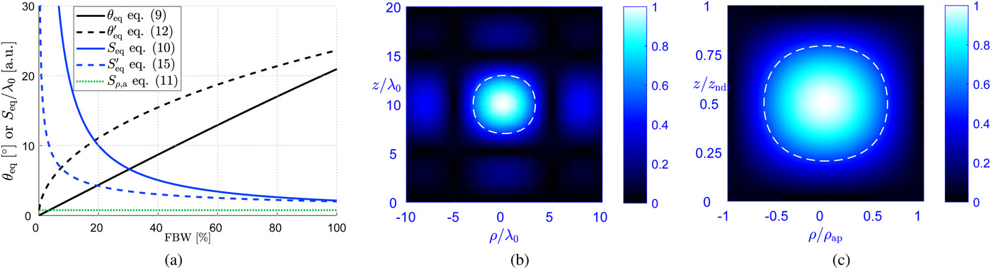
which represents the diameter of the resulting spherical-like pulse generated by the considered aperture. As expected, the minimum equalized spot-size is achieved for a theoretically infinite bandwidth. More precisely, S eq asymptotically approaches the limit λ 0/1.3 (represented as a green dotted line in Fig. 3(a)) as pointed out in the section “Resolutions along the radial and longitudinal axis”, i.e.,
 $$ \lim_{{\rm FBW}\to\infty}S_{\rm eq}=S_{\rho, a}\simeq\lambda_0/1.3. $$
In Fig. 3(a) we have reported equations (9) and (10) on the same plot to show the variation of θ eq and S eq, respectively, as functions of the fractional bandwidth in the range 0 ≤ FBW ≤ 1.
(a) θ eq,  $\theta ^\prime _{\rm eq}$ (in degrees) and S eq,
 $S^\prime _{\rm eq}$(normalized to λ 0) versus the fractional bandwidth in the range 0 ≤ FBW ≤ 1. The green dotted line identifies the asymptotic limit S eq ~ S ρ,a (b) Numerical demonstration of the resolution equalization condition (i.e., equation (9)). Normalized field amplitude |χ(ρ, z, t 0)|/max|χ| versus ρ/λ 0 and z/λ 0 for an X-wave generated with FBW = 20% and θ eq ≃ 4.38°. The aperture radius is fixed at ρ ap = 10λ 0 without loss of generality. (c) Numerical demonstration of the confinement equalization condition (i.e., equation (12)). Normalized field amplitude |χ(ρ, z, t 0)|/max|χ| versus ρ/ρ ap and z/z ndr for an X-wave generated with FBW = 20% and θ eq ≃ 11.06°. The aperture radius is fixed at
 $\rho _{\rm ap}/\lambda _0=\rho ^\prime _{\rm eq}$ to also show the validity of equation (14). Indeed, the field amplitude vanishes as ρ → ρ ap along the transverse axis, and z → z ndr along the propagation axis. In both (b) and (c) the time t is set at the instant t 0 for which the X-wave peak has reached z = z ndr/2. The white dashed line highlights the iso-line of the half-amplitude level.
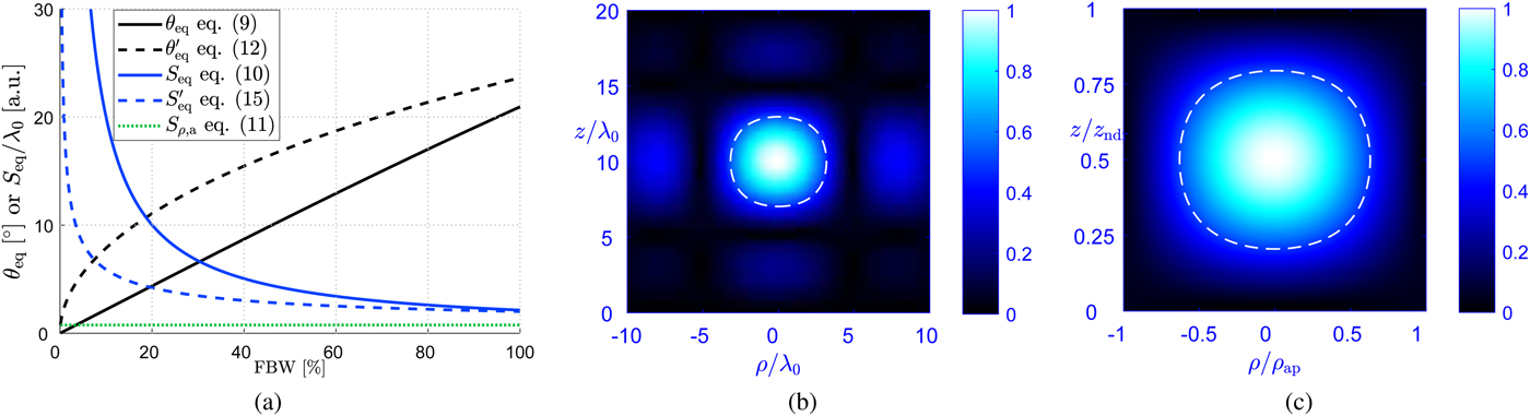
In order to numerically validate the equalization condition we generate an X-wave with a fractional bandwidth FBW = 20% at which corresponds θ eq ≃ 4° (see Fig. 3(a)). The contour plot of the generated field distribution over the ρ z-plane for this numerical example is reported in Fig. 3(b).
This equalization criterion gives the design rule to equalize the absolute resolutions (that is dimensionally a length). However, for some other applications, such as wireless power transfer, it could be more interesting to have the same relative resolutions (adimensional) with respect to the aperture diameter and the nondiffractive range, for the radial and longitudinal direction, respectively. This can be accomplished by equalizing the confinement ratios along both axes (i.e.,  $C_\rho =C_z$) in place of the resolutions (i.e.,
 $S_\rho =S_z$). In that case, equation (9) should be replaced by
 $$ \theta^\prime_{\rm eq}=\arctan\sqrt{{\displaystyle{\,j_{0,1} {\rm FBW}} \over {4\pi}}}\simeq\arctan{ (0.44\sqrt{{\rm FBW}})}, $$
where  $\theta ^\prime _{\rm eq}$ gives the condition for equalizing the confinement ratios rather than the resolutions. Inserting (12) into (7) we get an expression for the equalized confinement
 $$ C_{eq} = {\displaystyle{\lambda_0} \over {\rho_{\rm ap}}} {\displaystyle{2\pi} \over {\,j_{0,1}}} \sqrt{{\displaystyle{\,j_{0,1}} \over {2\pi}} + {\displaystyle{2} \over {{\rm FBW}}}}, $$
which depends on both the normalized aperture radius and the fractional bandwidth. However, from Figs 2(a)–(d) we note that a point exists for which the upper and lower boundaries of the metric of confinement (see blue lines in Figs 2(a)–(d)) meet at  $\theta =\theta ^\prime _{\rm eq}$ and
 $\rho _{\rm ap}/\lambda _0=\rho ^\prime _{\rm eq}$ with
 $$ \rho^\prime_{\rm eq} = {\displaystyle{\,j_{0,1}} \over {2\pi\sin\theta^\prime_{\rm eq}}}. $$
At this point (viz.,  $(\theta ^\prime _{\rm eq},\,\rho ^\prime _{\rm eq})$) we clearly have
 ${C_\rho =C_z=1}$. This point represents the limit condition of confinement equalization. In other words, for any aperture radius such that
 ${\rho _{\rm ap}/\lambda _0 \gt \rho ^{\prime }_{\rm eq}}$, the resulting X-wave will be efficiently confined and equalized (with respect to the relative resolutions), provided that
 $\theta =\theta ^\prime _{\rm eq}$. The absolute resolution achieved under the confinement equalization condition
 $S^\prime _{\rm eq}$ is obtained from equation (5), by replacing
 $C_\rho $ with C eq (see equation (13)), and reads
 $$ S^\prime_{\rm eq} = {\displaystyle{\pi\lambda_0} \over {\,j_{0,1}}} \sqrt{{\displaystyle{\,j_{0,1}} \over {2\pi}} + {\displaystyle{2} \over {{\rm FBW}}}}, $$
which clearly does not depend on ρ ap. The behavior of  $S^\prime _{\rm eq}$ as a function of FBW is reported in Fig. 3(a) in dashed blue lines.
In order to numerically validate the equalization condition for the relative resolutions we generate an X-wave with a fractional bandwidth FBW = 20% at which corresponds  $\theta ^\prime _{\rm eq}\simeq 11^\circ $ (see Fig. 3(a)). We then fixed
 ${\rho _{\rm ap}/\lambda _0=\rho ^\prime _{\rm eq}}$ to validate also equation (14). As a consequence, the generated X-wave should have a transverse spot size equal to the aperture diameter and a longitudinal spot size equal to the nondiffractive range (recall the definitions of
 $C_\rho $ and C z in equations (7)–(8)). This can be easily inferred from Fig. 3(c), where the contour plots over the ρ z-plane have been reported over the range 0 < ρ < ρ ap and 0 < z < z ndr.
Alternative criteria for electrically small apertures
In the previous section “Nondiffractive features of X-waves”, we focused on the equalization of the resolutions. Also, from the definitions of the confinement ratios, we demonstrated that X-wave launchers generally require an electrically large aperture, a considerable fractional bandwidth, and a low axicon angle [Reference Fuscaldo, Pavone, Valerio, Albani, Ettorre and Galli15]. In fact, from Figs 2(a)–(b), it appears that for low fractional bandwidths and electrically small apertures, an efficient confinement is possible only for few values of the axicon angle around 10°. However, the situation is rather different for higher fractional bandwidths (see Figs 2(c)–(d)), for which efficient confinement is possible for axicon angles up to 40°.
All these aspects can be recast in a more systematic way, by inspecting equations (7) and (8). In fact, from equation (7) one finds that the condition for having a transversely localized X-wave (i.e.,  $C_\rho \lt 1$) gives an aperture radius
 ${\rho _{ap}/\lambda _0 \gt (j_{0,1}/2\pi )\csc \theta }$, which is lower-bounded by the value j 0,1/2π ≃ 0.38. This means that even for such electrically small apertures, a minimum axicon angle θ min would exist beyond which the X-wave will be transversely confined
 $$ \theta \gt \theta_{\rm min} = \arcsin\left({\displaystyle{\,j_{0,1}} \over {2\pi\rho_{\rm ap}/\lambda_0}}\right). $$
However, since the metric of confinement is lower than 1 if and only if  $\max \{C_\rho ,\,C_z\} \lt 1$ (see equation (4)), the X-wave has to be also longitudinally confined (i.e., C z < 1) at θ min. Then, from equation (7), it results that the fractional bandwidth has to be greater than a minimum value FBWmin
 $$ {\rm FBW} \gt {\rm FBW_{\rm min}} = {\displaystyle{2\tan\theta_{\rm min}} \over {(\rho_{\rm ap}/\lambda_0)\cos\theta_{\rm min}}}. $$
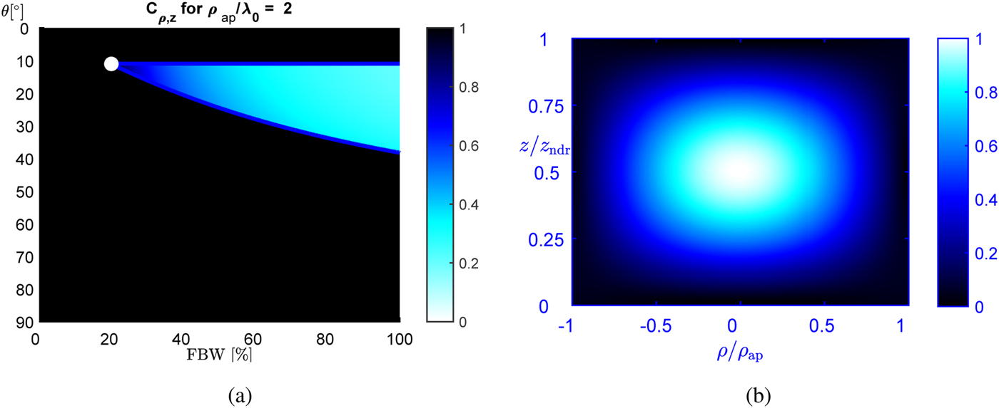
In this regard, in Fig. 4(a), we have reported the metric of confinement as a contour plot of the two variables θ and FBW for ρ ap/λ 0 = 2. As is shown, even for such an electrically small aperture, the conditions given by equations (16) and (17) identify a region where X-waves can be efficiently confined along both directions. In this numerical example, the limiting condition for the confinement is obtained for θ min ≃ 11° and FBWmin ≃ 20% (highlighted with a white dot in Fig. 4(a)) and corresponding to the intersection of the boundaries  $C_\rho =1$ and C z = 1 (see both blue solid lines in Fig. 4(a)).
(a) The metric of confinement C ρ,z versus FBW and θ is shown for ρ ap = 2λ 0. The blue solid lines represent the boundaries for which  $C_\rho =1$ and C z = 1. The two boundaries cross at FBW = FBWmin ≃ 20% and θ = θ min ≃ 11° (see the white dot). (b) Numerical demonstration of the minimum bandwidth condition for electrically small apertures (i.e., equations (16)–(17)). Normalized field amplitude |χ(ρ, z, t 0)|/max|χ| versus ρ/ρ ap and z/z ndr for an X-wave generated with FBWmin and θ min. The aperture radius is fixed at ρ ap = 2λ 0. The time t is set at the instant t 0 for which the X-wave peak has reached z = z ndr/2.
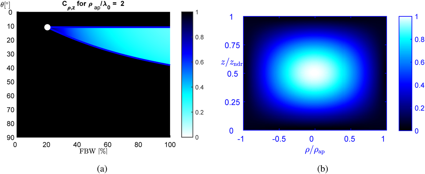
As for the previous equalization conditions, the numerical validation of equations (16)–(17) is performed by generating an X-wave with ρ ap = 2λ 0, FBW = 20%, and θ = 11°, corresponding to the operating conditions highlighted with a white dot in Fig. 4(a). The contour plot over the ρ z-plane for this numerical example is reported in Fig. 4(b). As is seen, the normalized field amplitude approaches the first null exactly at ρ = ρ ap and at z = z ndr. We note that the field localization along the transverse plane improves as θ is increased (see equation (7)). This increase in the value of θ, would in turn adversely affect the longitudinal confinement which, however, can be improved by increasing FBW (see equation (8)). More generally, for the considered fixed aperture radius, viz., ρ ap = 2λ 0, the pairs of θ and FBW values that grant an efficient confinement are represented by the bright region in Fig. 4(a).
Design of X-wave launchers
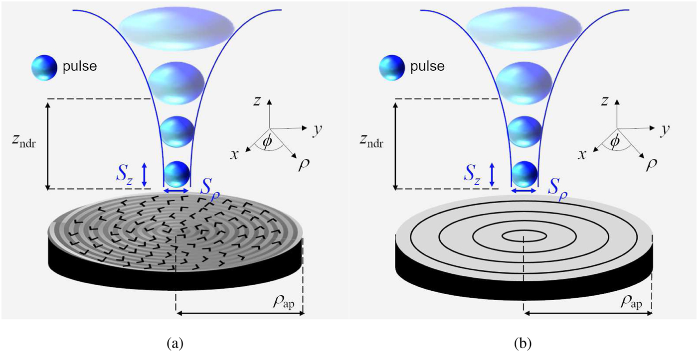
We consider here the design of two X-wave launchers both based on radial waveguides, but following two different approaches: a radial-line slot array (RLSA) antenna [Reference Pavone, Ettorre, Casaletti and Albani33] (see Fig. 5(a)), adopting a holographic design principle [Reference Albani, Pavone, Casaletti and Ettorre34], and a leaky-periodic radial waveguide (LPRW) [Reference Fuscaldo, Comite, Boesso, Baccarelli, Burghignoli and Galli28] (see Fig. 5(b)), exploiting leaky-wave theory [Reference Jackson, Oliner and Balanis35].
(a)–(b) An X-wave is launched from (a) an RLSA antenna and (b) an LPRW. As the X-wave pulse propagates beyond the nondiffractive range z ndr, the spot size increases and the intensity correspondingly decreases.
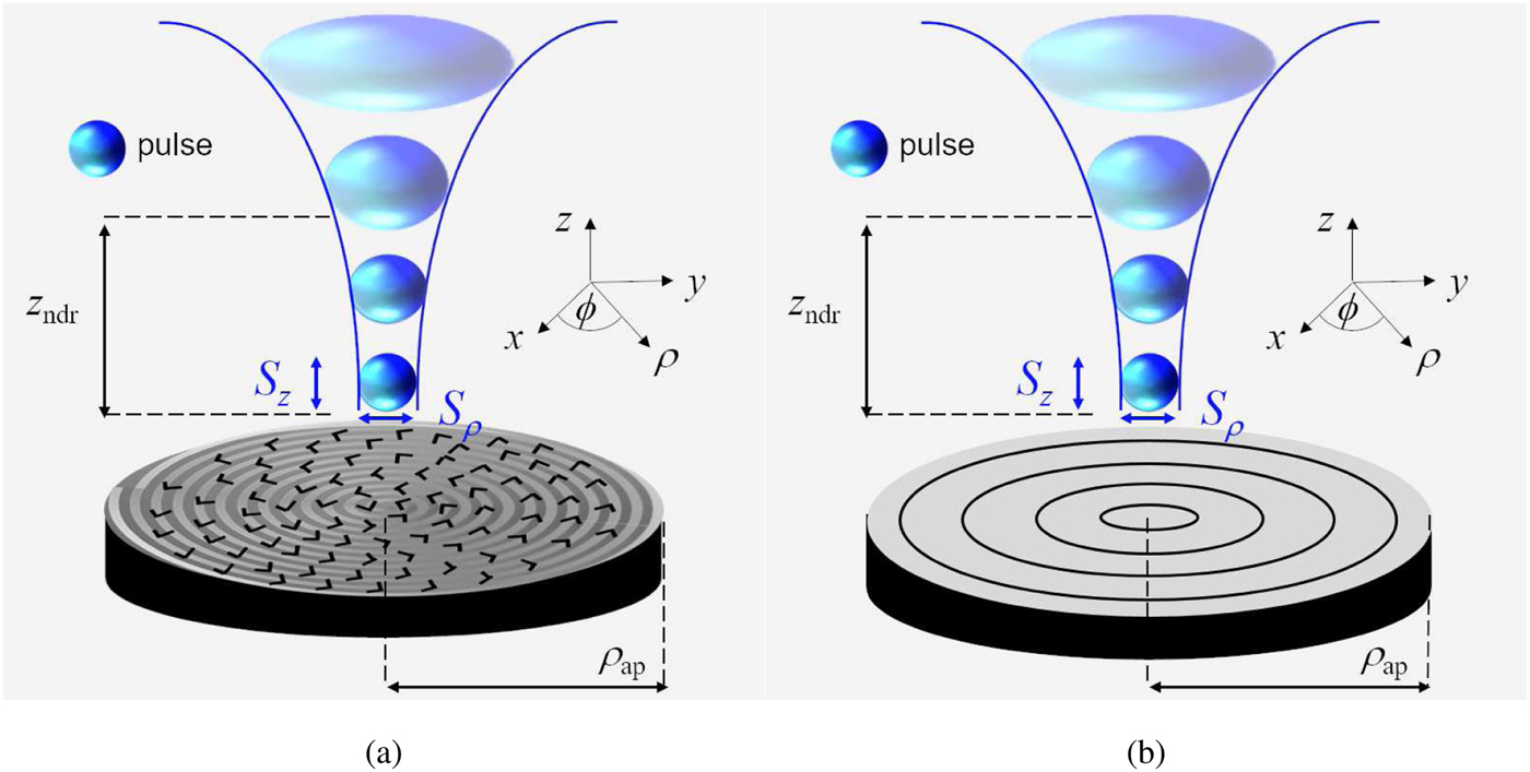
Among the various planar realizations of microwave and millimeter-wave Bessel-beam launchers (see, e.g., [Reference Li, Alici, Caglayan and Ozbay20–Reference Comite, Fuscaldo, Podilchak, Re, Guillamón-Gómez Buendía, Burghignoli, Baccarelli and Galli24] and references therein), the RLSA and the LPRW both possess wideband capabilities, and therefore they can also operate as X-wave launchers. The details for the accurate design of these devices such as X-wave launchers can be found in [Reference Fuscaldo, Pavone, Valerio, Albani, Ettorre and Galli15] and in [Reference Fuscaldo, Comite, Boesso, Baccarelli, Burghignoli and Galli28], for RLSA antennas and for LPRWs, respectively. Here we report the design of two X-wave launchers to validate the analysis developed in the previous sections.
RLSA antenna design
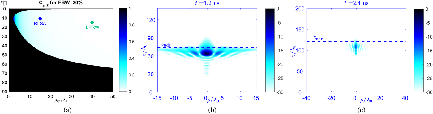
An RLSA antenna is a radial waveguide where slots are etched on the upper-plate in order to synthesize a prescribed aperture distribution for radiation (see Fig. 5(a)). Specifically, in [Reference Pavone, Mazzinghi, Freni and Albani27,Reference Pavone, Ettorre, Casaletti and Albani33], the radiating slots are arranged in a spiral path to synthesize an inward cylindrical-wave aperture distribution creating a Bessel beam. Once the aperture radius, the operating frequency, and axicon angle are fixed, the position and the size of each slot are optimized according to an in-house method-of-moments (MoM) code [Reference Albani, Pavone, Casaletti and Ettorre34]. Since the operating fractional bandwidth of an RLSA antenna easily achieves 10–20%, the efficient generation of X-waves is granted for several combinations of the design parameters, i.e., ρ ap and θ 0, as shown in Fig. 6(a), reporting the metric of confinement for FBW = 20%. Indeed, all pairs (ρ ap, θ) lying in the bright region of Fig. 6(a) can be used to launch efficiently confined X-waves.
(a) The confinement metric for a fractional bandwidth of 20%. A blue (green) dot represents the operating conditions of an RLSA(LPRW) design. (b)–(c) Contour plot of an X-wave launched by (b) an RLSA antenna and (c) by a LPRW with operating conditions as in (a). The X-wave is captured at a time instant for which the wavefront has traveled the distance z = z ndr/2).

As an example, we report in Fig. 6(b) the contour plot of an X-wave generated at f = 60 GHz by an RLSA with ρ ap = 15λ 0, and θ = 11° corresponding to the operating conditions of the blue dot in Fig. 6(a). The resulting X-wave is obtained through the numerical evaluation of the radiation integral and the Fourier-Transform of the spectral field as extensively discussed in [Reference Fuscaldo, Pavone, Valerio, Albani, Ettorre and Galli15]. This result will be commented further on, in comparison with the result obtained through an LPRW design.
LPRW design
An LPRW is a radial waveguide where the upper plate is replaced by an annular periodic metal strip grating (MSG). As shown in [Reference Fuscaldo, Comite, Boesso, Baccarelli, Burghignoli and Galli28], the period of the MSG is chosen so as to excite a backward leaky wave in the frequency range of interest. We recall here that leaky waves are characterized by a complex propagation wavenumber  $k_\rho =\beta -j\alpha $ where the imaginary part, the leakage rate, accounts for radiation losses [Reference Jackson, Oliner and Balanis35]. Backward (forward) leaky waves are those for which the group and phase velocities are in opposite (identical) directions [Reference Jackson, Oliner and Balanis35]. As a result, the backward character of the excited leaky wave allows for recovering the inward character required for the generation of a Bessel beam (see [Reference Fuscaldo, Comite, Boesso, Baccarelli, Burghignoli and Galli28] for a rigorous theoretical explanation). However, as opposed to RLSA antennas where the radiation efficiency is entirely controlled during the MoM optimization procedure [Reference Pavone, Ettorre and Albani23] , the radiation efficiency of an LPRW depends on the product between the leakage rate and the aperture radius of the device. As a consequence, a low value of the leakage rate (which is desirable to improve the focusing efficiency of the LPRW [Reference Fuscaldo, Comite, Boesso, Baccarelli, Burghignoli and Galli28]) demands for a relatively large aperture radius, in order to obtain a satisfactory radiation efficiency (commonly above 90% [Reference Comite, Fuscaldo, Podilchak, Re, Guillamón-Gómez Buendía, Burghignoli, Baccarelli and Galli24]).
As an example, we report in Fig. 6(c) the contour plot of an X-wave generated at f = 60 GHz by an LPRW with ρ ap = 40λ 0, and θ = 15°, corresponding to the operating conditions highlighted with a green dot in Fig. 6(a). At this point, it is worth to compare the results in Figs 6(b)–(c) obtained through an RLSA and an LPRW. As is manifest, the X-wave launched by an RLSA is less confined, but more intense than the one launched through by an LPRW. These two aspects have a clear physical explanation.
With regard to the confinement efficiency, it could be predicted from Fig. 6(a) that the operating conditions of the LPRW antenna would lead to a more confined X-wave with respect to the RLSA design. The former lay in a region of higher confinement (the color is brighter) according to the metric C ρ,z. However, it should be stressed that this improved confinement is only due to the larger aperture radius of the LPRW with respect to the RLSA. On the other hand, the confinement of the X-wave generated through the RLSA design can be improved by using a larger radiating aperture.
With regard to the different field intensities, we should comment on the role of the leakage constant in the LPRW. Indeed, the complex nature of leaky waves contributes to taper the aperture field distribution with an exponentially decaying function of the type exp (− αρ). As a consequence, the resulting X-wave does not present tails in the radial direction, but it experiences a higher field attenuation while propagating along the longitudinal direction (the interested reader may find a detailed analysis on these aspects in [Reference Fuscaldo, Comite, Boesso, Baccarelli, Burghignoli and Galli28]), with respect to the one generated through an RLSA design.
As a final comment we should discuss the energy tails surrounding the main spot of both X-waves. Indeed, an ideal X-wave would have tails outlining an X-shape (precisely, the axicon angle determines the intersection angle of the two branches forming the X-shape). Conversely, the X-waves reported in Figs 6(b)–(c) spread their energy even in other directions, partly masking the X-shape of the tails. This phenomenon is due to the dispersive features of an RLSA antenna and an LPRW, as shown in [Reference Pavone, Mazzinghi, Freni and Albani27] and [Reference Fuscaldo, Comite, Boesso, Baccarelli, Burghignoli and Galli28], respectively.
Conclusion
In this work, the design of efficient X-wave launchers has been discussed from an original perspective. By reviewing the concept of metric of confinement, we discussed alternative criteria for designing X-wave launchers that might be of interest for specific millimeter-wave applications. In particular, it has been shown that X-wave launchers can be designed to get either the same resolutions or the same confinement ratios along the longitudinal and transversal axes. Also, we discussed the possibility to design an efficient X-wave launcher without requiring an electrically large aperture. This comes at the expense of a larger fractional bandwidth. The discussion outlined in this work can be beneficial for the design process of X-wave launchers. The design of two X-wave launchers based on holographic and leaky-wave approach has been outlined to validate the results of the paper. The possibility to extend these results to the relevant case of dispersive X-waves is envisaged for future works.
Author ORCIDs
Walter Fuscaldo, 0000-0002-0773-6286.
 Walter Fuscaldo was born in Rome, Italy, in 1987. He received the B.Sc. and M.Sc. (cum laude) degrees in Telecommunications Engineering from Sapienza University of Rome, Rome, in 2010 and 2013. In 2017, he received the Ph.D. degree (cum laude and with the Doctor Europaeus label) from both the Department of Information Engineering, Electronics and Telecommunications (DIET), and the Institut d'Électronique et de Télécommunications de Rennes (IETR), Université de Rennes 1, Rennes, France, under a cotutelle agreement between the institutions.
In 2014, 2017, and 2018, he was a Visiting Researcher with the NATO-STO Center for Maritime Research and Experimentation, La Spezia, Italy. In 2016, he was a Visiting Researcher with the University of Houston, Houston, TX, USA.
His current research interests include propagation of leaky waves, surface waves and surface plasmon polaritons, analysis and design of leaky-wave antennas, generation of limited-diffraction limited-dispersion electromagnetic waves, millimeter-wave focusing systems, graphene electromagnetics, metasurfaces, and THz antennas.
Dr. Fuscaldo was a recipient of the Yarman-Carlin Student Award at the IEEE 15th Mediterranean Microwave Symposium in 2015, the Young Engineer Prize for the Best Paper presented at the 46th European Microwave Conference in 2016, IEEE AP-S Student Award, Chapter Center-Southern Italy in 2017, the Best Paper in Electromagnetics and Antenna Theory at the 12th European Conference on Antennas and Propagation in 2018, the “Barzilai Prize” for the best scientific work of under-35 researchers at the “22th National Meeting of Electromagnetics”. He was also awarded of the Publons Peer Review Award 2018 for placing in the top 1% reviewers in Engineering on Publons' global reviewers database, determined by the number of peer review performed from 2017 to 2018. In 2019, he organized with Dr. Mauro Ettorre the Special Session “Localized Waves: Science and Applications”, at the 41st Photonics & Electromagnetics Research Symposium. He is currently an Associate Editor for the IET Microwaves, Antennas & Propagation journal.
 Santi C. Pavone was born in Patti (ME), Italy, in 1988. He received the B.Sc. (summa cum laude) and M.Sc. (summa cum laude) degrees in electronics engineering from the University of Messina, Messina, Italy, in 2010 and 2012, respectively, and the Ph.D. degree (Doctor Europaeus) in information engineering and science (electromagnetics engineering) from the University of Siena, Siena, Italy, in 2015.
He was visiting Ph.D. student at the Institut d'Électronique et de Télécommunications de Rennes (IETR), Université de Rennes 1, Rennes, France, for 5 months in 2015. He is currently an Associate Researcher with the Laboratory of Applied Electromagnetics, University of Siena, Siena, Italy. His current research interests include fundamental electromagnetic theory, RADAR design at millimeter waves, high-frequency techniques, focusing systems, non-diffractive localized pulses, and leaky-wave reconfigurable antennas based on liquid crystals. Dr. Pavone was a recipient of the ESF Research Networking Programme NEWFOCUS Scholarship in 2015, and also of the IEEE Antennas and Propagation Society Student Award, Chapter Central-Southern Italy, in 2014. In 2017, he was a finalist for the Best Paper Award in Electromagnetics and Antenna Theory at the 11th European Conference on Antennas and Propagation, Paris. In 2018 he was co-recipient of the Best Paper Award in Electromagnetics and Antenna Theory at the 12th European Conference on Antennas and Propagation, London, UK.
 Davide Comite received the Master's degree (cum laude) in Telecommunications Engineering in 2011 and the Ph.D. degree in Electromagnetics and Mathematical Models for Engineering in 2015, both from Sapienza University, Rome, Italy, where he is currently a Postdoctoral Researcher. He was a visiting Ph.D. student at the Institute of Electronics and Telecommunications of Rennes, University of Rennes 1, France, from March to June 2014 and a Postdoctoral Researcher at the Center of Advanced Communications, Villanova University, PA, USA, from April to December 2015.
His scientific interests involve the study and design of dual-polarized leaky-wave antennas, 2-D periodic leaky-wave antennas, and the generation of non-diffracting waves and pulses. He is also interested in the study of the scattering from natural surfaces as well as the characterization of the GNSS reflectometry over the land, the microwave imaging and objects detection performed through GPR, and the modeling of the radar signature in forward scatter radar systems.
Davide was a recipient of the “Marconi Junior” Prize, awarded by “Fondazione Guglielmo Marconi” in 2012 to a young student author of a Master's degree thesis particularly relevant and important in Information and Communications Technology. He received an honorable mention in the frame of the “Minerva Award 2017”, assigned by Sapienza University and Fondazione Sapienza to postdoctoral researchers who carried out distinguished research activities. In 2017, Davide was a finalist of the Best Paper Award, Electromagnetics and Antenna Theory section, at the 11th European Conference on Antennas and Propagation. He has been a co-author of the Best Student Paper Award, at the SPIE Remote Sensing and Security+Defence International Symposia in 2017, and a co-recipient of the Best Paper Award, Electromagnetics and Antenna Theory section, at the 12th European Conference on Antennas and Propagation in 2018. Davide won the Barzilai Prize in 2018 for the best scientific work of under-35 researchers at the National Meeting of Electromagnetics (XXII RiNEm). In 2014 and 2017 he has been a recipient of a research grant assigned by Sapienza University to young researchers, in 2016 of a research grant for a short-term scientific mission to the Heriot-Watt University in the frame of the Cost Action IC1301, and in 2019 of a travel grant offered by the European Commission to attend the Living Planet Symposium 2019.
 Guido Valerio received the M.S. degree (cum laude and honorable mention) in electronic engineering in 2005, and the Ph.D. degree in electromagnetics in 2009, from La Sapienza University, Rome, Italy. From February to August 2008 he was a Visiting Scholar at the University of Houston, TX, USA. From 2011 to 2014, he was a researcher at the Institut d'Électronique et de Télécommunications de Rennes (IETR), France. Since September 2014 he is an Associate Professor in the Laboratoire d'Électronique et Electromagnétisme, at Sorbonne Université, Paris, France.
His scientific interests involve antenna design and numerical methods for wave propagation and scattering in complex structures; namely, periodic Green's function computation, modal properties of multilayered structures, full-wave methods for SIW, modeling of periodic structures with higher-symmetries.
In 2008 Dr. Valerio was the recipient of the “Leopold B. Felsen Award for Excellence in Electrodynamics.” In 2009 he was a finalist for the “Young Engineering Prize” at the European Microwave Conference. In 2010 he was the recipient of the “Barzilai Prize” for the best paper at the National Italian Congress of Electromagnetism (XVIII RiNEm). In 2014, he was the recipient of the RMTG Award for junior researchers presented at the IEEE Antennas and Propagation Society Symposium, Memphis, TN. In 2018, he was a co-author of the best paper in Electromagnetic and Antenna theory at the 12th European Conference on Antennas and Propagation, London, UK.
 Matteo Albani received the Laurea degree in electronic engineering and Ph.D. degree in telecommunications engineering from the University of Florence, Florence, Italy, in 1994 and 1999, respectively.
He is currently an Associate Professor with the Information Engineering and Mathematics Department, University of Siena, Siena, Italy, where he is also the Director of the Applied Electromagnetics Laboratory. From 2001 to 2005, he was an Assistant Professor with the University of Messina, Messina, Italy.
He coauthored more than 80 journal papers and book chapters, more than 200 conference papers, and five patents. His research interests are in the areas of high-frequency methods for electromagnetic scattering and propagation, numerical methods for array antennas, antenna analysis and design, metamaterials and metasurfaces.
Dr. Albani received the “G. Barzilai” Young Researcher Best Paper Award, at the XIV RiNEM, Ancona, Italy 2002, and the URSI Commission B Young Scientist Award at 2004 URSI EMTS, Pisa, Italy. He was Co-author and Advisor of the winners of the Best Paper Award, at the First European AMTA Symp. 2006, Munich, Germany and of the “3rd Prize Young Scientist Best Paper Award” 2010 URSI EMTS, Berlin, Germany. With his co-authors, he was awarded with the Antenna Theory Best Paper at the EuCAP 2014 in den Haag, the Netherlands and with the Antenna Theory Best Paper at the EuCAP 2018 in London, UK. He is a member of EurAAP and URSI and a Fellow of IEEE.
 Mauro Ettorre received a Laurea degree (summa cum laude) in Electrical Engineering, and a Ph.D. degree in Electromagnetics from the University of Siena, Italy, in 2004 and 2008, respectively. Part of his Ph.D. work was developed at the Netherlands Organisation for Applied Scientific Research (TNO), The Hague, the Netherlands, where he later worked as an Antenna Researcher. From 2008 to 2010, Dr. Ettorre was a Postdoctoral Fellow at Institut d'Électronique et de Télécommunications de Rennes (IETR), Université de Rennes 1, Rennes, France. In 2010 and 2016, he was a Visiting Scholar in the Radiation Laboratory, Department of Electrical Engineering and Computer Science, University of Michigan, USA. Since October 2010, he is a Research Scientist at the Centre National de la Recherche Scientifique (CNRS), within the IETR. In 2014, he assumed responsibilities for the multi-beam antenna activity for satellite applications in the joint laboratory between IETR and Thales Alenia Space, France. In 2015, he was an Invited Professor at the Tokyo Institute of Technology (TIT), Japan. Since 2016, he has been Secretary of the French National Committee for Scientific Research, Section 08 (micro- and nanotechnologies, photonics, electromagnetism), CNRS, Paris, France. Since 2017, he is an Associate Editor for the IEEE Transaction on Antennas and Propagation. In 2017 and 2018, he was a member of the best paper award selection committee for the IEEE Transactions on Terahertz Science and Technology.
Dr. Ettorre's research interests include the analysis and design of leaky-wave antennas, periodic structures, millimeter-wave antennas, non-diffractive radiation and localized waves, near-field focusing techniques, and wireless power transfer systems.
Dr. Ettorre received the Young Antenna Engineer Prize at the 2008 ESA Antenna Workshop in the Netherlands, the Innovation Award at 2018 ESA Antenna Workshop in the Netherlands and the Best Paper Award in Electromagnetics and Antenna Theory at the 2018 European Conference on Antennas and Propagation (EuCAP), London, UK.
 Alessandro Galli received the Laurea degree in electronic engineering and the Ph.D. degree in applied electromagnetics from the Sapienza University of Rome, Rome, Italy. Since 1990, he has been with the Department of Electronic Engineering (now Department of Information Engineering, Electronics, and Telecommunications) at Sapienza University of Rome. In 2000, he became an Assistant Professor, and in 2002 an Associate Professor with the Sapienza University of Rome, and he passed the National Scientific Qualification as a Full Professor in the sector of Electromagnetics in 2013. For the educational activities, he is currently teaching or co-teaching the courses of Electromagnetic Fields, Advanced Antenna Engineering, Microwaves, and Engineering Electromagnetics, for Electronics and Communications Engineering at the Sapienza University of Rome.
He has authored more than 300 papers on journals, books, and conferences. He holds a patent for an invention concerning a type of microwave antenna. His current research interests include theoretical and applied electromagnetics, mainly focused on modeling, numerical analysis, and design for antennas and passive devices from microwaves to terahertz: specific topics involve leaky waves, periodic and multilayered printed structures, metamaterials, and graphene. Other topics of interest involve geoelectromagnetics, bioelectromagnetics, and microwave plasma heating for alternative energy sources.
Dr. Galli was elected as the Italian representative of the Board of Directors of the European Microwave Association (EuMA), the main European Society of electromagnetics, for the 2010–2012 triennium and then re-elected for the 2013–2015 triennium. He was the General Co-Chair of the European Microwave Week, the most important conference event in the electromagnetic area at European level in 2014. Since its foundation in 2012, he is the Coordinator of the European Courses on Microwaves, the first European educational institution on microwaves. He is also a member of the European School of Antennas (ESoA). He is a member of the leading scientific societies of electromagnetics, and an Associate Editor of the International Journal of Microwave and Wireless Technologies (Cambridge University Press) and of the IET Microwaves, Antennas and Propagation (Institution of Engineering and Technology). He was a recipient of various grants and prizes for his research activity, the Barzilai Prize for the best scientific work of under-35 researchers at the 10th National Meeting of Electromagnetics in 1994, and the Quality Presentation Recognition Award at the International Microwave Symposium by the Microwave Theory and Techniques Society of the IEEE in 1994 and 1995. Based on a poll among about 300 attendants to the ESoA courses, in 2017 he has been elected ‘Best Teacher’ in a competition of more than 100 international speakers.