NOMENCLATURE
- b
-
distance between stringers
- c
-
chord, length
- cL
-
aerodynamic lift coefficient
- d, h
-
distances
- E
-
Young modulus
- F
-
Farrar factor
- G
-
shear modulus
- k
-
proportionality constant
- ks
-
ratio, stringers thickness vs. springs
- l(y)
-
lifting forces per unit, span
- m(z)
-
bending moments per unit, span
- p
-
pressure
- t
-
skin thickness
- ts
-
stringers thickness
- v
-
velocity
- x
-
distance
- α, θ
-
angles
- ρ
-
fluid, air, density
- σ
-
stress
- v
-
Poisson ratio
1.0 INTRODUCTION
This paper demonstrates the feasibility of an innovative morphing rudder that presents enhanced aerodynamic efficiency. This work includes the structural definition of the non-conventional rudder whose enhanced aerodynamic characteristics were previously analysed(Reference Castillo-Acero, Cuerno-Rejado and Gómez-Tierno1). The aerodynamic improvements that can be achieved with an unconventional morphing rudder have already been quantified. The geometry of such a rudder provides a continuous curvature function between the trailing edge, both sides of the vertical stabilizer fixed part and the rudder, and the function follows curving the rudder body itself. The curves on previous study were obtained by means of graphical approaches to achieve a theoretical shape. In this study, we develop a morphing feasible structure to obtain a close solution to the theoretical aerodynamic optimum shape.
Achieving the curved shapes needed to obtain the aerodynamic enhancements requires sufficient capacity on the actuation system. This capacity essentially translates into two parameters: the displacements required at different points, and actuator forces to maintain the shape under loading. While in recent years there have been numerous developments in the fields of actuators, e.g. shape memory, or multi-stable piezoelectric materials(Reference Barbarino, Bilgen, Ajaj, Friswell and Inman2-Reference Portela, Camanho, Weaver and Bond4), in this work we prefer to develop a system based on commercially available actuators. The focus of this study is on developing the structure based on articulated ribs with highly deformable panels, chord-wise direction, and enough stiffness and strength span-wise to able to sustain the internal loads per certification requirements. To complete the new rudder architecture, a highly deformable elastomeric rubber coating is required to provide non- permeability to air. The literature contains good examples of this type of structure(Reference Monner5), although its application is focused on developing a solution for wing spoilers where deflections are fairly lower (±15°) than in the rudder (±30°, the typical values for this study). This concept has been also refined for wing lift devices (flaps)(Reference Pecora, Amoroso and Magnifico6).
The present study includes two main objectives: the optimum articulated rib configuration geometry and the definition of the highly deformable skin panels. These panels are cell-skeleton-based and highly orthotropic. They are often called Poisson zero skeletons in the literature, defined as close-to-zero Poisson ratio panels based on stiffeners in one direction, and in the perpendicular direction, geometrical cells that behave as springs. Studies on these panels have been found for wind turbine blade applications(Reference Lachenal, Daynes and Weaver7-Reference Daynes and Weaver9). There are also studies of their introduction on aircraft, such as for active aero-elastics,(Reference Schweiger and Krammer10-Reference Gomez and Garcia12) or a more general overview(Reference Vocke, Kothera, Woods, Bubert and Wereley13).
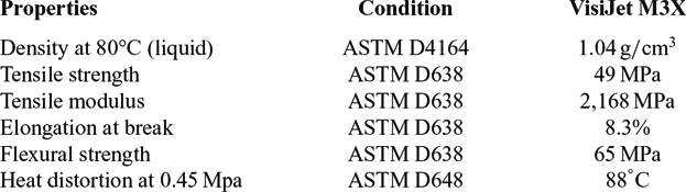
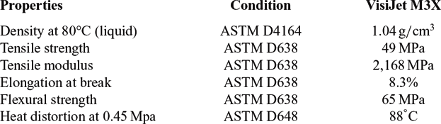
The approach for obtaining the equations to derive the optimum configuration has been the structural pre-sizing. The load case selected is the one-engine-out that usually is critical for the sizing of the rudder for commercial transport aircraft with pod-mounted engines under the wing. The articulated-ribs concept is based on aluminium 7X series riblets that rotate to provide the required shape. The turning law at each articulation and the riblets-length geometry is selectable. Different configurations for the zero Poisson highly deformable skeleton have also been considered. Then it is necessary to obtain stiffness/strength properties, both in-plane orthotropic E 1, E 2, G 12, v 12, v 21 and out-plane E 3, G 13, G 23, v 13, v 31 v 23, v 32. The raw material considered is Visijet M3 X properties in Table 1. This material can be easily processed in a commercially available 3D printing device and therefore can be defined as a printable material. A material is 3D-printable if can be the raw material for an additive layer manufacturing process.
Visijet M3 X 3D printable material properties(14)
The application of this type of morphing rudder means potential weight savings in commercial transport aircraft empennages, thus representing an important opportunity for aircraft OEMs and Tier 1 suppliers that design and build these types of structures. The more efficient the rudder, the smaller it can be and the less it will weigh. This is an important finding due to the trend in aeronautical research for more efficient aircraft with lower fuel consumption, as well as requirements for reduction of CO2 emissions.
2.0 METHODOLOGY
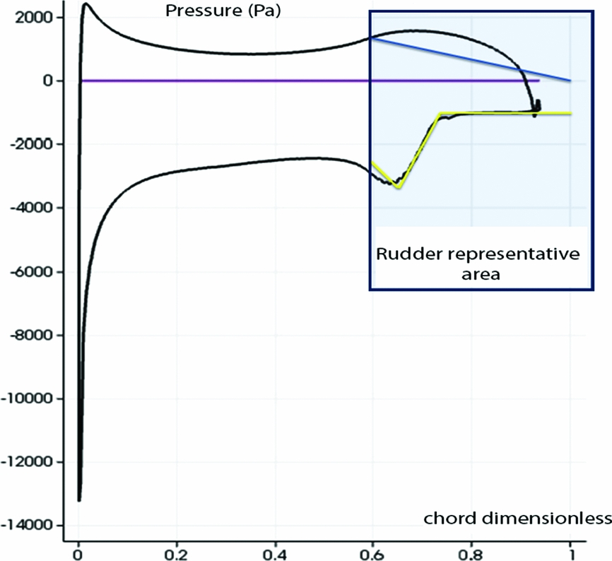
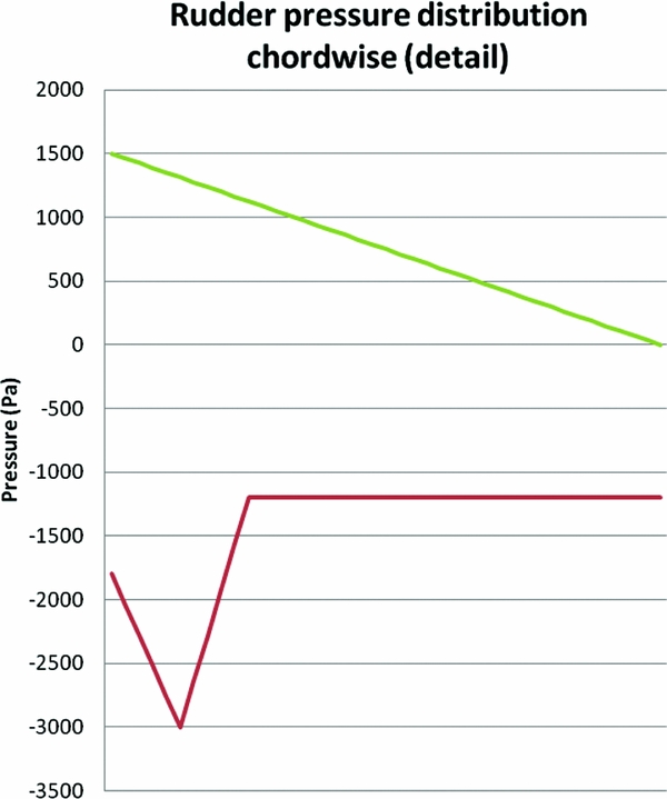
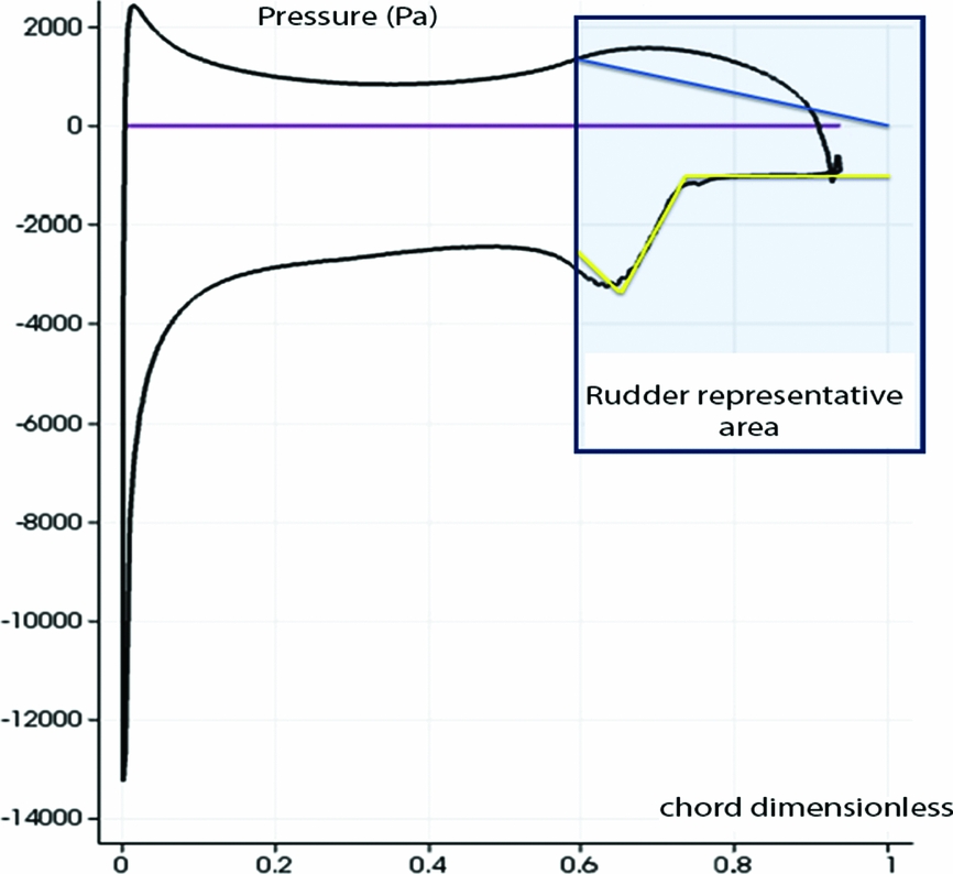
The methodology is based on the preliminary sizing of the new non-conventional rudder. The applied external loads considered come from previous studies(Reference Castillo-Acero, Cuerno-Rejado and Gómez-Tierno1) for the load case of engine failure during takeoff that requires maximum rudder deflection of 30°. In commercial transport aircraft under the wing engines pod configuration, this load case usually sizes the rudder. The load case of crosswind landing yields similar loading and practically the same order of criticality. From the previous study, the differential pressure distribution in the vertical tail plane section at one-third height Vertical Tail Plane (VTP) span has been obtained (Fig. 1). Then the loading at the morphed rudder with a linear approach is considered (Fig. 2).
Aerodynamic loads on the morphing rudder and rest of the vertical tail plane(Reference Castillo-Acero, Cuerno-Rejado and Gómez-Tierno1) section one-third height.
Aerodynamic loads model on the morphing rudder.

These aerodynamic loads are translated into:
-
• l(y): lifting forces per unit span length, in this case lateral ‘y’ forces
-
• m(z): ‘z’ bending moments per unit span length
(1) $$\begin{equation}l\left( y \right) = \frac{1}{2}\rho {v^2}c\mathop \sum \nolimits^ {c_l}\left( {{\raise0.7ex\hbox{${{x_i}}$} \!
/ \!\lower0.7ex\hbox{$c$}}} \right)\Delta \left( {{\raise0.7ex\hbox{${{x_i}}$} \!
/ \!\lower0.7ex\hbox{$c$}}} \right),\end{equation}$$
(2)
$$\begin{equation}m\left( z \right) = \frac{1}{2}\rho {v^2}{c^2}\mathop \sum \nolimits^ {c_l}\left( {{\raise0.7ex\hbox{${{x_i}}$} \!
/ \!\lower0.7ex\hbox{$c$}}} \right)\left( {{\raise0.7ex\hbox{${{x_i}}$} \!
/ \!\lower0.7ex\hbox{$c$}} - {\raise0.7ex\hbox{${{x_l}}$} \!
/ \!\lower0.7ex\hbox{$c$}}} \right)\Delta \left( {{\raise0.7ex\hbox{${{x_i}}$} \!
/ \!\lower0.7ex\hbox{$c$}}} \right)\ \ \ \end{equation}$$


These loads are discretised along the rudder span in eight zones. Then, following a classical bending/torsion box strength analysis approach, the critical internal loads in the morphed rudder structure and the maximum reactions at the fittings with the fixed vertical stabilizer part are derived.
2.1 Articulated ribs geometry
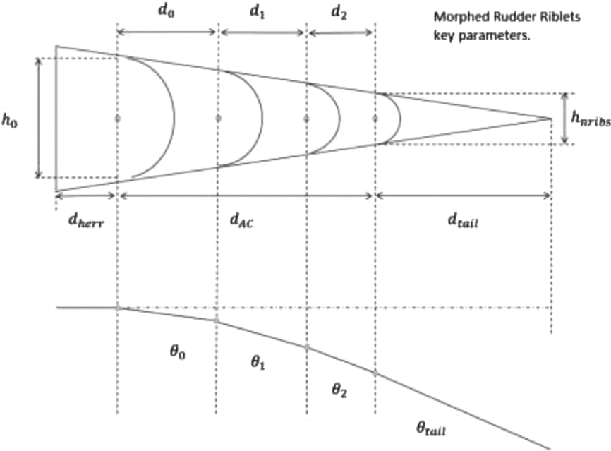
The kinematic of the morphing rudder is based on articulated ribs composed of riblets that rotate when actuated (Fig. 3). An optimisation study of the number and configuration of these riblets is performed. The configuration with more riblets results in better adaptation to the target curve shape and therefore better aerodynamic efficiency. However, this approach increases the weight. The optimum is achieved balancing these two trends. Also in this case under study due to high rudder deflections to be considered (±30°) there is non-linearity that needs to be analysed with in adequate approach and detail.
Geometry parameters for articulated ribs.

The rotation law relationship between the angle turned by one riblet and the next with respect to its initial position is defined. The law of rotation at each joint can be imposed by the limitations of the mechanism of action, but as the mechanism itself is not the focus of this study, a mathematical equation for rotation type that can then be physically feasible and functionally tested is proposed. One simple rotation equation is a geometrical one, where the angle rotated by a rib is proportional to the angle of the previous rib. The proportionality constant is k 1, and θ is the angle rotated by the riblets, with subscript i the identifier of each riblet. Figure 3 depicts the parameters involved.
 $$\begin{equation}
{\theta _{i + 1}} = {k_1}{\theta _i}
\end{equation}$$
This equation can also express the angle rotated by the riblet i depending on the angle rotated by the first rib:
 $$\begin{equation}
{\theta _i} = {\left( {{k_1}} \right)^i}{\theta _0}
\end{equation}$$
It also establishes the proportionality relationship between the length of a rib and the previous one by a geometric progression constant k 2 with di the length from the centre of the rib joint i to the centre of the rib joint i + 1.
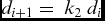 $$\begin{equation}
{d_{i + 1}} = \ {k_{2\ }}{d_i}
\end{equation}$$
 $$\begin{equation}
{d_i} = {\left( {{k_2}} \right)^i}{d_0}
\end{equation}$$
So far, four parameters that define this study target have been identified: d 0, θ0, k 1 and k 2. The number of ribs, nribs , is also added, as are the length between the rear spar and the first joint dherr , and the tail length dtail .
There are certain constraints that reduce the number of parameters. The sum of the lengths of all the riblets, the tail and the first riblet or fitting must be equal to the length of the rudder:
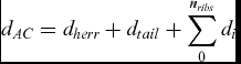 $$\begin{equation}
{d_{AC}} = {d_{herr}} + {d_{tail}} + \mathop \sum \limits_0^{{n_{ribs}}} {d_i}
\end{equation}$$
There is also a relationship between the accumulated length of the riblets and the proportionality constant using the summation of a geometric progression of the ratio k 2 and first element d 0:
 $$\begin{equation}
\mathop \sum \limits_0^{{n_{ribs}}} {d_i} = {d_0}\mathop \sum \limits_0^{{n_{ribs}}} {\left( {{k_2}} \right)^i} = {d_0}\frac{{{{\left( {{k_2}} \right)}^{{n_{ribs}}}} - 1}}{{{k_2} - 1}},
\end{equation}$$
 $$\begin{equation}
{d_{AC}} = {d_{herr}} + {d_{tail}} + {d_0}\frac{{{k_2}^{{n_{ribs}}} - 1}}{{{k_2} - 1}}\
\end{equation}$$
This means that the parameters are coupled and therefore a degree of freedom is lost.
We impose the condition that the deflecting rotation must be equivalent to 30° to obtain an additional coupling as follows:
 $$\begin{equation}
{d_{AC}}\sin 30 = {d_{herr}}\sin 0 + {d_{tail}}\sin {\theta _{tail}} + \mathop \sum \limits_0^{{n_{ribs}}} {d_i}\sin {\theta _i}
\end{equation}$$
Therefore,
 $$\begin{equation}
\frac{{{d_{AC}}}}{2} = {d_{tail}}\sin {\theta _{{n_{ribs}} + 1}} + \mathop \sum \limits_0^{{n_{ribs}}} {\left( {{k_2}} \right)^i}{d_0}\sin \left( {{{\left( {{k_1}} \right)}^i}{\theta _0}} \right)
\end{equation}$$
There is another consideration that further reduces the number of variables. The geometry of the control surface presents diminishing heights along the chord. This leads us to define a binding relation between the height and the length of each rib that can be expressed as:
 $$\begin{equation}
\frac{{{d_0}}}{{{h_0}}} = \frac{{{d_0}{k_2}}}{{{h_1}}} = \frac{{{d_0}{{\left( {{k_2}} \right)}^2}}}{{{h_2}}} \cdots = \frac{{{d_0}{{\left( {{k_2}} \right)}^{{n_{ribs}}}}}}{{{h_{{n_{ribs}}}}}}
\end{equation}$$
Calling the tail half-angle α:
 $$\begin{equation}
{h_0} = h - {d_{herr}}\sin \alpha ,
\end{equation}$$
 $$\begin{equation}
{h_{{n_{ribs}}}} = {d_{tail}}\sin \alpha ,
\end{equation}$$
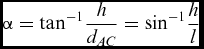 $$\begin{equation}
\alpha = {\tan ^{ - 1}}\frac{h}{{{d_{AC}}}} = {\sin ^{ - 1}}\frac{h}{l}
\end{equation}$$
Therefore,
 $$\begin{equation}
\frac{{{h_{{n_{ribs}}}}}}{{{h_0}}} = \frac{{{d_{tail}}\sin \alpha }}{{h - {d_{herr}}\sin \alpha }} = {\left( {{k_2}} \right)^{{n_{ribs}}}}
\end{equation}$$
This gives us the law of proportionality for the homothetic riblets once the number of ribs is selected. Introducing this into the above equation results in d 0. To avoid complexities in the mechanism and avoid penalising the weight, the process is started with three ribs which are added to the tail, so the fitting involves four joints. The values of the parameters obtained to define the geometry of the first articulated rib are shown below, with the angle values in radians and the distances in meters. The results are included in Table 2.
Articulated ribs results

2.2 Skins span-wise
Skins are cell-based skeletons that span-wise present higher stiffness than chord-wise.
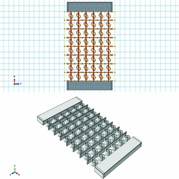
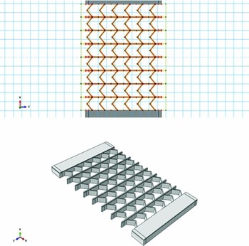
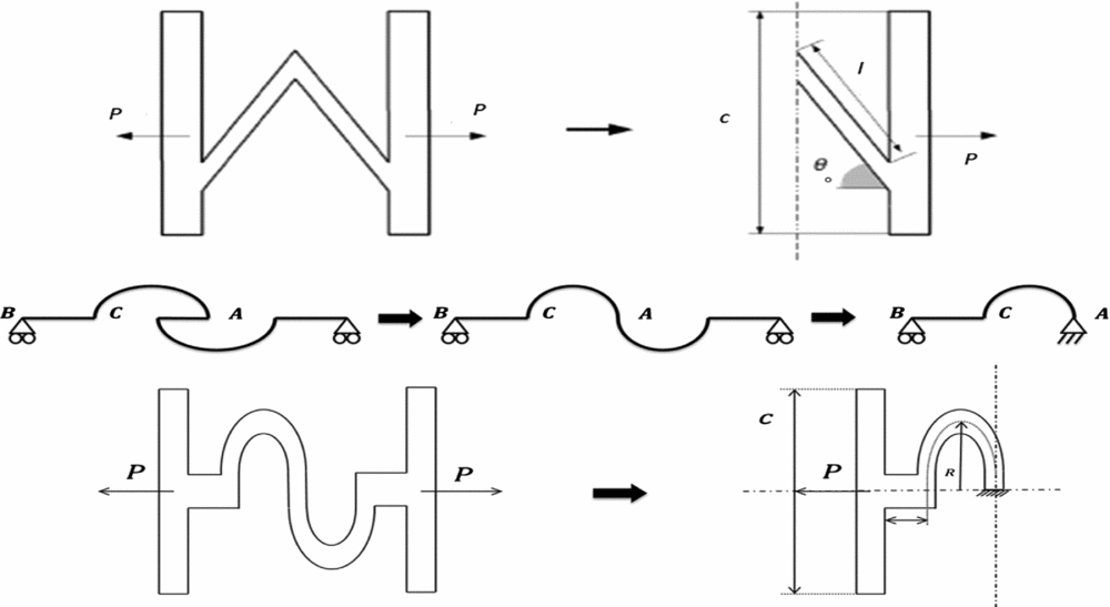
Two different geometric configurations seeking to maximise the elastic module E 1, E 2, E 3 with minimum weight are considered. The chord-wise direction corresponds to the X axis or Direction 1 in these studies; the Y axis corresponds to the thickness (Direction 2) and the Z axis to span-wise direction (Direction 3). The two configurations are a novel ‘double C’ Fig. 4 and ‘V straight’ (Fig. 5). The latter can be found in the literature(Reference Bubert15) and it is composed of two straight segments that form a given angle within the parameter for orthotropic characterisation with the stiffeners. The new double C is composed of two connected curved segments. The radius of these curved members is the parameter for defining the orthotropic behaviour of the panel, as is the presence of a connecting straight segment between the curved members and the length. We analyse whether this novel double-C configuration, keeping the basic common geometric features, shows improvements in terms of specific elastic modulus in relation to the V-straight configuration.
double-C skeleton- skin panels.

V-plane skeleton-skin panels.

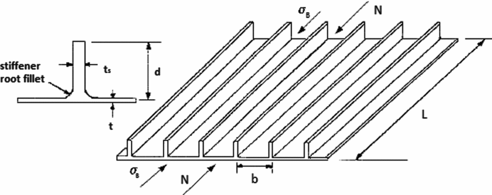
The skins sizing critical span-wise condition is compression load. For the compressed skin, the critical failure mode is buckling due to the axial force caused by rudder bending in combination with the rudder torsion shear flow. For the tension failure mode, we derive the skin's maximum combined von Mises stresses and compare them with rupture allowable ones. The skins are modelled as constituted by single-ply orthotropic material; therefore, due to the grid-cell skeleton configuration of the skins, it is necessary to determine the equivalent material properties. The geometric parameters involved in the skins' strength analysis are t (basic cell thickness), ts (stringer web thickness), b (distance between adjacent stringers) and stringers height d (Fig. 6)).
Reinforced skin geometry parameters.
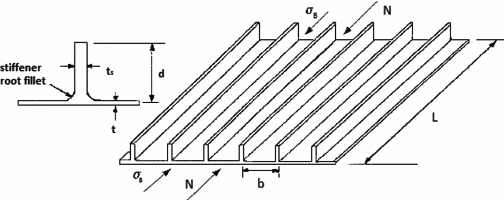
The second group of parameters for skins is related to the configuration of the skeleton itself. The skeleton is not rigid chord-wise but presents a span-wise stiffness due to the various stringers. We derive a number of parameters on which the effective stiffness of the skeleton depends. Different close-to-zero Poison panels configurations based on two cell geometric parameters and topology alternatives have been pre-selected to search for the lower weight configuration and at the same time fulfil strength and stiffness requirements.
The allowable load flows on the rudder skins to perform the compression strength analysis have been obtained by means of the Farrar theory(Reference Farrar16) programmed into MATLAB. This code takes as input the internal compression loads and the geometry constraints and performs calculations that yield an optimum set of geometrical parameters for the structure.
Farrar's theory states that the optimum structure is one in which the compression stresses at the beginning of the initial local buckling σ B match the corresponding Euler buckling as a column σ E . In this way, when the local buckling is induced, the global buckling of the entire skin starts. These stresses are given by these equations:
 $$\begin{equation}
{\sigma _B} = \frac{{{\sigma _B}}}{{{\sigma _0}}}{f_1}\left( {\frac{{{A_S}}}{{bt}},\frac{{{t_S}}}{t}} \right)3.6\ E\ {\left( {\frac{t}{b}} \right)^2},
\end{equation}$$
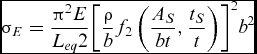 $$\begin{equation}
{\sigma _E} = \frac{{{\pi ^2}E}}{{{L_{eq}}2}}{\left[ {\frac{\rho }{b}{f_2}\left( {\frac{{{A_S}}}{{bt}},\frac{{{t_S}}}{t}} \right)} \right]^2}{b^2}
\end{equation}$$
The parameters involved are represented on Fig. 6:
-
• As is the area of the rectangular section of stringers.
(19)
$$\begin{equation}{A_s} = d \times {t_s}\end{equation}$$
-
• Leq is the equivalent length of the skins and stringers, since it is assumed that ribs provide a stable support it is the pitch between ribs.
-
• Erev is the modulus equivalent for a one-ply material
-
• σ0 is the skin buckling as a plate
(20)
$$\begin{equation}{\sigma _0} = 3.6E{\left( {\frac{t}{b}} \right)^2}\end{equation}$$

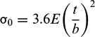
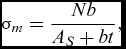
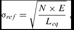
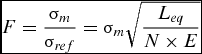
The Farrar theory also defines a reference stress σ ref and a mean stress σ m because the reinforced skin stress distribution is not uniform. The Farrar factor, F, is defined as the ratio between the mean and reference stresses, concluding that the higher the value of F, the most optimum the structure results. The expressions are:
 $$\begin{equation}
{\sigma _m} = \frac{{Nb}}{{{A_S} + bt}},
\end{equation}$$
 $$\begin{equation}
{\sigma _{ref}} = \sqrt {\frac{{N \times E}}{{{L_{eq}}}}} \ ,
\end{equation}$$
 $$\begin{equation}
F = \frac{{{\sigma _m}}}{{{\sigma _{ref}}}} = {\sigma _m}\sqrt {\frac{{{L_{eq}}}}{{N \times E}}} \
\end{equation}$$
If we now imposed the condition of simultaneous local and global buckling, and both are equal to average stress: σ m = σ B = σ E , then F is obtained as a solely function on the geometry parameters, specifically the parameters ts , t, b and d.
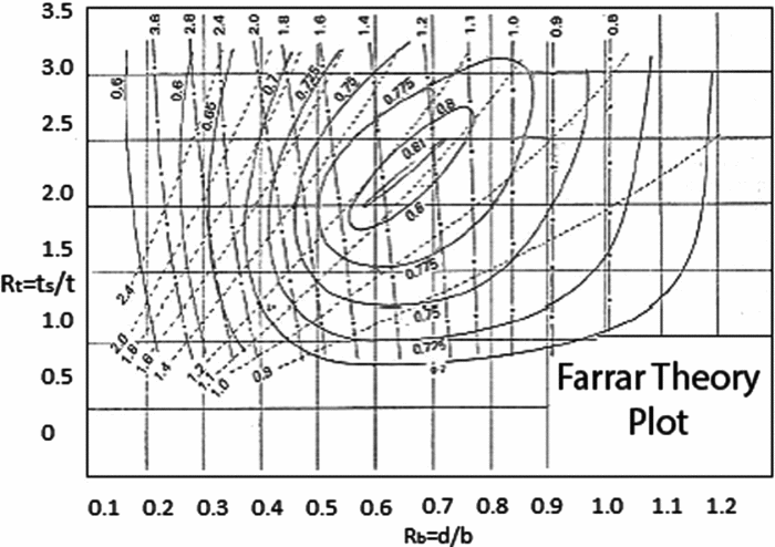
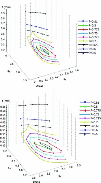
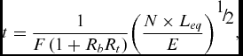
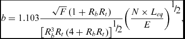
The problem of applying this theory to a real case is the combination between equations and graphs. In this study, the graphs for each Farrar factor F level have been MATLAB-modelled. Figures 7 and 8 show original Farrar plots and the MATLAB plots. So, starting with known values of Rb = d/b and Rt = t/ts and the graph F = f (Rb , Rt ), the values of all the other geometric parameters as functions of Leq and the Young modulus E have been derived, averaging between the stringers and the skin:
Original Farrar theory plot.(Reference Farrar16)

Farrar theory plot and MATLAB results for two different lengths.

 $$\begin{equation}
t = \frac{1}{{F\left( {1 + {R_b}{R_t}} \right)}}{\left( {\frac{{N \times {L_{eq}}}}{E}} \right)^{{\raise0.7ex\hbox{$1$} \!
/ \!\lower0.7ex\hbox{$2$}}}},
\end{equation}$$
 $$\begin{equation}
b = 1.103\frac{{\sqrt F \left( {1 + {R_b}{R_t}} \right)}}{{{{\left[ {R_b^3{R_t}\left( {4 + {R_b}{R_t}} \right)} \right]}^{{\raise0.7ex\hbox{$1$} \!
/ \!\lower0.7ex\hbox{$2$}}}}}}{\left( {\frac{{N \times {L_{eq}}}}{E}} \right)^{{\raise0.7ex\hbox{$1$} \!
/ \!\lower0.7ex\hbox{$2$}}}},
\end{equation}$$
 $$\begin{equation}
{F^4} = \frac{{\sigma _m^4}}{{\frac{{N \times E}}{{{L_{eq}}}}}} = \frac{{\sigma _m^2{\sigma _B}{\sigma _E}}}{{\frac{{N \times E}}{{{L_{eq}}}}}} = \ldots = \frac{{{\sigma _B}}}{{{\sigma _0}}}\left( {\frac{{{A_S}}}{{bt}},\frac{{{t_S}}}{t}} \right)3.6{\pi ^2}{\left( {\left[ {\frac{\rho }{b}\left( {\frac{{{A_S}}}{{bt}},\frac{{{t_S}}}{t}} \right)} \right]} \right)^2}\frac{1}{{\left( {\frac{{{A_S}}}{{bt}} + 1} \right)}}
\end{equation}$$
The skin results are included in Table 3. These results correspond to the optimum minimum weight and geometry of an equivalent single-layer panel.
Skins results

2.3 Chord-wise skins
The chord-wise skin can deform as a skeleton up to certain level to accommodate the morphing. To characterise the strength, the maximum stress at break under tension loading is considered, and for the stiffness, just the tensile stiffness. This simplifies the skeleton characterisation to only two equations.
An equivalent material of constant thickness is considered(Reference Vos17) to obtain the properties of the cell-based skeleton. The skeleton is a three-direction orthotropic structure. In- plane mechanical properties are determined by 5 parameters: E 1, E 2, G 12, v 12 and v 21 and out of plane by other 7: E 3, G 13, G (23,) v 13, v 31, v 23 and v 32.
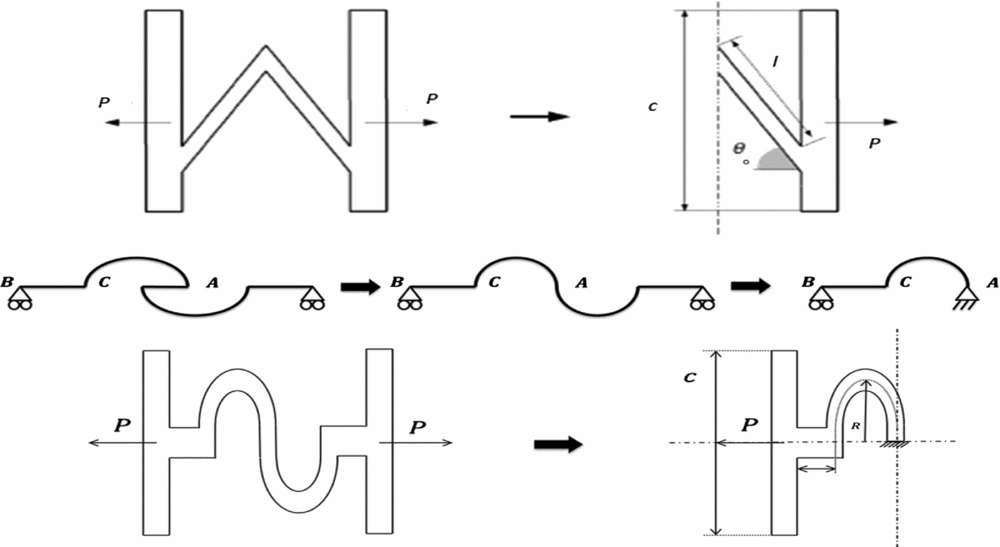
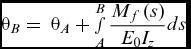
To calculate the elastic module of the new double-C configuration, a number of assumptions have been considered. The Euler-Bernoulli theory should be applicable. This means that the deformations are sufficiently small so that the sections originally perpendicular to the line of deformation remain perpendicular after deformation. There is also a relationship between the span-wise thickness of the stringers obtained in the previous section and the chord-wise thickness of the springs: tm = ks × ts . Also, this thickness is much smaller than the characteristic length of the spring tm /Lm ≪ 1. Using symmetry conditions, the analysis is simplified by imposing the appropriate boundary conditions in each case, so the point on the axis of symmetry will be called A and the one located in the stringer will be called B. The following equations that provide the values of the linear displacements at point B (uB , vB ) and the rotation angle θ B as a function of these values on point A are applied in Fig. 9.
V-straight and double-C parameters.
 $$\begin{equation}
{u_B} = \ {u_A} + {\theta _A}\left( {{y_B} - {y_A}} \right) - \mathop \smallint \limits_A^B \frac{{{M_f}\left( s \right)}}{{{E_0}{I_z}}}\left( {{y_B} - y} \right)ds,
\end{equation}$$
 $$\begin{equation}
{v_B} = \ {v_A} + {\theta _A}\left( {{x_B} - {x_A}} \right) - \mathop \smallint \limits_A^B \frac{{{M_f}\left( s \right)}}{{{E_0}{I_z}}}\left( {{x_B} - x} \right)ds,
\end{equation}$$
 $$\begin{equation}
{\theta _B} = \ {\theta _A} + \mathop \smallint \limits_A^B \frac{{{M_f}\left( s \right)}}{{{E_0}{I_z}}}ds
\end{equation}$$
Based on the above equations, the value of the elastic module E 1 is obtained. To do so, we previously derived the value of the displacement at point B by imposing the equations of static equilibrium under a concentrated force P. We are then required to take advantage of the boundary conditions to determine the value of hyperstatic variables:
 $$\begin{equation}
{u_A} = 0,
\end{equation}$$
 $$\begin{equation}
{v_A} = 0,
\end{equation}$$
 $$\begin{equation}
{v_B} = 0,
\end{equation}$$
 $$\begin{equation}
{\theta _B} = 0,
\end{equation}$$
 $$\begin{equation}
{H_A} + P = 0,
\end{equation}$$
 $$\begin{equation}
{V_A} + {V_B} = 0,
\end{equation}$$
 $$\begin{equation}
{M_B} + \ {V_A}\left( {2R + l} \right) = 0,
\end{equation}$$
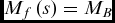
Then the hyperstatic unknown MB is selected. The bending moment, which is then introduced into the above equations, is defined within two sectors: from A to C and from C to B.
For A to C: s (0 , l)
 $$\begin{equation}
{M_f}\left( s \right) = {M_B}
\end{equation}$$
For C to B: γ (0 , 2π)
 $$\begin{equation}
{M_f}\left( {{\rm{\ }}\gamma } \right) = {M_B} + PR\sin {\rm{\ }}\gamma
\end{equation}$$
The system is solved, first expressing θ A as a function of MB and rest of parameters of the problem: E, I, l, R and P.
 $$\begin{equation}
{\theta _A}EI = {M_B}\left( {l + 2R} \right) + 2P{R^2},
\end{equation}$$
 $$\begin{equation}
{\theta _B}EI = {\theta _A}EI - \mathop \smallint \limits_0^{l + 2R} {\rm{\ }}{M_B}ds - \mathop \smallint \limits_0^\pi {\rm{\ }}P{R^2}\sin \gamma d\gamma = 0,
\end{equation}$$
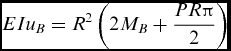
Then uB is derived as a function of MB after imposing two conditions:
 $$\begin{equation}
{u_A} = 0,
\end{equation}$$
 $$\begin{equation}
{y_A} = {y_B},
\end{equation}$$
 $$\begin{equation}
\hbox{\it EIu}{_B} = \ \mathop \smallint \limits_0^\pi \left( {{M_B} + PR\sin \gamma } \right){R^2}\sin \gamma d\gamma ,
\end{equation}$$
 $$\begin{equation}
EI{u_B} = {R^2}\left( {2{M_B} + \frac{{PR\pi }}{2}} \right)
\end{equation}$$
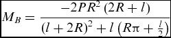
To solve the problem, it is necessary to calculate the value of MB . For this, it is assumed:
 $$\begin{equation}
{v_A} = {v_B} = 0,
\end{equation}$$
 $$\begin{equation}
{x_A} = 2R + l,
\end{equation}$$
 $$\begin{equation}
{x_B} = 0,
\end{equation}$$
 $$\begin{equation}- EI{\theta _A}\left( {2R + l} \right) - \mathop \smallint \limits_0^l {M_B}sds - \mathop \smallint \limits_0^\pi {M_B}\left( {R\cos \gamma + l} \right)Rd\gamma - \mathop \smallint \limits_0^\pi P{R^3}\sin \gamma \cos \gamma d\gamma = 0
\end{equation}$$
That yields:
 $$\begin{equation}
{M_B} = \frac{{ - 2P{R^2}\left( {2R + l} \right)}}{{{{\left( {l + 2R} \right)}^2} + l\left( {R\pi + \frac{l}{2}} \right)}}
\end{equation}$$
Then:
 $$\begin{equation}
{u_B} = \frac{{{R^2}}}{{EI}}\left( {\frac{{ - 4P{R^2}\left( {2R + l} \right)}}{{{{\left( {l + 2R} \right)}^2} + l\left( {R\pi + \frac{l}{2}} \right)}} + \frac{{PR\pi }}{2}} \right)\
\end{equation}$$
Therefore,
 $$\begin{equation}
{\varepsilon _B} = \frac{{{R^2}}}{{EI\left( {2R + l} \right)}}\left[ {\frac{{ - 4P{R^2}\left( {2R + l} \right)}}{{{{\left( {l + 2R} \right)}^2} + l\left( {R\pi + \frac{l}{2}} \right)}} + \frac{{PR\pi }}{2}} \right]
\end{equation}$$
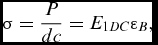
Since
 $$\begin{equation}
\sigma = \frac{P}{{dc}} = {E_{1DC}}{\varepsilon _B},
\end{equation}$$
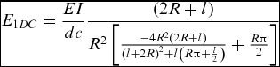
where d is the height of the stringers and c is a new parameter that defines the distance between springs. Thus,
 $$\begin{equation}
{E_{1DC}} = \frac{{EI}}{{dc}}\frac{{\left( {2R + l} \right)}}{{{R^2}\left[ {\frac{{ - 4{R^2}\left( {2R + l} \right)}}{{{{\left( {l + 2R} \right)}^2} + l\left( {R\pi + \frac{l}{2}} \right)}} + \frac{{R\pi }}{2}} \right]}}
\end{equation}$$
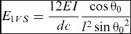
We apply this method to the case of the V-straight configuration, whose geometry can be seen in Fig. 9:
 $$\begin{equation}
{E_{1VS}} = \frac{{12EI}}{{dc}}\frac{{\cos {\theta _0}}}{{{l^2}\sin {\theta _0}^2}}
\end{equation}$$
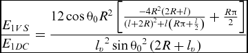
The division of these two last expressions yields this comparison ratio:
 $$\begin{equation}
\frac{{{E_{1VS}}}}{{{E_{1DC}}}} = \frac{{12\cos {\theta _0}{R^2}\left[ {\frac{{ - 4{R^2}\left( {2R + l} \right)}}{{{{\left( {l + 2R} \right)}^2} + l\left( {R\pi + \frac{l}{2}} \right)}} + \frac{{R\pi }}{2}} \right]}}{{{l_v}^2\sin {\theta _0}^2\left( {2R + {l_v}} \right)}}
\end{equation}$$
Then, after an approximation method, the conclusion is as follows:
 $$\begin{equation}
\frac{{{E_{1VS}}}}{{{E_{1DC}}}} \approx \frac{1}{9}
\end{equation}$$
It is clear that the double-C configuration is one order of magnitude stiffer chord-wise than the V-straight configuration.
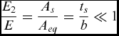
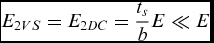
The elastic modulus value E 2 is almost the same for both configurations since it depends only on the number of stringers, which in turn depends on the chord length and a shape that can be considered equal in both cases. Consequently, the relationship between module E 2 and the equivalent material is proportional to the area ratio:
 $$\begin{equation}
\frac{{{E_2}}}{E} = \frac{{{A_s}}}{{{A_{eq}}}} = \frac{{{t_s}}}{b} \ll 1
\end{equation}$$
In consequence:
 $$\begin{equation}
{E_{2VS}} = {E_{2DC}} = \frac{{{t_s}}}{b}E \ll E
\end{equation}$$
Similarly to E 2, the elastic modulus E 3 is proportional to the area, and thus considerably smaller than the case of the skeleton compared to the modulus of the material itself. In the case of the double-C configuration, the equivalent area can be calculated as the sum of the different zones, the stringers, the two straight sections and the two areas in C:
 $$\begin{equation}
{A_{eq}} = 1.15{t_s}\left( {c + {k_s}\left( {2l + 2\pi R} \right)} \right)
\end{equation}$$
where ks represents the ratio between the span-wise stringer thickness divided by the springs' chord-wise thickness. Moreover, it is multiplied by a factor of 1.15 to take into account the part of the two ‘C’ shapes that have been previously neglected. The area ratio is as follows.
 $$\begin{equation}
\frac{{{E_3}}}{E} = \frac{{{A_{eq}}}}{{{A_s}}} = \frac{{1.15{t_s}\left( {c + k\left( {2l + 2\pi R} \right)} \right)}}{{cb}}
\end{equation}$$
In this equation, the numerator is approximately proportional to ts (c + b) and about the same order as c and b. Therefore E 3 and E 2 are of the same order.
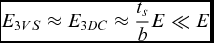 $$\begin{equation}
{E_{3VS}} \approx {E_{3DC}} \approx \frac{{{t_s}}}{b}E \ll E
\end{equation}$$
All the terms to define the geometry related to the equivalent springs of the two configurations have been derived.
The final calculations of the springs' mechanical characteristics, minimising the modulus E 1 and maximising the two others E 2, E 3, are now performed. These are based on the following additional considerations:
-
• The number of springs in the direction of the span is the distance between ribs divided between the parameter c, rounded.
-
• The width of the spring chord-wise is equal to b. This restricts the value of other parameters.
-
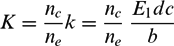
• The definition of K, as the stiffness associated with the springs, is performed. The calculation of the individual stiffness of each spring as the product of the modulus of rigidity E 1 multiplied by the height of the stringers d and the width of each spring c and divided by the length of each spring b is finally obtained. Then, associating the springs in parallel and in series depending on the number of springs in the direction of the chord nc and span-wise ne results in:
(62)
$$\begin{equation}K = \frac{{{n_c}}}{{{n_e}}}k = \frac{{{n_c}}}{{{n_e}}}\ \frac{{{E_1}dc}}{b}\end{equation}$$
From the standpoint of structural integrity, a geometry that makes the maximum tension stress σ as small as possible to avoid rupture, as well as lower average compression stress to avoid local or global buckling, is the goal of this part of the analysis. Tables 4 and 5 present the final values for the two configurations under study.
V-straight configuration, springs parameters

Double-C configuration, springs parameters

3.0 RESULTS AND DISCUSSION
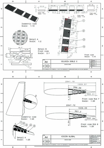
The structural feasibility of this design is verified by integrating the morphing skin structure in solid CATIA 5 models for cinematic mechanical analysis and simulation. Figure 10 shows some of the geometrical details of these 3D models.
Double-C geometrical definition.

The study is completed with numerical models based on the finite element method code Abaqus, taking into account the obtained geometrical parameters, the boundary conditions and the applied loads. The utilisation of Abaqus for solving similar problems is well documented in the literature. The renewable energy wind industry provides examples for studying morphing in wing blades with Abaqus models(Reference Lachenal, Daynes and Weaver7,Reference Daynes and Weaver9,Reference Chen, Wang, Shen, Pang, Li and Guo18) . Recently, Abaqus models of human tissues that morph to different shapes have been developed(Reference Wang, Gao, Luo, Berry, Griffith, Ogden and Wang19). The complexity of combining large deformations, composite materials and novel actuation systems has also been recently studied with help of Abaqus models(Reference Portela, Camanho, Weaver and Bond4,Reference Diaconu, Weaver and Mattioni20) .
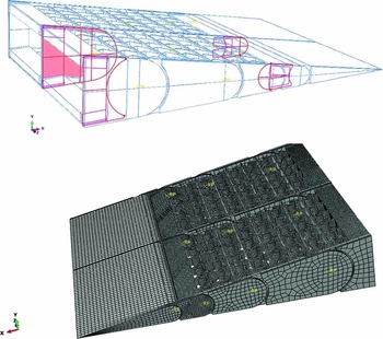
Abaqus FEM models with rough meshing but enough detail to test the two types of skeletons excluding the exterior elastomeric skin have been constructed. Then the mesh is refined to test the full skin for the two configurations. The model has been made for three consecutive ribs, so the simulation results in the central rib are as representative as possible of the typical loads that most rudder ribs withstand. The geometry of the second rib is considered because, as shown before, it has the highest internal loads. This model is cylindrical and does not consider the variation of the chord along the span. This simplification is proven in industrial practice and the results correlated with tests are good for a detailed analysis around a rib (Fig. 11).
Abaqus FEM 2.5D rudder model.

The applied loads to the models correspond to the previously indicated of one engine out condition with additional enforced displacements due to a 30° rudder rotation.
3.1 V-straight configuration results
Figure 12 shows the Von Mises stress on a scale between 8 KPa and 3.6 MPa (material elastic limit). This scale will be maintained for the rest of the stress results. As is shown, there are areas of particular stress concentration, particularly in the junction zones between the stringers and the chord ‘springs’. The most critical areas are the joint of the skeleton with the trailing edge continuous spar, and the first fitting rib clamping area. This is due to the transmitted enforced displacements through the articulated ribs to the skeleton and the stiff trailing-edge member. This result is repeated in all cases. This feature is solved with adequate reinforcements.
V-straight FEM von Mises stress (N/m2).

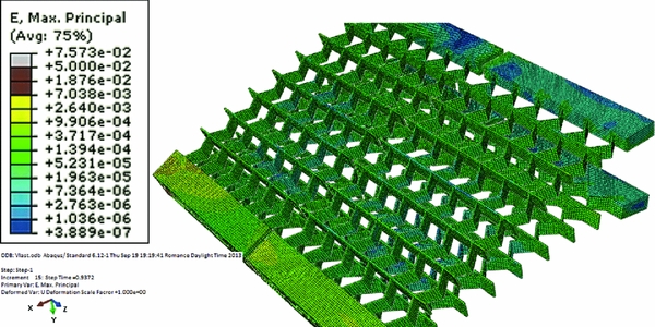
The maximum deformations are on the order of 5% (Fig. 13); this scale will remain constant for the rest of the strain plots.
V-straight FEM strains (µε).
3.2 Double-C configuration results
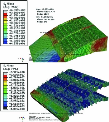
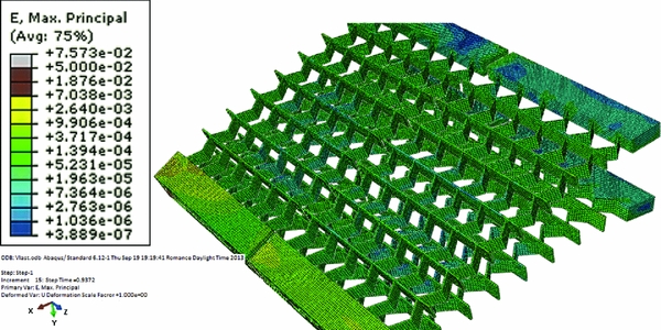
The results for this configuration are included in Fig. 14. The behaviour is similar to the ‘V’ configuration, with greater differences in the chord spring stresses and strains. A 90% reduction of maximum von Mises stress in relation to the V-straight configuration is derived.
Double-C FEM von Mises stress (N/m2).

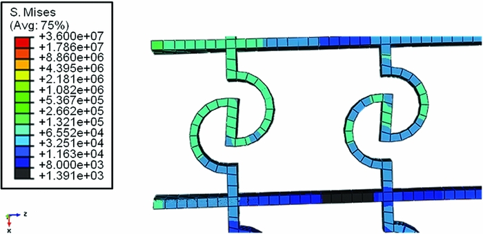
Looking more closely at one of the springs (Fig. 15), the rotation is clearly observed in the central area. This is the angle θ A formed by the line that connects the two C shapes with the chord-wise axis. This rotation is in the order of the angle between the local plane normal with the vertical.
Double-C FEM spring rotation detail, von Mises stress (N/m2).
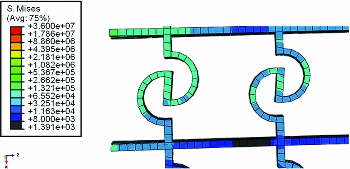
It is relevant to note that these stresses are much less concentrated than in the previous configuration. This is critical from the point of view of the durability of the structure and compensates for its greater stiffness. These concentrations need to be further studied from a fatigue point of view. Complete fatigue studies from a multi-disciplinary approach is important in aircraft design with novel morphing devices(Reference Kota, Hetrick and Osborn21,Reference Vasista, Tong and Wong22) specially with thermo-mechanical coupling(Reference Jee23) and the effect of chemical resistance(Reference Thill, Etches, Bond, Potter and Weaver24). Figure 16 includes the skeletons strains.
Double-C FEM strains (µε).

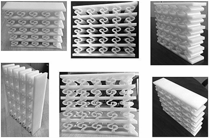
A double-C representative panel has been produced by an additive layer manufacturing process using the selected material VisiJet M 3X. Figure 17 includes some pictures of the manufactured specimen.
Pictures of 3D printed element.
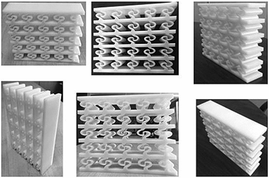
The 3D printer is a ProJet 7000 MP based on stereolithography technology. The amount of material used is 210 g. The time consumed is around 7 hours.
4.0 CONCLUSIONS
This study includes the development of an analytical model to design an adaptable skin with multiple parameters, constraints and configurations. The equations that relate morphing skin 3D printable skeleton mechanical properties with actual zero Poisson cellular panels’ geometry and material have been obtained. Based on the obtained values, it is concluded that the design is functionally feasible and structurally compliant for aircraft structures applications from static strength point of view. In particular, this study presents some remarks:
-
• The so called double-C configuration has been proved to improve the V-straight configuration in relation to the rudder functional requirements.
-
• The selection of materials is critical to achieve a structurally compliant solution.
-
• The resultant skin skeleton elastic modules have to be large enough to withstand the internal loads but not so big that the required actuators forces are beyond current available commercial servomotor during the deformation process.
Further studies are required to search for more adequate 3D printable materials to be processed by additive layer manufacturing means or similar. In particular, the characterisation of fatigue life and the effect of relevant environment are pending for future work, as well as a study of the highly deformable material and its integration to the skins for non-permeability purposes.
The current commercially available 3D printing machines present a limit to critical dimensions, in particular the size of the panels, being the maximum size currently available around 0.5 m. The current available resolutions of the 3D printable elements are not affecting the geometrical definition of the highly orthotropic panels, but when more miniaturisation of the design is required, this resolution could be a limiting factor on the design. This potential issue might be further studied in the future at similar miniature 3D printed elements.