I. INTRODUCTION
Supercapacitors (SCs) are promising high performance energy storage systems due to their relatively fast rate of energy storage and delivery. Their high power density and excellent cycling lifetime metrics make SCs suitable for a wide variety of applications including portable electronics, electric or hybrid electric vehicles, and alternative energy resources.Reference Simon and Gogotsi1, Reference Wu, Ren, Wang, Li, Liu and Cheng2 Typically, there are two types of SCs. The first type is called electrochemical double-layer capacitor (EDLC), which is based on ion adsorption. The second type is the pseudocapacitor, which operates on the principle of fast surface redox reactions.Reference Simon and Gogotsi1, Reference Hu, Choi, Yang, Jeong, La Mantia, Cui and Cui3–Reference Stoller and Ruoff6 The excellent chemical and physical properties of carbon materials such as high conductivity, large surface area, excellent corrosion resistance, and temperature stability, and their relatively low cost, make them valuable candidates for the electrodes of EDLCs.Reference Stoller and Ruoff6, Reference Pandolfo and Hollenkamp7 To enhance the performance of SCs based on carbon materials, intensive research has been conducted including different types of carbon nanostructures, including carbon capsules, carbon nanotubes/nanofibers (CNTs/CNFs), and graphene.Reference Hu, Choi, Yang, Jeong, La Mantia, Cui and Cui3, Reference Yu, Roes, Davies and Chen8–Reference Wang, Guo, Penchev, Ruiz, Bozhilov, Yan, Ozkan and Ozkan13 Although carbonaceous nanostructures indicate a relatively high gravitational specific capacitance (normally >50 F/g), the areal capacitances are always very low and falling into the range of mF/cm2 or even μF/cm2.Reference Frackowiak14–Reference Weng, Su, Wang, Li, Du and Cheng16 The relatively low areal capacitance value is due to the relatively low mass loading of the active material, which is dependent on the processing methods.
In this work, we report the growth of a novel three-dimensional (3D) chrysanthemum-like carbon nanofiber (CCNF) architecture on highly porous nickel foams by ambient pressure chemical vapor deposition (APCVD). The as-grown nanocarbon foam architectures are utilized as the electrodes of SCs, and electrochemical measurements indicate that the new type of nanocarbon electrodes provides very large areal specific capacitance and excellent electrochemical stability, which suggest their future applications for energy storage devices.
II. EXPERIMENTAL
A. Growth of CCNF foam architectures
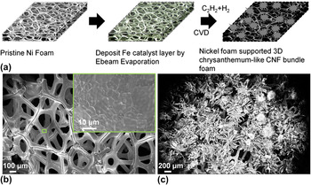
The CCNF foam architectures were synthesized via APCVD on a regular 1-mm-thick nickel foam, which is widely used in the battery industry as a current collector. A schematic illustration of the synthesis procedure for CCNF architectures is shown in Fig. 1(a). First, after the cleaning of pristine nickel foam [Fig. 1(b)] with diluted acetic acid and washing with deionized water, a 5-nm-thick layer of Fe catalyst nanoparticles is deposited on the nickel foam via electron beam evaporation (Temescal, BJD-1800, Livermore, CA). Second, a reactive ion etching O2 plasma treatment (50 sccm O2, power 250 W) is applied to the Fe-coated nickel foam to form an oxide layer on the foam frame surface and also oxidize the iron catalyst. Followed by a plasma treatment, the pretreated nickel foams were loaded into a quartz tube furnace chamber, heated to 700 °C under ambient pressure in an Ar/H2 (200:200 sccm ratio) atmosphere, and annealed for 10 min. For the growth of chrysanthemum-like carbon nanostructures, acetylene (50 sccm) is introduced into the chamber under ambient pressure for 20 min, and the chamber temperature was then reduced to room temperature under inert gas flow [Fig. 1(c)].
(a) Schematic illustration of the growth process of the 3D CCNF bundle foam. SEM image of (b) represents the pristine nickel foam structure. Inset shows the high magnification morphology of the pristine nickel foam and (c) shows the as-grown 3D CCNF bundle foam structure.

B. Materials characterization
Surface structure and morphology of the nanocarbon foam architectures and pristine nickel foam films are investigated using optical microscopy and scanning electron microscopy (SEM; Leo-Supra, 1550) with a field emission source. Transmission electron microscopy (TEM; Philips, CM300) is used to characterize the nanocarbon structures in detail such as the wire nature of the grown carbon nanofibers (CNFs).
C. Fabrication of SC cells and electrochemical measurements
The CCNF architectures are sectioned with equal areas and soaked with an electrolyte (6 M KOH aqueous). A two-electrode measurement technique was used for the electrochemical measurements, where the two pretreated electrodes were assembled into a sandwich structure with a porous separator (Celgard 3501, Charlotte, NC) placed in between them. The packaging of the SC cell was conducted at room temperature. The packaged SC is connected to an electrochemical analyzer (Gamry, Reference 600™, Warminster, PA) with an alligator clip. Cyclic voltammetry (CV), chronopotentiometry (CD; for charge–discharge measurements), and electrochemical impedance spectroscopy (EIS) are conducted to evaluate the performance of the SCs. CV scans are performed in the range 0–1 V at scan rates ranging from 2.5 to 1000 mV/s. The charge–discharge measurements are conducted at different current densities, and the stability test is obtained at a charge–discharge current density of 21.33 mA/cm2. Potentiostatic EIS measurements were performed between 0.1 Hz and 1 MHz with an amplitude of 10 mV.
III. RESULTS AND DISCUSSION
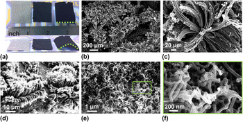
Topside view optical micrographs of inch-scale pristine nickel foam and as-grown CCNF foam architectures with two different loading amounts are shown in Fig. 2(a) (left—pristine nickel foam, middle—lightly loaded CCNF, right—heavily loaded CCNF). The loading amount of the carbon nanostructure can be controlled with various growth times, catalyst amounts, and carbon source concentration. Here, we controlled the loading amount primarily by changing the growth time. A sample grown for 20 min demonstrates a very high active material mass loading of 28.78 mg/cm2 [Fig. 2(a), right]. It is important to note that the loading mass in this work is the weight change of the sample measured before and after APCVD growth.
(a) Optical micrograph (top view) of inch-scale pristine nickel foam (thickness: 1.0 mm), CCNF bundle foam with mild loading, and CCNF bundle foam with heavy loading. Optical micrograph (45°/side view) shows the thickness of the foam structure and also the bending of the CNF bundle foam due to the heavy loading. SEM images in (b)–(f) represent the surface morphology of the CCNF bundle foam under different magnifications. (b) represents the densely packed CCNF grown on nickel foam frame. High magnification SEM micrograph of (c) shows the brush-like CNF bundle and (d) represents the shorter time (3 min) growth. SEM micrographs of (e) and (f) show the top view of the 3-min growth of the 3D CCNF bundle foam nanostructure.

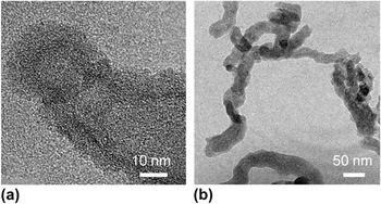
SEM imaging is used to investigate the morphology of the nanocarbon foam architectures. Images in Figs. 2(b) and 2(c) indicate the morphology of the nanostructures at different magnification. Randomly oriented, densely packed, and chrysanthemum-like nanocarbon structures are grown on the nickel foam [Figs. 2(b) and 2(c)]. By varying the growth time, the petal size and loading mass of the chrysanthemum-like nanocarbons can be controlled at the micrometer scale and in the 0.5–30 mg/cm2 range, respectively [Figs. 2(b)–2(d)]. Each chrysanthemum petal consists of a bundle of wire-like graphitic nanostructures, which were further confirmed to be CNFs by high-resolution TEM imaging. Figure 2(d) shows a sample with smaller loading of chrysanthemum-like nanocarbons compared to Figs. 2(b) and 2(c). Unlike the heavily loaded nanocarbon structure almost filling the entire nickel foam, the lightly loaded sample has not grown long enough and shows only a good coverage of the nickel frame structure. Moreover, the CNF bundles grow vertically in the beginning of the growth step and then follow a curved morphology due to larger nanocarbon loading. Figures 2(e) and 2(f) show the tip region of the chrysanthemum petal, and each petal of the chrysanthemum structure is composed of a bundle of CNFs with a diameter around 50 nm as shown in Figs. 3(e) and 3(f). Figure S1 shows the typical x-ray diffraction pattern of the as-grown CCNF foam architecture. The broad (002) diffraction peak detected at 2θ between 20° and 30° confirms the graphic nature of the CNF, which is further verified by a Raman spectra with D band centered around 1352 cm−1 and G band centered around 1592 cm−1 (Fig. S2).Reference Chinthaginjala, Thakur, Seshan and Lefferts17, Reference Yan, Tai, Chen and Xue18 We believe the formation mechanism of the 3D chrysanthemum-like morphology of the CNF bundles might be due to the combination of two possibilities: (i) the special 3D morphological nature of the nickel foam backbone and (ii) Fe–Ni alloying during the plasma treatment process.Reference Talapatra, Kar, Pal, Vajtai, Ci, Victor, Shaijumon, Kaur, Nalamasu and Ajayan19 The dense and hierarchical CNF bundle network structure possesses a large surface area that is desirable for SC electrodes. The nickel foam frame functions as a current collector for the EDLC, as a backbone for the growth of chrysanthemum-like nanocarbons, and also functions to protect the active materials loaded within the framework. TEM imaging is conducted to confirm that the wire-like graphitic nanostructures are CNFs rather than CNTs [Figs. 3(a) and 3(b)].
(a) TEM micrographs of (a) small size and (b) large size CNFs confirm the chrysanthemum-like graphitic CNF bundle foam structure and suggest that the CVD process yields CNFs rather than CNTs.

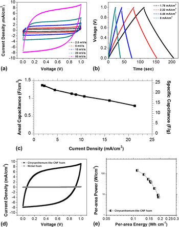
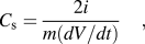
SCs based on chrysanthemum-like nanocarbon foam electrodes are fabricated with two equal areas of nanocarbon foam electrodes spaced using a porous separator. CV measurements are performed in the range of 0–1 V with sweep rates of 2.5, 5, 10, 20, and 50 mV/s in 6 M KOH aqueous electrolyte solution to identify the charge storage mechanism. Figure 4(a) shows the CV characteristics of the nanocarbon foam, and the nearly rectangular shape suggests that this type of nanocarbon foam structure has small equivalent series resistance (ESR) and excellent electrochemical performance. Chronopotentiometry measurements are conducted to further verify the electrochemical performance of the SCs [Fig. 4(b)]. The gravimetric specific capacitance and areal capacitance can be calculated from Eqs. (1) and (2) as follows:
 $$C_{\rm{s}} = {{2i} \over {m(dV/dt)}}\quad,$$
 $$C_{\rm{a}} \, = \,{\rm{\rho }} \times C_{\rm{s}} \quad,$$
(a) CV measurements for 3D CCNF bundle foam at different scan rates. (b) Galvanostatic charge–discharge curves measured with different current densities for the as-prepared 3D CCNF bundle foam SC. (c) Plot of specific capacitance of the CCNF bundle foam at different current density (both per area and per mass). (d) Comparison of CV characteristics of CCNF foam and pristine nickel foam. (e) The Ragone plot.

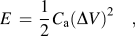
where m is the carbon mass of one electrode, i is the discharge current, dV/dt is the slope of the discharge curve, C a is the areal capacitance, and ρ is the areal mass loading. The calculated areal capacitance and specific capacitance values for current densities between 1.78 and 21.33 mA/cm2 are shown in Fig. 4(c). The highest areal capacitance of 1.37 F/cm2 (specific capacitance: 23.83 F/g) was obtained at a current density of 1.78 mA/cm2, which is much higher than previously reported results for different nanocarbon structures and peseudocapacitive oxides.Reference McDonough, Choi, Yang, La Mantia, Zhang and Cui11, Reference Frackowiak14–Reference Weng, Su, Wang, Li, Du and Cheng16 The chrysanthemum-like nanocarbon foam demonstrates larger areal capacitance because of the larger mass of loading (∼30 mg/cm2). CV measurements are conducted on a control sample of pristine nickel foam to rule out its effects on the final specific capacitance [see Fig. 4(d)]. Measurements verify that the capacitance effect from the nickel foam is negligible, which further confirms that it only functions as a current collector. Based on the areal capacitance values from the CD curves, the energy and power densities of the SCs were calculated by using Eqs. (3) and (4):
 $$E\, = \,{1 \over 2}C_{\rm{a}} (\Delta V)^2 \quad,$$
 $$P\, = \,{E \over t}\quad,$$
where E is the energy density per area, C a is the areal capacitance value, ∆V is the potential range, P is the power density per area, and t is the total time of discharge. Hence, a high energy density value of 0.191 Wh/cm2 for the SCs was obtained with our chrysanthemum-like nanocarbon foam electrodes, and this gradually reduced to 0.11 Wh/cm2 with an increase in the power density from 7.36 to 141.77 W/cm2 [Fig. 4(e)]. The high areal capacitance, energy density, and power density in regular aqueous electrolyte suggest that these chrysanthemum-like nanocarbon foam electrodes are excellent candidates for future electrochemical capacitors.
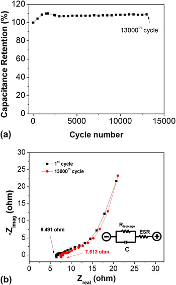
Long cycling life is also one of the most important metrics in the application of SC electrodes. A test sequence of 13,000 charge–discharge cycles for SCs based on the chrysanthemum-like nanocarbon foam electrodes was carried out with a current density of 21.33 mA/cm2 [Fig. 5(a)]. The capacitance enhancement of the device in the first 1,500 cycles is due to the increased effective interfacial area between the chrysanthemum-like nanocarbon foam structures and the electrolyte with an increase in the reaction time.Reference Fan, Yan, Zhi, Zhang, Wei, Feng, Zhang, Qian and Wei20 This self-strengthening mechanism and superior cycling stability (∼100% capacitance retention over 13,000 cycles) demonstrate the excellent electrochemical performance of this type of electrode materials for applications in practical energy storage devices.
(a) Cyclic stability of the 3D CCNF bundle foam electrode at the current density of 21.33 mA/cm2. (b) A plot of the potentiostatic EIS measurements conducted between 0.1 and 106 Hz with an amplitude of 10 mV of chrysanthemum-like CNFs foam after 1st and 13,000th cycle. The inset shows the equivalent simplified Randle’s model, where C is the ideal capacitance, ESR is the equivalent series resistance, and Rleakage is the leakage resistance.

Potentiostatic EIS measurements were conducted on the chrysanthemum-like nanocarbon foam electrodes [Fig. 5(b) and Fig. S3]. The inset of Fig. 5(b) shows a simplified Randle’s model, which is the most common model fitted to SC EIS spectra. The impedance plots indicate a relatively low ESR value (∼6.49 Ω). EIS measurements were performed on the same SCs after 13,000 cycles, which show a minor increase in the ESR value of 7.613 Ω. The EIS Nyquist plots show a pair of near consistent spectra for before and after cycle tests, which further demonstrate an exceptional electrochemical cycling stability for the SCs based on the chrysanthemum-like nanocarbon foams [Fig. 5(b)]. The excellent cycling performance achieved in our nanocarbon foam system can be attributed to (i) large surface area, (ii) porous structure of the nickel foam leading to 3D nanostructured foam, and (iii) inherent stability of the nanocarbon materials.
IV. CONCLUSION
In summary, a novel CCNF foam architecture is grown by chemical vapor deposition (CVD). This unique and highly porous material provides a facile, scalable, and low-cost opportunity for fabricating energy storage devices. The high areal specific capacitance value of 1.37 F/cm2 (specific capacitance: 23.83 F/g), energy density of 0.191 Wh/cm2, power density of 141.77 W/cm2, and high electrochemical stability suggest that this novel material has a superior per area capacitive performance. Controlling the loading mass of the nanocarbon architecture demonstrates the great potential for balancing the areal capacitance and the specific capacitance for SC applications. Our research provides a promising method for building superior nanocarbon architectures onto commonly used nickel foam materials toward high performance energy storage devices.