I. INTRODUCTION
In recent years, as weight reduction demand for automobile and aircraft body is becoming the world focus, magnesium alloys are becoming one of the key engineering materials due to their low density and high specific strength and stiffness. Reference Bae, Kim, Kim and Kim1,Reference Yang and Liu2 It has been demonstrated that rare earth (RE) metals are the most effective elements to improve the strength properties of magnesium especially. Reference Liu and Dong3,Reference Feyerabend, Fischer, Holtz, Witte, Willumeit, Drücker, Vogt and Hort4 Among different kinds of Mg–RE alloys, Mg–Gd–Y system is one of the most promising candidates due to its high specific strength at both room and elevated temperature, and better creep resistance than other Mg–RE alloys. Reference Liu and Dong3–Reference Mirza, Chen, Li and Zeng5 In the past few years, a number of investigations related to the microstructure and mechanical properties of the Mg–Gd–Y system have been reported. Given the results in the literature, Reference Feyerabend, Fischer, Holtz, Witte, Willumeit, Drücker, Vogt and Hort4–Reference Honma, Ohkubo, Kamado and Hono9 the Mg–10Gd–3Y–0.5Zr alloy exhibits higher strength and better ductility compared with the other Mg–Gd–Y alloy.
Due to their high chemical activities, however, magnesium and RE elements tend to oxidize rapidly and to burn in air to bring a lot of inclusions into the Mg melt during the alloy melting process inevitably. Reference Du, Wu and Nie10 It is known that these oxide inclusions can destroy the continuity of the magnesium matrix and thus significantly reduce the comprehensive properties of the Mg–RE alloys as the cradle of defects such as pores and cracks. Reference Gao, Wu, Ding and Zhu11,Reference Wu, Zhai, Zeng, Zhu and Ding12 Now the purification technology of Mg–RE alloy has become one of the key bottlenecks, which restrict its application in industry. Therefore, the purification technology for the melt body of magnesium alloy is the key for improving the quality of magnesium alloy material.
Refining technologies can be divided into two categories: flux-based technology and nonflux technology. The former conventional flux purification has always been considered the most effective purifying method because of its favorable refining ability and easy operation. However, to obtain the expected effects, the amount of fluxes is at least 2% (wt%), which results in severe environmental pollution and may increase the chance of additional flux inclusions. Sometimes large flux inclusions get trapped in magnesium, causing deterioration of certain mechanical properties. Therefore, the traditional flux-based refining techniques are not the optimal solution for magnesium melt purification. Nonflux recycling based on gas spraying, melt filtration, settling, etc. is a relatively new method to purify magnesium alloys. Recently, the gas bubbling as a nonflux refining method has attracted more and more attention due to its inclusion removing ability and excellent degassing capacity. Reference Xu, Wu and Gao13,Reference Zhao, Pan, Liao and Wang14 However, up to now, no research literature on the effect of gas bubbling refining process on the microstructure and mechanical properties of Mg–RE alloys is reported. In the present paper, rotating gas bubble stirring is used to refine Mg–10Gd–3Y–0.5Zr alloy melt. Through experiments, the effects of various gas bubbling parameters on purifying effectiveness, mechanical properties, and fracture behaviors of sand-cast Mg–10Gd–3Y–0.5Zr are studied.
II. EXPERIMENTAL
A. Smelting and refining processes
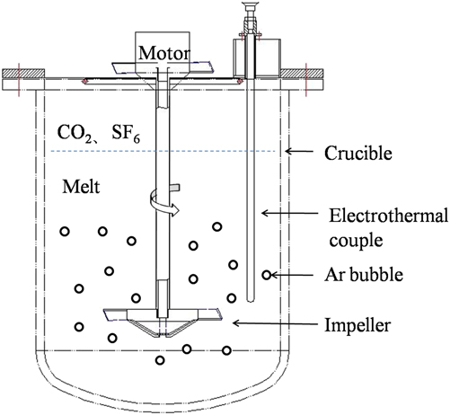
Mg–90Gd (wt%) and Mg–25Y (wt%) master alloys were made first by melting high-purity elemental Mg (>99.95%), Gd (>99.9%), and Y (>99.9%) in a vacuum medium-frequency induction furnace under an argon atmosphere. The alloying process with a nominal composition of Mg–10Gd–3Y–0.5Zr (named as GW103K, wt%) alloy was then prepared from high-purity Mg (99.95%), the Mg–90Gd (wt%), Mg–25Y (wt%), and Mg–30Zr (wt%) master alloys in a 7 KW electric resistance furnace under the mixed atmosphere of CO2 and SF6 with the ratio of 100:1. Reference Luo15 The total weight of the raw metal was 8 kg per charge. Then, at 740 °C, a rotary impeller Reference Xu, Wu, Liu, Zhang and Ding16 was inserted into the melt and then an inert gas, Ar, was introduced through the impeller hole, the size of which was 0.2 mm in diameter. The gas bubble stirring system is shown in Fig. 1. The rotating speed was 50–150 r/min. The gas flow rate was 1–5 L/min and the refining process lasts for 5–20 min. The speed of 150 r/min, flow rate of 2 L/min, and treating time of 10 min were chosen as the reference standard while investigating different parameters. During the whole refining procedure, the temperature was controlled at 740 ± 10 °C by an electrothermal couple immersed in the melt directly and the mixed protecting gas atmosphere discussed before is also indispensable.
Schematic drawing of rotating impeller gas bubbling system.

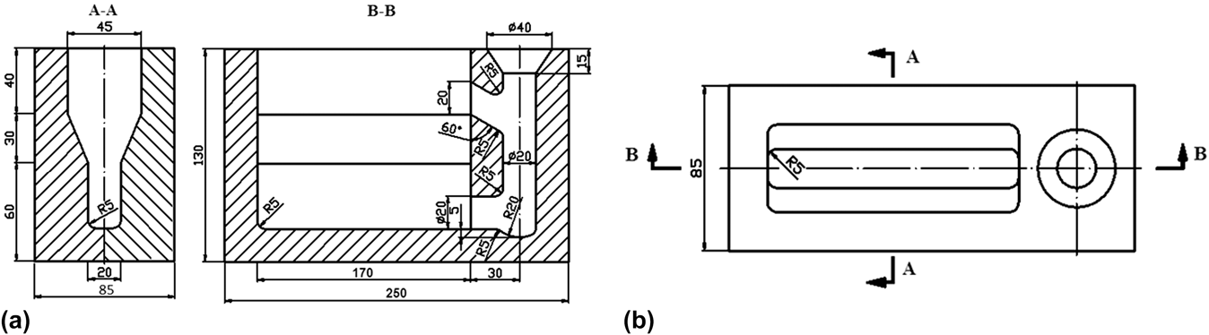
After refining treatment, the melt was held about 25–40 min, and then, at 720 °C, casted in sand molds of 130 mm × 250 mm block shape (see Fig. 2). The actual chemical compositions of the alloy were determined by an inductively coupled plasma analyzer (ICP, Perkin Elmer, Plasma-400, Waltham, MA).
Three view drawing of the casting mold. (a) side view and front view; (b) vertical view.

B. Properties test
Based on the experimental results in Ref. Reference He, Zeng, Peng, Gao, Nie and Ding17, the T6 heat treatment (solution treatment followed by artificial aging, 525 °C × 12 h + 250 °C × 10 h) was applied to these cast ingots, which were named as sand-cast-T6. Sheet tensile samples of 3.5 mm width, 2 mm thickness, and 10 mm gage length were cut from the casting ingots by the electric-sparking wire-cutting machine. Tensile testing was carried out under certain heat-treatment conditions at room temperature at a strain rate of 5 × 10⁻⁴ s−1 using a Zwick/Roell Z020 tensile machine (Zwick Roell Group, Ulm, Germany) according to ASTM: E8M-13a. The tensile properties reported under each condition, namely, ultimate tensile strength (UTS), tensile yield stress (TYS) at a 0.2% offset strain, and fracture elongation (El) are the average values of six test sheet samples.
Statistical volume fractions of nonmetallic inclusions and area fractions of the eutectic phases in alloys were measured with Image-Pro Plus software. The phase composition was scanned by a Rigaku Dmax-rc x-ray diffractometer (XRD) using Ni-filtered Cu Kα radiation. Phase analyses were performed with a Rigaku Dmax-rc XRD using Ni-filtered Cu Kα radiation and based on the document of the PDF 2 powder XRD database. The 2-theta range was 10–90° with a step size of 0.02° and a count time of 4 s per step. The microstructures, chemical composition analysis, and tensile fracture surfaces of the investigated alloys were observed by using optical microscope (OM) and scanning electron microscope (SEM, Philips 505, Holland), respectively.
III. RESULTS
A. Effects of Ar flow rate on purifying effectiveness and mechanical properties
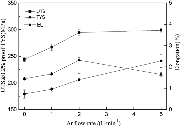
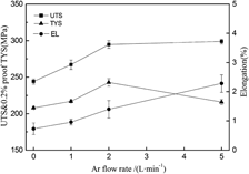
ICP measurement indicates a composition of Mg–10.18Gd–2.85Y–0.42Zr (wt%), which is very close to our expectation (Mg–10Gd–3Y–0.5Zr). This means that our method is acceptable for the preparation of samples. Figure 3 shows the effects of gas bubbling Ar flow rate on mechanical properties of the sand-cast-T6 alloys. It can be seen that the ultimate UTS and TYS of the alloy increase continuously with the change in the flow rate from 0 to 2 L/min. When the Ar flow rate is 2 L/min, the UTS and TYS increase from 244.3 and 208.5 MPa to 296.6 and 242.7 MPa, respectively. It indicates a 21.4 and 16.4% improvement for UTS and TYS, respectively. However, when the flow rate increases to 5 L/min, TYS exhibits a sudden slip while the UTS improves little (TYS: 216.3 MPa and UTS: 298.8 MPa). It should be noted that the decreased TYS still precedes that of the unrefined one. It can also be seen from Fig. 3 that the EL increases with the increasing flow rate.
Effects of gas flow rate on mechanical properties of the sand-cast-T6 GW103K alloy.

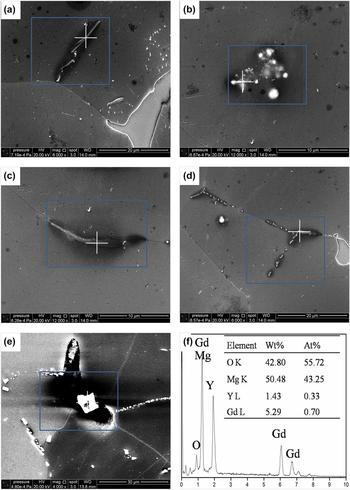
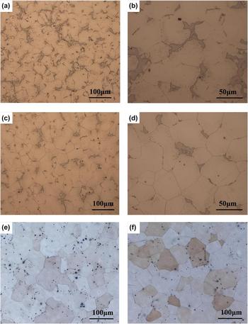
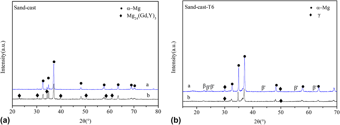
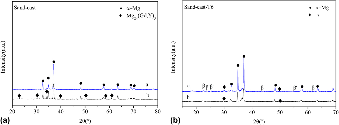
For the unrefined alloys, inclusions with different morphologies and sizes are illustrated in Fig. 4. Through SEM and EDX analyses for many view fields of the unrefined sand-cast specimens, it is indicated that the inclusions are mainly nonmetallic inclusions, that is, Mg, Gd, and Y oxide inclusions; meanwhile, MgO inclusions are perfectly dominant, consistent with Ref. Reference Liang, Wu, Ding and Wang18. Figure 5 shows the metallographic photograph of the specimens with (2 L/min) and without gas bubbling treatment. From Figs. 5(a) and 5(c), it is known that the gas bubbling treatment can significantly decrease the amount of the eutectic phases (Mg24(Gd,Y)5 illustrated in Fig. 6 of sand-cast XRD atlas) as well as the nonmetallic inclusions for the sand-cast GW103K alloys. The corresponding statistical analyses show that compared with the inclusion and eutectic phase content percentages of unrefined sand-cast GW103K alloy, which is 0.47 and 4.92%, respectively, the fraction of the gas bubbling one shows a significant reduction (inclusions: 0.32% and eutectic phases: 3.21%). As for the sand-cast-T6 ones, comparatively clean melt can also be achieved with the gas bubbling process [see Figs. 5(e) and 5(f)]. The corresponding XRD analysis result of the sand-cast-T6 alloy is shown in Fig. 6. As seen in the atlas, there are γ phase and β′ phase (i.e., Mg5(Gd, Y) precipitates) besides α-Mg supersaturated solid solution in the sand-cast-T6 alloy, i.e., the microstructure of the sand-cast-T6 alloy mainly consists of α-Mg + γ + β′. It indicates that the phase composition does not change with the refining process.
SEM images of nonmetallic inclusions in unrefined sand-cast GW103K alloy: (a) rod-like; (b) clusters; (c) needle-like; (d) discontinuous line; (e) block shape. (f) Energy dispersive x-ray (EDX) analysis of inclusions.

Microstructures of GW103K alloy under different conditions: (a) sand-cast, unpurified; (b) magnified view of (a); (c) sand-cast, gas bubbling refined; (d) magnified view of (c); (e) sand-cast-T6, unpurified; (f) sand-cast-T6, gas bubbling refined.

XRD analysis of the (A) sand-cast and (B) sand-cast-T6 GW103K alloy under different purifying treatments: a – unpurified and b – gas bubbling purification.
From all results, it is known that the favorable flow rate of 2 L/min can remove nonmetallic inclusions from the melt thus improving the mechanical properties.
B. Effects of Ar spraying time on purifying effectiveness and mechanical properties
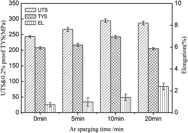
A comparison of the tensile properties for GW103K alloy under different Ar spraying times is shown in Fig. 7. As can be seen from Fig. 7, the mechanical properties show a continuous improvement with the appropriate increase in the Ar spraying time. The TYS and EL increase from 244.3 MPa and 0.7% to 296.6 MPa and 1.4%, respectively, when the treatment of 10 min rotating gas bubble stirring was used. This means that this process provides a certain refining action in which the nonmetallic inclusions and dissolved gas may be floated to the top of the melt and subsequently nonmetallic inclusion skimmed off. However, UTS will slightly decrease with further increase in the spraying time to 20 min. The result also shows that a long spraying time is detrimental to TYS.
Effects of Ar spraying time on mechanical properties of the sand-cast-T6 GW103K alloy.

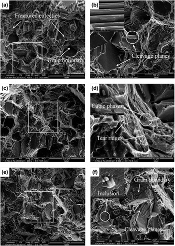
Figure 8 shows the fracture surface SEM micrographs of the tensile specimens of the sand-cast-T6 GW103K alloys in various conditions. In the untreated alloy [see Figs. 8(a) and 8(b)], we can see that there are intergranular fracture mechanisms. The fracture planes are cracked along the crystal interface, which is indicated by the arrow. In addition, the whole failure surface is composed of massive cleavage planes and grain boundaries. While a proper gas bubbling process (flow rate: 2 L/min, spraying time: 10 min, and rotating speed: 150 r/min) was applied, less cleavage planes, more tear ridges are found comparatively in the purified specimen, so that the fracture mode is quasicleavage fractures. When the alloy was subjected to the overtime (20 min) gas bubbling treatment, the fracture surface is mainly composed of cleavage planes, the same as that of unrefined alloy. Some nonmetallic inclusions can be found in the fractured planes, which indicates that a close relationship between nonmetallic inclusions and the fracture pattern for microcrack may partly form from the inclusions and then progresses across the grains as cleavage fracture.
Typical SEM images showing the fracture surfaces of tensile tested (a) unrefined alloy, (b) magnified view of the boxed region in (a); (c) gas bubbling (10 min) purified alloy, (d) magnified view of the boxed region in (c); (e) overtime gas bubbling (20 min) purified alloy, (f) magnified view of the boxed region in (e).

Overall, the best combination of mechanical properties and fracture behavior can be achieved by the 10 min gas bubble stirring treatment.
C. Effects of rotating speed on purifying effectiveness and mechanical properties
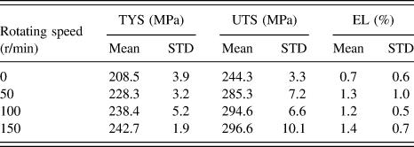
Under the experimental parameters, the mechanical test results of different rotating speeds are listed in Table I. With the increasing speed of rotary shaft, the refining effect is improved. Both the tensile strength and El exhibit a continuous growth trend. The large improvements in the UTS and TYS are observed through the 50 r/min gas bubble stirring refining process compared with the unrefined alloy, which are 285.3 MPa, 228.3 MPa and 244.3 MPa, 208.5 MPa, respectively. The UTS and the TYS reached to 294.6 and 238.4 MPa when the treatment of 100 r/min rotating gas bubbling was used. It improves little, however, with continuous increase in the rotating speed to 150 r/min (UTS: 296.6 MPa, TYS: 242.7 MPa). It indicates that 150 r/min is the most efficient rotating speed for the present work and further improvement in the speed has lost its industrial value. It should also be noted that the EL of the GW103K alloy is not so sensitive to the rotating speed and changes little with the increasing speed.
Tensile properties of the sand-cast GW103K alloys with different rotating speeds.

STD refers to the standard deviation from the mean value.
IV. DISCUSSION
A. Mechanism of inclusion–bubble interaction
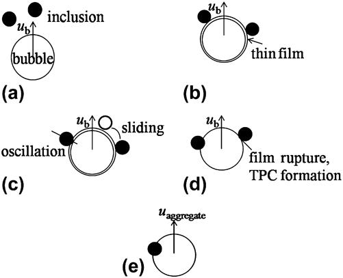
If it is assumed that the mechanism of inclusion–bubble interaction is similar to that of particle–gas interaction in water based mineral processing systems Reference Zhang and Taniguchi19 (see Fig. 9), then the inclusion removing process can be understood as follows: the inclusion approaches the gas bubble [Fig. 9(a)], collision occurs, and a thin liquid melt film builds up [Fig. 9(b)]. There are two modes of inclusion movement on the surface of the bubble, oscillation and sliding [Fig. 9(c)]; eventually, the inclusion will become attached to the bubble surface then float up or slide away and detach [Figs. 9(d) and 9(e)]. The clusters slag observed in the melt surface partly forms from the melt surface oxidization and partly from the nonmetallic inclusions wetted by Ar gas, then float up. And the floating process can be explained by the following analysis.
Subprocesses of particle removal by bubble floatation in mineral processing (u b bubble floating velocity; u aggregate aggregation floating velocity; and TPC three-phase contact). (a) approach of a bubble to an inclusion; (b) formation of a thin liquid film between inclusion and bubble; (c) oscillation and/or sliding of the inclusion on the bubble surface; (d) drainage and rupture of the film with the formation of a dynamic three-phase contact (TPC); (e) flotation of the bubble-inclusion aggregate. I have illustrated these in the discussion A.

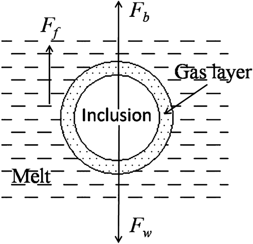
When further assumed that the successful attachment happened in subprocesses illustrated in Figs. 9(b)–9(d) once inclusions touched the gas and the gas around the inclusions, Reference Wu, Dai, Sun and Ding20 the stress condition of the single inclusion in the Mg melt can be shown in Fig. 10. According to the stress equilibrium relationship:
 $${F_{\rm{b}}} + {F_{\rm{f}}} = {F_{\rm{w}}}\quad {\rm{.}}$$
then,
 $$\left( {{V_{{\rm{inclusion}}}}{\rho _{{\rm{inclusion}}}} + {V_{{\rm{gas}}}}{\rho _{{\rm{gas}}}}} \right)g =\; V{\rho _{{\rm{metal}}}}g + {1 \over 2}{C_{\rm{d}}}{\rho _{{\rm{metal}}}}A{v^2}\quad {\rm{.}}$$
Schematic diagram of inclusion particle with gas covered (F b, particle buoyant force; F w, particle gravity force; F f, viscosity resistance).

Take the spherical particle as an example, then
 $${V_{{\rm{inclusion}}}} = {4 \over 3}\pi r_{{\rm{inclusion}}}^3\quad {\rm{,}}$$
 $$V = {4 \over 3}\pi {r^3}\quad {\rm{,}}$$
 $$V_{{\rm{gas}}} = V - V_{{\rm{inclusion}}} \left( {r > r_{{\rm{inclusion}}} } \right)\quad {\rm{,}}$$
 $$A = \pi {r^2},\,\;{C_{\rm{d}}} = {{24} \over {{R_{\rm{e}}}}},\;\;{R_{\rm{e}}} = {{2rv{\rho _{{\rm{metal}}}}} \over {{\eta _{{\rm{metal}}}}}}\quad {\rm{.}}$$
It can be deduced as given below:
 $$v = {{2g} \over {9{\eta _{{\rm{metal}}}}r}}\left[ {r_{{\rm{inclusion}}}^3\left( {{\rho _{{\rm{incusion}}}} - {\rho _{{\rm{gas}}}}} \right) + {r^3}\left( {{\rho _{{\rm{gas}}}} - {\rho _{{\rm{metal}}}}} \right)} \right]\quad {\rm{,}^{19}}$$
Reference Zhang and Taniguchi19 where v is the particle settling velocity; g is the gravity acceleration; ηmetal is the viscosity coefficient; r inclusion is the inclusion particle radius; r is the radius of aggregate of inclusion absorbing gas; ρinclusion is the inclusion density; ρgas is the gas density; and ρmetal is the metal density. V inclusion is the inclusion particle volume; V is the volume of aggregate of inclusion absorbing gas; V gas is the gas particle volume; C d is the drag coefficient; A is the projected area of a particle; and R e is the Reynolds number.
As the assumption made before, after Ar gas spraying into the Mg melt, the inclusion particles are wetted by gas, then r increases. The very small inclusions have the very small radius r inclusion, and r increases with the gas bubbling process. In this case, according to Eq. (7), ρinclusion−ρgas is positive while ρgas−ρmetal is negative. If the r inclusion is small enough and the r is big enough, the v result might be negative, which means that these inclusions will not settle, but float up.
B. Efficiency of rotating gas bubble stirring
The results show that the different rotating gas bubbling parameters have a close link with the refining efficiency. In fact, a gas injection process in melt refining focused on achieving two conditions: Reference Zhang and Taniguchi19,Reference Zhang, Taniguchi and Matsumoyo21 fine bubbles and good mixing. During Mg melt secondary refining, finer bubbles provide a larger gas-inclusion interfacial area and higher attachment probability of inclusions to bubbles. Good mixing enhances the efficiency of the transfer of the alloy elements as well as the inclusions. High-level of the Ar gas flow rate and rotating speed combined with the rotor–stator unit provides intensive melt shearing, resulting in the formation of fine Ar bubbles by effective dispersion and distribution. The rotating gas bubble stirring device can provide not only intensive shearing of the melt for dispersive mixing which disperse and transform the large bubbles to fine bubbles, but also a forced macroflow in the melt for distributive mixing, which distributes bubbles uniformly in the melt. Reference Zuo, Jiang, Zhang and Fan22 Therefore, when the optimal parameters of the rotating gas bubble stirring was used, the small, uniform, and well-distributed Ar bubbles can be obtained, resulting in shorter diffusion distance of inclusions in the melt and consequently higher diffusion rate. Thus, it improves the nonmetallic inclusion removal efficiency and leads to good mechanical properties.
Given the same wetting ability of gas bubbles, the lower level rate will cause the inefficiency of the refining process. If the flow rate is too high, although the refining ability is relatively improved, the surface oxidation will be raised. Sufficient time is necessary to produce enough fine bubbles and ensure the inclusion removal ability. However, the overtime treatment is meaningless and may induce the additional oxide to the clean melt and then decrease the mechanical properties. Under higher rotating speed, the higher impacting force is acted on melt. Therefore, the melt inclusion particles may be broken into debris and the gas bubble size becomes smaller. This can increase the gas-inclusion interface area and thus, improving the chance of inclusions wetted by gas bubbles. Accordingly, high rotating speed may produce high nonmetallic inclusion removing efficiency and mechanical properties.
V. CONCLUSIONS
A continuous nonflux refining process has been developed for Mg–10Gd–3Y–0.5Zr alloy. The process involves introducing Ar into the Mg–10Gd–3Y–0.5Zr melt and creating fine bubbles and good mixing between gas and liquid metal, which can highly increase the efficiency of impurity removal. In the present work, the microstructure, mechanical properties, and fracture behaviors of the Mg–10Gd–3Y–0.5Zr alloys with different rotating gas bubble stirring parameters were investigated. The following conclusions can be drawn:
-
(1) Too high or too low Ar flow rate will lead to relatively poor mechanical properties. Given the same wetting ability of gas bubbles, the lower level rate will cause the inefficiency of the refining process. If the flow rate is too high, although the refining ability is relatively improved, the surface oxidation will be raised.
-
(2) Ar spraying process with the high rotating speed could produce high nonmetallic inclusions removing efficiency and mechanical properties. Enough Ar spraying time should be guaranteed. However, the overtime rotating gas bubble stirring process will decrease the mechanical properties.
-
(3) The nonflux purification method of rotating gas bubble stirring is an effective new method in purifying Mg–10Gd–3Y–0.5Zr alloy. When the combination of the optimal parameters (Ar flow rate: 2 L/min, time: 10 min, and rotating speed: 150 r/min) was applied, the volume fractions of nonmetallic inclusions in the unrefined alloy can be reduced significantly from 0.47 to 0.32%, where clean melt can be achieved. Correspondingly, the UTS, TYS, and EL reached to 296.6 MPa, 242.7 MPa, and 1.4%, respectively, compared with 244.3 MPa, 208.5 MPa, and 0.7% of the unrefined one.
-
(4) The rotary injection Ar refining process would not change the phase composition but it does have a certain effect on the fracture pattern of the Mg–10Gd–3Y–0.5Zr alloy.
ACKNOWLEDGMENTS
This project is sponsored by Funded Projects of SAST-SJTU Joint Research Centre of Advanced Aerospace Technology (No. USCAST2012-15), Shanghai Rising-Star Program (B type, 14QB1403200), and Research Fund for the Doctoral Program of Higher Education of China (Nos. 20120073120011 and 20130073110052).