Introduction
High-entropy alloys (HEAs) or multi-principal element alloys are a relatively recent category of materials wherein the principal constituent elements are added in equimolar or near equimolar concentrations [Reference Yeh, Chen, Lin, Gan, Chin, Shun, Tsau and Chang1, Reference Cantor, Chang, Knight and Vincent2, Reference Gao, Liaw, Yeh and Zhang3, Reference Miracle and Senkov4]. Nearly 15 years of research on various such alloys has generated a wealth of data and understanding of their alloying behavior and structure–property relationships. Notably, the AlCoCrFeNi family of alloys has been studied extensively. Information on phase evolution in equiatomic AlCoCrFeNi [Reference Zhang, Zhang, Chen and Cao5], via different processing routes (both liquid and powder metallurgy) [Reference Wang, Wang, Wang, Tsai, Lai and Yeh6, Reference Manzoni, Daoud, Volkl, Glatzel and Wanderka7, Reference Ji, Fu, Wang, Wang, Zhang, Wang and Zhang8, Reference Uporov, Bykov, Pryanichnikov, Shubin and Uporova9, Reference Vaidya, Prasad, Parakh and Murty10, Reference Shivam, Basu, Pandey, Shadangi and Mukhopadhyay11], their corresponding mechanical properties (both in compression and in tension) [Reference Wang, Li, Ren, Yang and Fu12, Reference Tang, Senkov, Parish, Zhang, Zhang, Santodonato, Wang, Zhao, Yang and Liaw13, Reference Jiao, Wang, Wu and Qiao14, Reference Mohanty, Maity, Mukhopadhyay, Sarkar, Gurao, Bhowmick and Biswas15, Reference Ghassemali, Sonkusare, Biswas and Gurao16], their oxidation behavior [Reference Butler17, Reference Dabrowa, Cieslak, Stygar, Mroczka, Berent, Kulik and Danielewski18] as well as their tribological properties [Reference Zhang, Han, Su and Meng19] is well documented in the literature. Promising reports on HEA nitride coatings [Reference Huang and Yeh20, Reference Pogrenbjak, Yakushchenko, Bondar, Beresnev, Oyoshi, Ivasishin, Amekura, Takeda, Opielak and Kozak21] and HEA compositions outshining commercial alloys’ oxidation resistance [Reference Huang, Zhang, Shen and Vilar22] have triggered the community’s interest in the coating aspects of HEAs and the possibility of considering them for potential commercial applications. One such potential application is as a bond coat in thermal barrier coating systems (TBCs) employed in jet engines. The role of bond coats in TBCs is primarily to protect the superalloy turbine blade from oxidation at operating temperatures above 1000 °C [Reference Padture, Gell and Jordan23].
In connection with this, there has been some work reported in the literature on the well-studied equiatomic quinary alloy AlCoCrFeNi, synthesized via mechanical alloying, and coated on steel substrates via atmospheric plasma spraying (APS) [Reference Ang, Berndt, Sesso, Anupam, Praveen, Kottada and Murty24]. It was observed that significant melting and oxidation of the alloy powder occurred during the spraying process, with concurrent transformations in the alloy phases in the coating. The resultant coating had a composite alloy–oxide microstructure, which exhibited poor oxidation resistance, thus making the combination of AlCoCrFeNi and APS impracticable. To counter this issue, the coating technique has been changed to cold spray using the same alloy composition as the feedstock.
Cold spray, as the name indicates, falls on the lower-temperature side of the thermal spray processes spectrum [Reference Moridi, Hassani-Gangaraj, Guagliano and Dao25]. Herein, the powder particles are introduced and accelerated by a heated (<1000 °C) high-pressure gas mixture. This gas is then made to travel through a De-Laval type converging–diverging nozzle, accelerating the gas to speeds of Mach 1 and above [Reference Alkhimov and Anatoly26]. At particle speeds above a certain “critical velocity” (characteristic for a feedstock–substrate combination, particle size, and shape), the particles’ kinetic energy gets converted to impact energy when they strike the substrate. This whole process is accompanied by severe plastic deformation at the particle–substrate interface along with localized heat generation, allowing the particle to bond mechanically to the substrate [Reference Assadi, Gartner, Stoltenhoff and Kreye27]. It is important to note that the particles are never heated directly, and thus any temperature-triggered phase transformations are prevented. Besides, even though the spraying is done in open air, there is practically no oxidation of the powder, and the alloy is thus faithfully reproduced in the coating [Reference Stoltenhoff, Kreye and Richter28].
Over 150 reports are available in the literature on HEA coatings, synthesized via the more popular laser cladding and sputtering (primarily for HEA nitride and carbide coatings) techniques, as well as by other thermal spray methods such as plasma spray and HVOF [Reference Zhao, Ma, Wang, Li, Chen and Zhou29]. However, the advantage of cold spray in retaining the inherent alloy feedstock properties remains unmatched among all. This is one of the first reports on cold-sprayed HEAs, focusing on Al-containing compositions, and the results are encouraging toward considering these materials and methodology not only as high-temperature oxidation-resistant coatings, but also for other compositions [Reference Yin, Li, Song, Yan, Kuang, Xu, Wen and Lupoi30] and other low-temperature applications.
In the present study, AlCoCrFeNi alloy powder particles were sprayed onto stainless steel and Ni-based superalloy substrates under various gas temperature and pressure conditions. Subsequently, one optimized spraying condition on superalloy substrate was selected, isothermal oxidation was carried out at 1100 °C for 25 h, and the oxidized microstructure was analyzed comprehensively to understand the oxidation mechanism.
Results and discussion
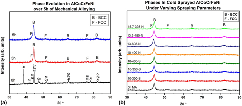
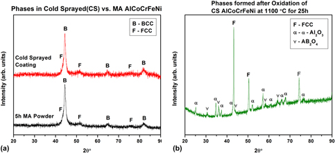
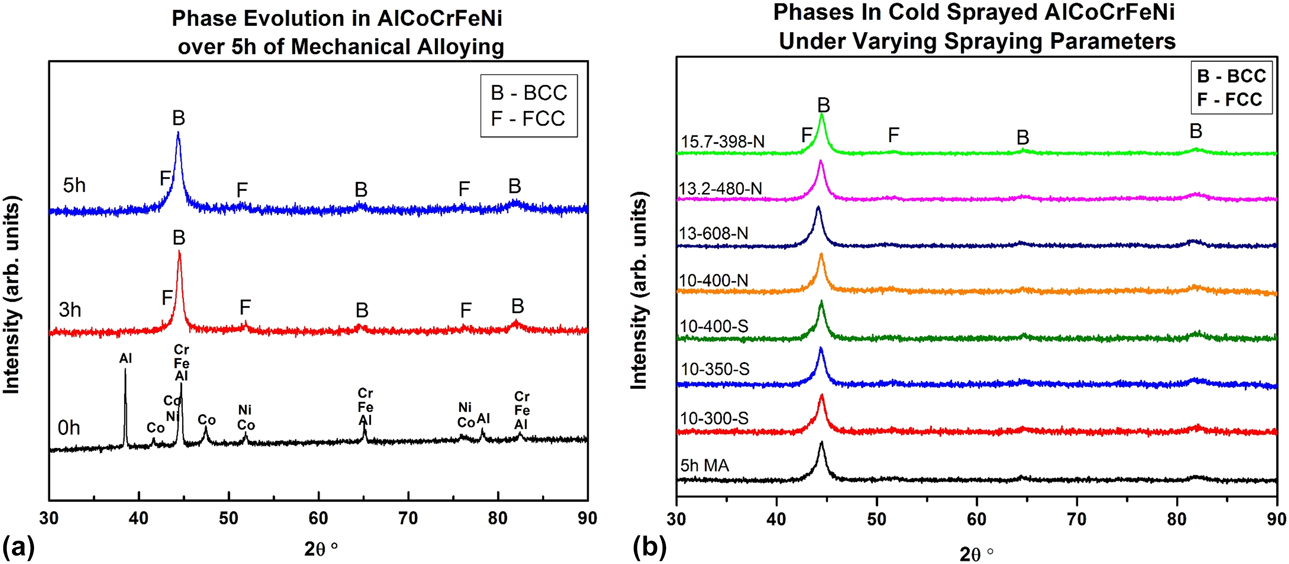
The XRD patterns illustrating the phase evolution in AlCoCrFeNi after 5 h of mechanical alloying are shown in Fig. 1(a). After the fifth hour, only peaks corresponding to a major BCC and a minor FCC phase are visible, and no residual elemental peaks are discernible. Based on the high negative mixing enthalpy of Al with Ni, Co, and Fe, it is anticipated that these elements contribute to the BCC lattice, while a combination of Ni, Co, and Fe, which form an FCC at high temperatures [31], is likely constituting the FCC phase. There is also the possibility of a Fe–Cr BCC phase, but owing to its peak positions (44.125°, 64.178°, 81.176°) in close proximity to those of Ni–Al (44.426°, 64.628°, 81.788°), and the broadening of peaks due to nanocrystallinity and microstrain, it is challenging to identify its peak from XRD.
(a) Phase evolution in AlCoCrFeNi over 5 h of mechanical alloying showing the formation of a major BCC and minor FCC phases; (b) comparison of the phases observed in cold-sprayed AlCoCrFeNi under various spraying conditions versus 5 h MA powder illustrating the retention of the same phases after cold spray.
The limited number of available reports on mechanically alloyed AlCoCrFeNi indicates that the phase formation and evolution are dependent on the milling parameters, such as wet/dry milling, milling media, and the duration of milling. Zhu et al. [Reference Zhu, Liu and Ye32] reported a single-phase FCC alloy after 72 h of dry milling, whereas it took 20 h of wet milling for Kumar et al. [Reference Kumar, Swarnakar and Chopkar33], 24 h for Chen et al. [Reference Chen, Niu, Wei, Hao, Liu, Wang and Peng34], and 30 h for Ji et al. [Reference Ji, Fu, Wang, Wang, Zhang, Wang and Zhang8] and Shivam et al. [Reference Shivam, Basu, Pandey, Shadangi and Mukhopadhyay11] to obtain a single-phase supersaturated BCC alloy. In another study, Mohanty et al. [Reference Mohanty, Maity, Mukhopadhyay, Sarkar, Gurao, Bhowmick and Biswas15] obtained a major FCC and minor BCC phase after 25 h of dry milling. Vaidya et al. [Reference Vaidya, Prasad, Parakh and Murty10], whose milling parameters (wet milling and WC milling media) were similar to the present study, reported that the phases formed and their fractions can be controlled by the variation of the sequence in which elemental powders are added. However, interestingly, the results of all (except one) of the sequences tried in their work (milling up to a maximum of 70 h) resulted in a combination of a major BCC and a minor FCC phase (with varying fractions), which is consistent with the present study.
Based on the dissolution of elemental peaks, and constraint by the limitation to avoid fine particle size, and to prevent contamination (C and WC), milling was stopped after 5 h. Crystallite size of the BCC phase after 5 h was calculated to be 11 ± 1.0 nm (using the 110 peak after deconvolution), while the average particle size (d 50) was 7 µm (d 10 = 4.5 and d 90 = 15 µm).
A variety of gas temperature and pressure conditions were used to spray AlCoCrFeNi on two different substrates of stainless steel (SS 304) and a Ni-based superalloy (Hastelloy® X C-263), as explained in the previous section. The phase evolution of AlCoCrFeNi after cold spraying under various gas temperature and pressure conditions is illustrated in the XRD patterns of Fig. 1(b) (“N” stands for Ni-base superalloy substrate and “S” stands for stainless steel substrate). No significant difference can be seen in the phases formed after coating under varying conditions and the 5 h MA powder [Fig. 1(a)]. There was no observable difference in the peak positions, phase fractions, or crystallite sizes in all the coating conditions. Similarly, no additional peaks corresponding to any new phases were seen. These observations suggest that the phases in the MA powder are retained as such in the coating under various spraying parameters.
Shivam et al. [Reference Shivam, Basu, Pandey, Shadangi and Mukhopadhyay11] observed via in situ XRD experiments that the supersaturated disordered BCC solid solution is not thermally stable and starts to precipitate as Ni3Al-type L12 phase above 350 °C and further transforms to ordered B2, L12, and tetragonal (sigma) phases between 500 and 800 °C. However, in the present study, in spite of the gas temperatures applied in the experiment being in the range of 300–600 °C, no phase transformations are observed in the coating, which suggests that the powder itself does not get heated to the process temperature and that the (metastable) phases formed after MA are carried over to the coating as such. Further, no oxidation of the powder took place during cold spray, as indicated by the absence of oxide reflections in Fig. 1(b).
Microstructural characterization of cold spray coating of AlCoCrFeNi
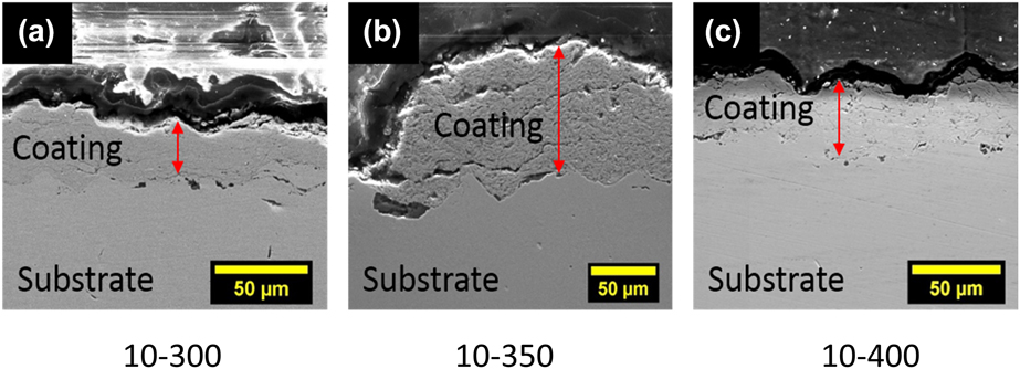
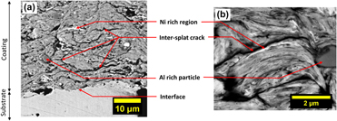
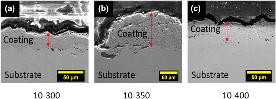
Cross-sectional back-scattered SEM micrographs of the coatings deposited under the gas temperature in the range of 300–400 °C are shown in Fig. 2. (In this manuscript, the trial conditions are referred as pressure–temperature–substrate combinations such as 10-300-S (10 bar and 300 °C on stainless steel SS304), 10-350-N (N refers to Ni-based superalloy Hastelloy X C-263), 10-400-S, and so on.) Some features common to all the conditions are as follows: nonuniform coating thickness and a rough coating surface, a good interface between coating and the substrate, discontinuous cracks across the coating parallel to the interface, low intersplat porosity, and the absence of oxide stringers between the splats. The microstructure of the coating condition 10-400-N was studied in detail and is shown in Fig. 3.
Cross-sectional views of cold-sprayed AlCoCrFeNi under varying spraying conditions: (a) 10 bar and 300 °C; (b) 10 bar and 350 °C; (c) 10 bar and 400 °C.
A detailed analysis (common to all other spraying conditions) of the 10-400-N condition showing inhomogeneity in the coating along with intersplat cracks and porosity at (a) lower and (b) higher magnifications.
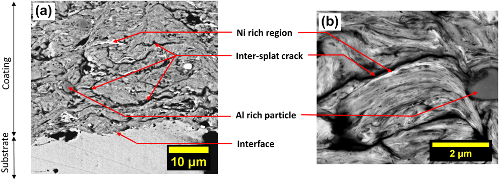
At higher magnifications and using the BSE mode, atomic number contrast becomes apparent in the coating cross-section. Figure 3(a) shows fine regions rich in Ni (bright contrast) and possibly undissolved Al particles (dark contrast). This suggests that even though the absence of elemental peaks in the XRD of 5 h MA powder implied that pure elements had dissolved and formed the alloy, complete alloying has not occurred at a finer scale. Possibly, a tiny fraction (<5 wt%) of the undissolved elements remaining is the reason for those reflections not being visible in the 5 h XRD pattern. Besides, the peaks of Ni interfere with those of the Ni–Co–Fe phase and hence could not be distinguished.
A still higher-magnification micrograph in Fig. 3(b) reveals an individual splat, possibly an erstwhile particle, where very fine striations of dark and light gray phases show that the extent of alloying is almost complete, but not quite finished. These coatings have an average hardness of 3.8 ± 0.2 GPa and, having a major BCC phase, might be brittle relative to the substrate. The intersplat cracks could be the result of deformation without conformity or a cohesively unbonded zone which appears due to the domination of elastic rebound energy over plastic dissipation energy. It is believed that as the particle size decreases, the critical velocity of bonding increases [Reference Papyrin, Kosarev, Klinkov, Alkimov and Fomin35]. It is especially pertinent here since the average size of MA particles is much lesser than usually used. On the other hand, the steel/superalloy substrates, being more ductile than HEA, deformed preferentially when hit by the first layer of particles, allowing them to form strong mechanical bonds, resulting in an excellent coating–substrate interface.
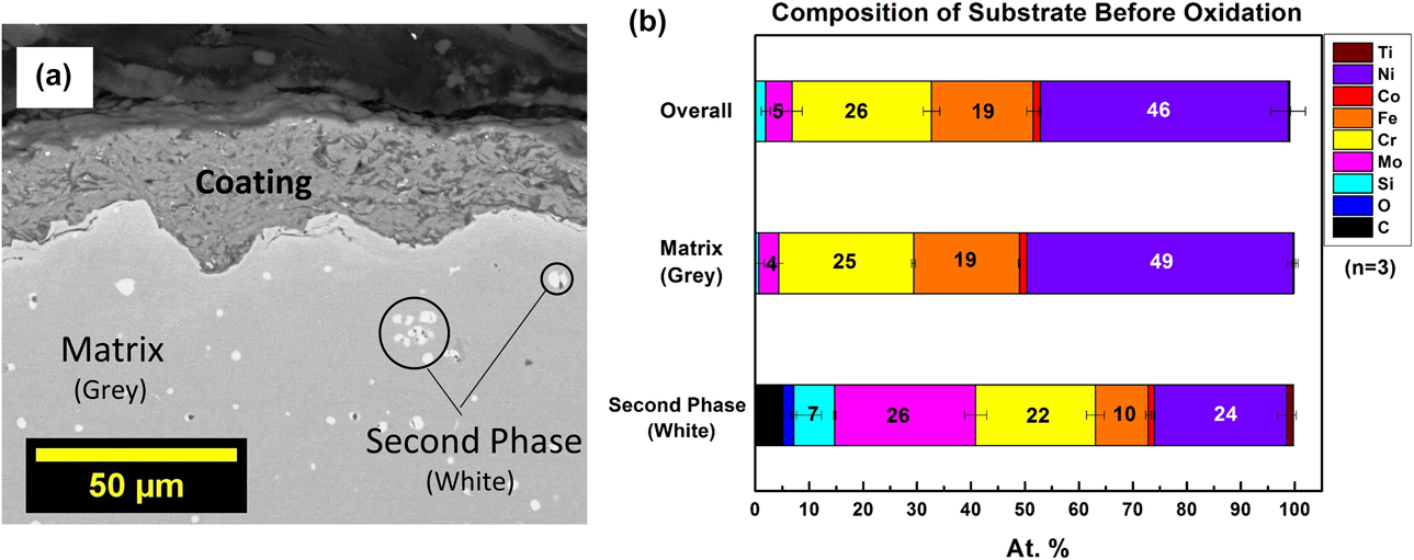
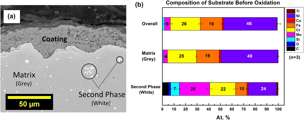
The AlCoCrFeNi 10-400-N coated on the Ni-based superalloy Hastelloy® C-263 was oxidized isothermally, as stated above. In addition to the cold spray coating undergoing significant changes due to oxidation, there can be consequential microstructural changes in the substrate and at the coating–substrate interface due to the interdiffusion between coating and substrate. To understand these microstructural changes near the coating–substrate interface as well as away from the interface (but within the substrate) during oxidation, it is necessary to know the reference microstructure of the substrate before oxidation. Thus, the cross-sectional microstructure of the substrate before the oxidation is elucidated in Fig. 4(a), and phase-wise compositions, as well as the overall composition, are shown in Fig. 4(b). It may be noted that the Ni-base superalloy substrate is characterized as a two-phase microstructure, with a Ni–Cr–Fe-based matrix with little (4 at.%) Mo content and a second white phase distributed randomly all through the matrix, which is significantly richer in Mo and Si than the substrate. The distribution of the white phase along the interface is also not uniform.
Elemental distribution in the superalloy substrate before oxidation: (a) BSE-SEM micrograph of cross-sectional microstructure showing the two phases; (b) the phase-wise composition and overall composition of the Ni-base superalloy substrate.
Microstructural characterization of the oxidized cold spray coating of AlCoCrFeNi
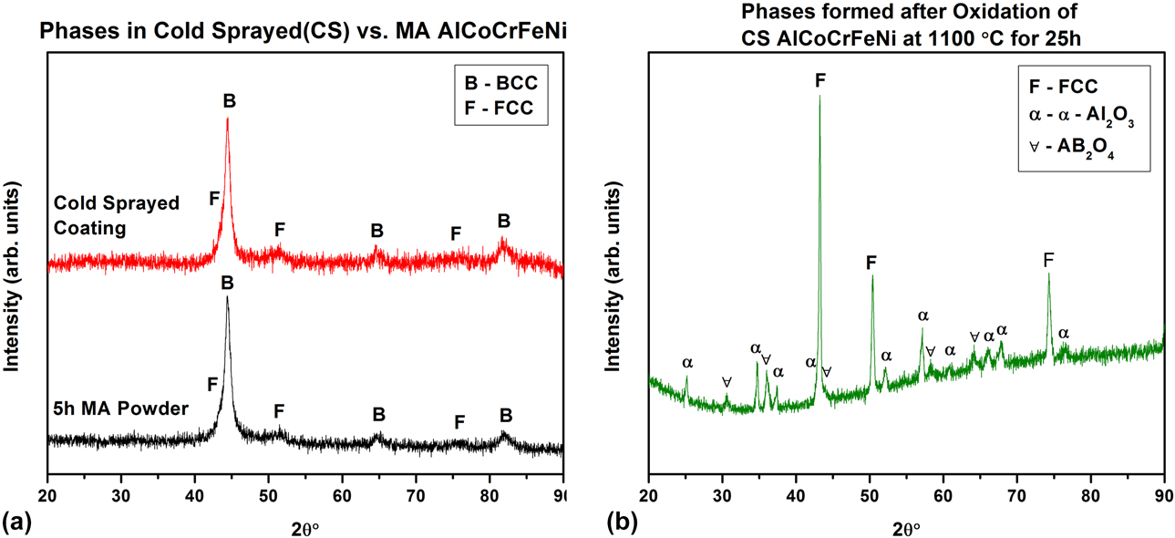
Figure 5 illustrates the XRD patterns taken on the top surface of the coating before [Fig. 5(a)] and after [Fig. 5(b)] its oxidation at 1100 °C. It is well established in the HEA literature that Al acts as a BCC stabilizer [Reference Wang, Wang, Wang, Tsai, Lai and Yeh6], and the same is evidenced in the unoxidized coating. However, when this alloy is exposed to a high-temperature oxidizing atmosphere, Al, Cr, and Fe (in the order of stable oxide formation according to the Ellingham diagram) tend to oxidize preferentially. Alpha alumina and spinel (AB2O4 type) peaks seen in Fig. 5(b) are proof of this behavior, while the concurrent loss of Al from the BCC phase resulted in an FCC CoCrFeNi [Reference Wang, Wang, Wang, Tsai, Lai and Yeh6] alloy below the oxide layer. It is also known that Cr oxidizes to Cr2O3, which volatilizes to CrO3 at temperatures above 1000 °C [Reference Tedmon36]. It is challenging to monitor/capture this process in experiments such as this, but it is quite possible that this influences the oxidation behavior of the HEA.
Phases in the coating: (a) before oxidation showing that the phases from MA are retained even after cold spray and (b) after oxidation illustrating the disappearance of BCC phase together with the formation of alumina and spinel.
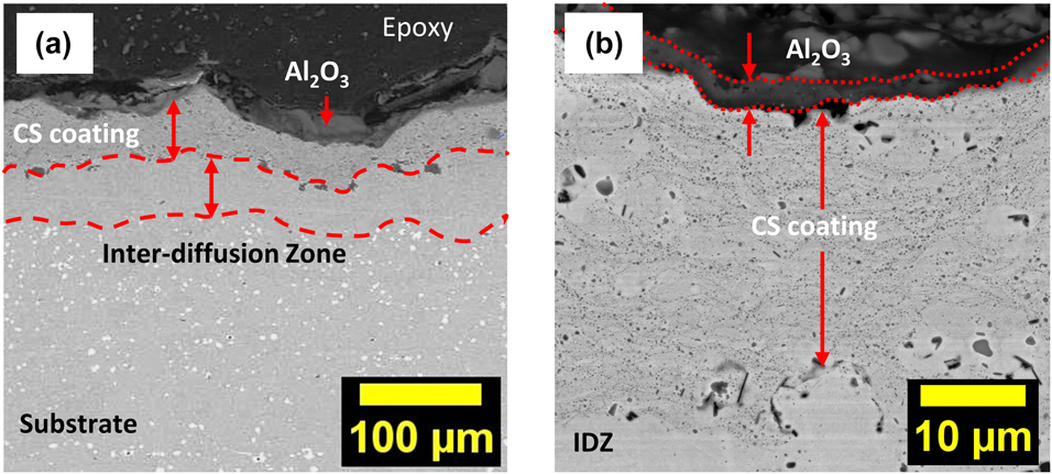
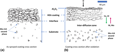
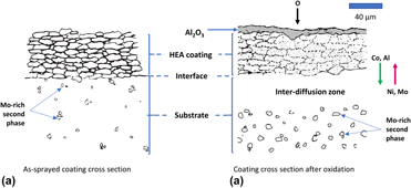
The features observed based on the close inspection of the cross-sectional BSE-SEM micrographs of the oxidized sample [Figs. 6(a) and 6(b)] are as follows: (i) a thin alumina layer is observed to be adhered to the top of the CS coating, especially in the valleys; (ii) there is no oxide layer either discrete or continuous at the interface of CS coating–substrate; (iii) there is a zone adjacent to the interface in the substrate that is noticeably depleted in the Mo–Si-rich white phase, whereas the distribution is unaffected farther away from the interface (this region has been termed as an interdiffusion zone (IDZ) and will be discussed in detail shortly); and (iv) the coating and the oxide layer appear to have sustained some damage during cross-sectional sample preparation. A schematic of the coating cross-section before and after oxidation, summarizing these features, is depicted in Fig. 7 (the scale bar shown in the schematic is just for reference purposes).
BSE-SEM micrographs of cross-sectional microstructure of oxidized AlCoCrFeNi cold-sprayed coating showing (a) the alumina layer, cold-sprayed coating, precipitate-free IDZ, and superalloy substrate; and (b) alumina layer and coating at a higher magnification illustrating the more densified coating as well as the pervasive alumina formation within the coating besides its formation on the top.
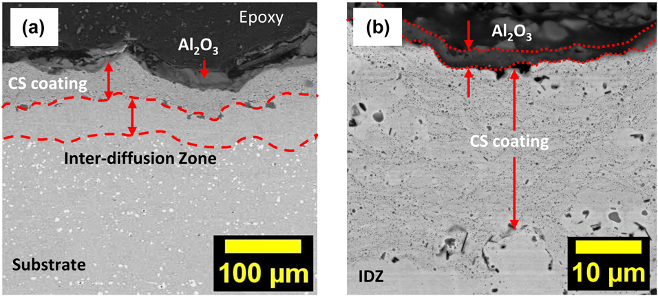
Schematic depicting (a) as-sprayed coating cross-section; (b) coating cross-section after oxidation, emphasizing (i) improved densification, (ii) alumina layer formation, and (iii) IDZ formation post isothermal oxidation.

The first encouraging inference from the above observations is that the current cold-sprayed AlCoCrFeNi coating oxidized to form an alumina layer, thereby successfully protecting the underlying substrate from oxidation at 1100 °C for 25 h continuously. Alumina formation is the mainstay of bond coats used in TBCs. The Al-containing bond coat oxidizes during service to develop a thin protective alumina layer (called TGO, or thermally grown oxide) which protects the substrate from high-temperature oxidation. The thickening or loss of the TGO is a known cause of TBC failure, emphasizing the vitality of TGO-forming bond coats [Reference Evans, Clarke and Levi37]. In this regard, our cold-sprayed AlCoCrFeNi coatings show some promise, which can definitely be improved further with better optimized coating parameters. The presence of a discontinuous alumina layer indicates that there was a protective oxide formed initially, but it either gets disrupted over time or is damaged during mechanical polishing.
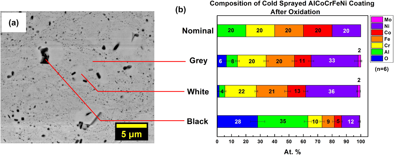
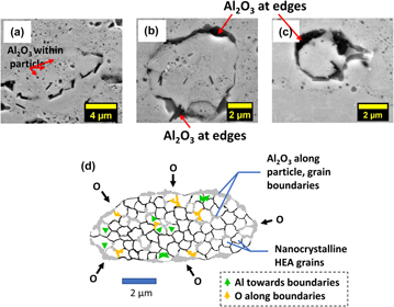
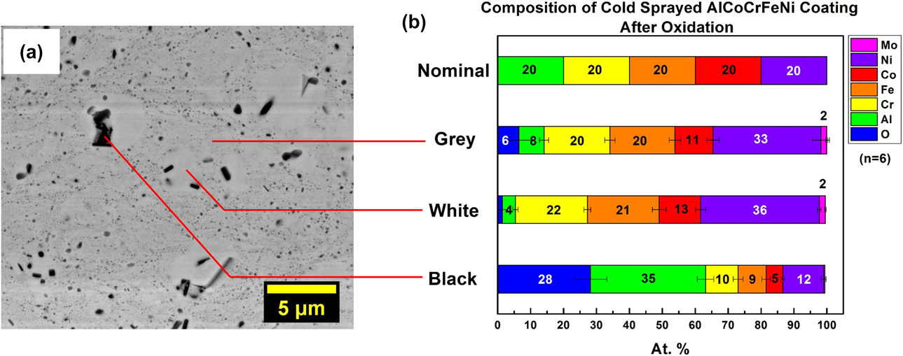
Higher-magnification micrographs of the cross-section of the oxidized coating reveal very finely distributed “black” regions. A small fraction of these “black” regions is expected to be coalesced pores left over from the intersplat boundaries after the long annealing treatment. The rest are confirmed as aluminum oxide particles using spot EDS, as shown in Figs. 8(a) and 8(b). These oxides show two different morphologies. The first type is small and spherical-appearing, the largest measuring ∼300 nm across, present as a fine decoration around erstwhile particle boundaries, and possibly nanocrystalline. The second type is rod-shaped, the largest measuring ∼1 µm in length and 0.4 µm across. Further, the two contrasts labeled “gray” and “white” in Fig. 8 have nearly the same composition, with the “gray” phase containing some oxygen, while the “white” phase doesn’t. It is likely that the “gray” phase is essentially a composite of the dark phase distributed in a fine form in the “white” phase. The aluminum levels in Fig. 8(b) indicate a significant loss in the alloy from the starting amount (20 at.%) to the one in the white phase, which corresponds to the FCC AlxCoCrFeNi (x < 0.5) phase observed in the oxidized XRD pattern [Fig. 5(b)]. Also, there are white regions entirely free from the fine oxide specks, although usually in the vicinity of a larger oxide particle(s) (rod-shaped morphology), where it appears that preferential oxidation has occurred.
Phases observed in the cross-section of (a) oxidized coating, and (b) their composition depicting the extensive formation of alumina within the coating after oxidation for 25 h at 1100 °C. Some of the “black” regions also correspond to the coalesced pores left over from the intersplat boundaries.
It can be hypothesized that the way oxidation of this coating system occurred is largely a function of the following factors: (i) grain size of the alloy, which is nanocrystalline here; (ii) the aluminum content of the alloy—20 at.%; (iii) porosity and cracks in the coating (∼7% here); (iv) oxygen content of the atmosphere and its partial pressure; (v) test temperature—1100 °C; and (vi) diffusivities of the involved elements.
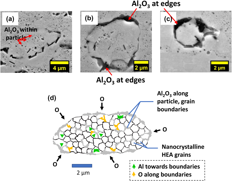
Oxygen initially interacts with all the oxide-forming elements available on the surface (transient oxidation) and subsequently would form alumina during the steady state [Reference Wagner38]. While this process is in progress, concomitantly oxygen that enters the coating would interact with Al present in the grains within the coating. Understandably, oxidation preferentially occurs at the higher-energy nanocrystalline grain boundaries, resulting in the fine nearly spherical dispersion, as shown in Fig. 9(a). Over time, as more oxygen enters the coating, larger oxide stringers begin to form, preferably at the particle boundaries [Figs. 9(b) and 9(c)]. Gradually, as the entire particle surface gets oxidized, it is possible that the volume mismatch between alumina and neighboring alloy, upon rapid cooling from 1100 °C to room temperature, causes the alumina-covered particle to detach from its surroundings and appear as pullouts. In the absence of an impervious alumina layer covering the coating, or due to the presence of cracks and porosity in the oxide layer, some degree of internal oxidation will continue. It can be extrapolated from this that failure may result from cracks propagating along such large defects, eventually causing the spallation of the coating. Figure 9(d) succinctly presents this oxidation mechanism outlining, within a single splat (erstwhile particle), the role of nanocrystalline grains, and allowing additional oxygen pathways into the splat, resulting in oxidation both at the splat edge and within. Scale bar shown in the schematic is just for a reference purpose.
A possible mechanism of internal oxidation and eventual failure of cold-sprayed AlCoCrFeNi coating: (a) initial oxidation at the grain boundaries and starting along particle boundaries, (b) alumina rods grow at particle surface, (c) alumina completely covers the particle leading to pullouts; (d) schematic of the mechanism showing the diffusion pathways within an individual splat, with oxygen diffusing along the grain boundaries and Al diffusing toward the grain boundaries, leading to the formation of alumina along the surface and within the splat.
Microstructural changes in the substrate after oxidation
Another exciting feature was the presence of a single-phase zone in the substrate adjacent to the coating–superalloy interface [Fig. 6(a)]. Prior to oxidation [Fig. 4(a)], there was no such region, and the Mo-rich second phase was distributed randomly across the substrate. However, the second phase particles were absent in the substrate near the interface after oxidation. Moreover, spot EDS of the oxidized coating detected up to 2 at.% Mo dissolved in the alloy, which indicates that the dissolution of the second phase near the coating–substrate interface and the diffusion of Mo upwards into the coating have occurred.
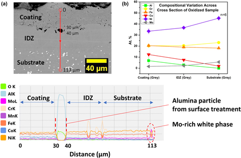
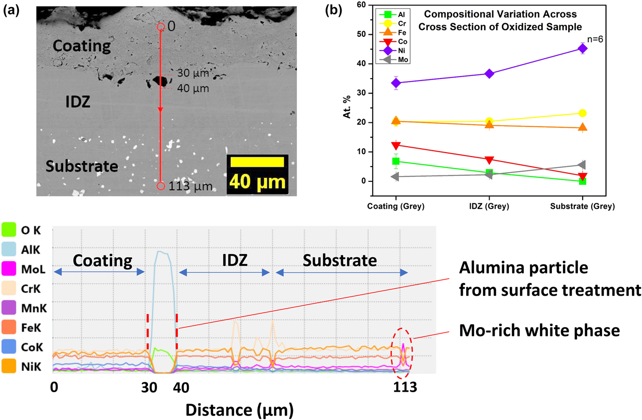
As reported in the literature [Reference Pomeroy39], in a bond coat over the Ni-based superalloy system (bond coat–superalloy system), the diffusion of rare earth elements toward the bond coat and concurrent diffusion of Pt/Co/Al downwards into the substrate lead to the formation of brittle topologically close packed phase (TCPs) in the substrate. These TCPs are undesirable as they compromise the load-bearing capability of the superalloy part, by depleting the rare earth elements (W, Re, Ta) that are added originally for solid solution strengthening [Reference Pomeroy39]. However, in the present study, no TCPs were observed. Instead, Mo dissolved and diffused into the coating, producing a single-phase zone in the substrate near the coating interface. A line scan across the cross-section [Fig. 10(a)] also revealed an increased Ni content in the coating, from 20 at.% in the MA HEA powder [not shown in Fig. 10(b)] to 34 at.% in the coating after oxidation, and of Fe, Co, and Cr in the substrate. This two-way diffusion is the reason for this zone to be labeled as the IDZ. Figure 10(b) gives the reader an idea of the concentration gradient left after oxidation, with the diffusion of Ni and Mo from the substrate to the coating, and of Co and Fe vice versa.
(a) Line scan showing the compositional gradients across the oxidized coating–IDZ–substrate; (b) Ni content in the coating has increased to 34 at.% from 20 at.% in the MA HEA powder (starting composition of MA powder has all elements 20 at.%, not shown in this figure), along with 2 at.% Mo, both diffused from the substrate.
Although the IDZ might have a lower mechanical strength due to the lack of the second phase reinforcement, it might be more ductile and may be able to absorb some of the volumetric strains generated during thermal cycling. While the diffusion of other elements into the coating is expected, the presence of Mo (being a refractory element) in the coating is unanticipated. Additionally, nanocrystallinity of the HEA grains and the presence of porosity and cracks in the coating may have further accelerated Mo diffusion into the coating. The recent literature by Vaidya et al. [Reference Vaidya, Pradeep, Murty, Wilde and Divinki40] on the FCC CoCrFeNi and CoCrFeMnNi systems and Li et al. [Reference Li, Chen, Zhong, Zhang, Chen and Liu41] on the FCC AlCoCrFeNi system concluded that diffusion in HEAs cannot be considered sluggish and is dependent on the elements present in the alloy. Specifically, Vaidya et al. [Reference Vaidya, Pradeep, Murty, Wilde and Divinki40] observed a higher diffusion for a 5-component alloy in comparison to a 4-component alloy at higher temperatures, while Li et al. [Reference Li, Chen, Zhong, Zhang, Chen and Liu41] observed a significantly slower diffusion only for Cr and Fe in their alloy. Our observations concur well with the literature while showing the lack of sluggish diffusion in a real-life application.
Conclusions
The results of oxidation of the cold-sprayed AlCoCrFeNi are encouraging, albeit generating several fascinating questions. The following conclusions are based on the understanding that is gained based on the detailed analysis presented above.
(1) Cold spray is a viable and potentially powerful coating technique for generating HEA coatings while retaining the inherent alloy phases in the coating. Such a one-to-one correlation allows one to leverage the advantage of interesting properties of HEAs in the form of coatings.
(2) Equiatomic AlCoCrFeNi was coated successfully onto various substrates under varying conditions, and the coatings were found to be identical phase-wise.
(3) Coating parameters can be fine-tuned further to reduce the intersplat porosity and get better interparticle bonding.
(4) AlCoCrFeNi was successful in preventing the substrate oxidation at 1100 °C for 25 h. Better oxidation resistance can be promised with better coating quality [Reference Kaur, Kumar, Sharma, Kim, Kumar, Chavan, Joshi, Singh and Singh42].
(5) Coating underwent some internal oxidation possibly due to the extensive grain boundary network in the nanocrystalline powder and porosity in the coating.
(6) Mo dissolution from the substrate near the interface and formation of an IDZ indicate that the diffusion is not sluggish in the complex alloy lattice of HEA.
Further work is focused on improving the coating quality by optimizing the process parameters, besides tweaking the HEA composition keeping the bond coat applications in mind. Thermal cycling tests and longer duration (200–500 h) studies will be instrumental in developing a comprehensive understanding of coating oxidation behavior in conditions close to real-life applications. It will be interesting to see the interplay between the various affecting factors leading to the optimum oxidation-resistant HEA coating.
Experimental materials and procedures
Elemental Al, Co, Cr, Fe, and Ni powders (Loba Chemie Pvt., Ltd., Mumbai, India, 99.5% purity) were mechanically alloyed in Fritsch Pulverisette P5 ball mills (FRITSCH GmbH, Idar-Oberstein, Germany) for 5 h. Tungsten carbide balls were used as the milling medium with a 10:1 ball-to-powder ratio in a WC vial, and toluene was used as the process control agent. Milling was restricted to 5 h to prevent further reduction in the powder particle size, since a too fine particle size will result in powder loss during spraying, and cold spray requires the particle size to fall between 1 and 50 µm. Besides, wet milling for longer durations often results in undesirable carbon and WC contamination from the PCA and milling medium, respectively, which can affect the alloy properties adversely [Reference Praveen, Anupam, Tilak and Kottada43]. Coatings were deposited with compressed air as the process as well as the powder carrier gas, with an in-house cold spray system at the International Advanced Research Center for Powder Metallurgy and New Materials (ARCI), Hyderabad, India, with a proprietary nozzle onto SS304 and Hastelloy® X C-263 substrates procured from MIDHANI, Hyderabad, India. Prior to deposition, all the substrates were grit-blasted using an alumina grit (50 mesh) at 3 bar blasting pressure. Gas temperature was varied from 300 to 600 °C, and gas pressure in the range of 10–15 bar. The distance between the nozzle exit and surface of the substrate was fixed at 15 mm. Microstructural characterization of all the milled powders and coatings was carried out using a Panalytical X-Pert Pro X-ray diffractometer (Malvern Panalytical Ltd., Royston, U.K.), and SEM on FEI Inspect F (Thermo Fischer Scientific, Hillsboro, Oregon) equipped with an EDAX (AMETEK Materials Analysis Division, Mahwah, New Jersey) spectrometer. Vickers hardness measurements were made on the coating cross-section using a Wolpert Wilson Vickers microhardness machine (INSTRON DEUTSCHLAND GmbH, Aachen, Deutschland) at loads of 25 gf and a dwell time of 10 s. The particle size of the milled powders was measured using a Microtrac Particle Size Analyzer S3500 (Microtrac Inc.) using ethanol as a dispersant and with two minutes of ultrasonication before measurement.
Based on various trials, the 10-400-N (10 bar and 400 °C on Ni-base superalloy substrate) set of coatings was chosen as a representative of cold-sprayed AlCoCrFeNi coatings and oxidized in a laboratory scale muffle furnace in air at 1100 °C for 25 h in a continuous isothermal fashion. Samples measuring 1 × 1 × 0.5 cm were cut from the coated coupons using a slow-speed diamond saw, placed in prefired alumina crucibles, and introduced into the furnace already set at the test temperature. After 25 h of oxidation, the sample along with the crucible was taken out from the furnace and allowed to cool in the air for 15 min. The SEM images of the coating cross-section were taken in both secondary (SE) and back-scattered (BSE) modes. For viewing the cross-section of the coated and oxidized samples, the entire sample was double-mounted, i.e., it was first mounted in Bakelite with the oxidized coating facing Bakelite and then cut using a slow-speed diamond saw. This cut section was mounted again for the second time, and the cross-section was polished to mirror finish before viewing under SEM. Weight gain measurements were not carried out in this study because the substrate would also get oxidized along with the coating, as only one surface is coated, and the oxidation of coating cannot be separated in that case.
Acknowledgment
The authors would like to acknowledge the financial support from the Aeronautics Research and Development Board (ARDB), India, via the project “Development of High Entropy Alloy (HEA) coatings as potential bond-coat materials for high temperature turbine engine applications” (sanction # ARDB/GTMAP/01/2031783/M/1/285/D(R&D)). Authors also thank Mr. Ashish Bharadwaj for assistance with the graphics.