I. INTRODUCTION
Due to their complexity and large electrical size, phased array antennas are challenging structures for numerical full-wave simulation. Given their unique ability to redirect radiated energy quickly and without mechanical motion, phased arrays are prevalent, particularly in military applications. Although specifications for military hardware are not typically published, visual inspection of publically available images reveals that a 50 element ×50 element array is not unusual. Given a nominal element size of 0.5 wavelength, this means an effective electrical area of 625 square wavelength beyond the capacity of current full-wave solvers.
The infinite array is an effective idealization when a large planar array is regular – that is, the array elements are arranged in a periodic lattice. Fortunately, since the regularity assumption allows a single-element design, such arrays are common. The analysis of the array may then be reduced to a single representative unit cell. A number of successful numerical approaches have been demonstrated for analysis of the unit cell. Among those employing the finite-element method representative examples are [Reference McGrath and Pyati1, Reference Jin, Lour, Li, Riley and Riley2].
Despite the success of the unit cell approach, its field solution neglects the “edge effect” – variation in the cell-by-cell field solution due to the finite size and termination of the array lattice. This is especially true for array sizes less than 10 × 10. For this reason, a simulation encompassing the entire finite array is desired. Also, in a commercial implementation the ability to simulate an entire finite array is desirable since setup and extraction of antenna metrics do not require certain technical aspects of array theory required in the infinite array case. Thus, the technical burden is shifted from the user to the software and the array analysis becomes more accessible for a non-specialist.
In recent years, the domain decomposition method (DDM) [Reference Zhao, Rawat, Lee and Lee3, Reference Vouvakis, Cendes and Lee4] has emerged as a powerful and attractive technique due to its inherent parallelism and capability of taking advantage of periodicity in antenna arrays. The basic idea of DDM is to decompose the original problem into smaller non-overlapping, and possibly repetitive, sub-domains and prescribe appropriate boundary conditions at domain interfaces to enforce tangential electric and magnetic field continuity. Each sub-domain problem is then solved in parallel to obtain initial solutions. These initial solutions are refined in parallel and the entire assembly is solved iteratively until equilibrium is reached between all domains. It can be proved that when the appropriate interface condition is employed, the iterative process in DDM will converge to the solution of the original problem [Reference Benamou and Després5]. Also, the interface conditions should be chosen so that each sub-domain problem is well-posed and the convergence of the DDM algorithm is optimal. Compared with the traditional finite-element method, the DDM solver offers much better parallel scalability while demanding much less memory.
In the present paper, we have extended the discussion of [Reference Manges, Silvestro and Petersson6] to connect and compare the classical infinite array analysis with that of finite arrays afforded by the DDM. Analysis of both types will be shown with data generated by the commercial finite-element field solver, High Frequency Structure Simulator (HFSS). In the conclusion of this paper, we make a recommendation for a design flow combining the two methods.
II. INFINITE ARRAY ANALYSIS VIA THE TRANSFINITE-ELEMENT METHOD (TFEM)
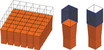
The TFEM [Reference Cendes and Lee7], a specialization of the three-dimensional finite-element method, has proven to be an efficient and robust tool for analyzing the unit cell of an infinite array. The method is distinguished by its discretization of modal boundary conditions using specially constructed global basis functions. The application to the unit cell of Fig. 1 may be summarized as follows.
Portion of an infinite array of square horns along with two views of a unit cell showing matching meshes.

The unit cell is terminated below and above by ports through which energy enters and leaves the cell volume. Below, at the array element feed port, the modal fields consist of incident and reflected guided-wave modes. Above, at the radiating end of the cell, is a “Floquet port” where the modal fields are plane waves with propagation direction determined by the array periodicity.
The sidewalls of the unit cell form “linked” boundaries that enforce the field periodicity determined by the array lattice. This is achieved by matching the meshes on master and slave surfaces.
The discrete field solution E h is formed using a tetrahedral volume mesh in concert with two kinds of basis functions. Those representing interior fields are the standard tangential vector elements W m. Thematic to the TFEM, additional special basis functions e nh are constructed to represent the port fields. Thus,

Here the unknowns E m represent the interior fields and a n and b n represent incident and emerging modal fields on the port boundaries. Appropriate normalization of the functions e nh allows elimination of a n and b n in favor of entries of a modal scattering matrix [S]. Since [S] is computed for a unit cell in an infinite periodic structure all incident mode sources are implicitly repeated throughout the infinite array and consequently [S] is an “active” scattering matrix.
Discretization of Maxwell's equations using (1) then leads to a matrix equation AX = B. The fact that two types of basis functions, interior and port are used implies that this equation has a 2 × 2 block structure with internal unknowns E and port (modal) unknowns [S].

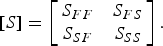
Solution of the matrix equation then directly yields the scattering matrix interrelating port unknowns and Floquet modes without any post-processing. Using the notation “F” to represent feed ports and “S” to represent Floquet ports, the (active) scattering matrix is partitioned in the following manner:
By appealing to classical array theory results, the scattering matrix elements may be used to determine important aspects of array performance, subject to the infinite array idealization. In particular:
(1) The active element pattern (AEP) of the array is proportional to the coupling between the port modes and the specular (TE00 and TM00) Floquet modes [Reference Galindo and Wu8]. The AEP is defined as the radiated field pattern of the array with a single element excited and the remaining elements match-loaded. Its significance in array analysis is well known. The particular entries of S SF, which relate port modes to the TE00 and TM00 Floquet modes, are proportional to the AEP.
(2) The composite array pattern for prescribed array excitations may be determined as the product of the AEP and a known factor depending only on array lattice geometry and frequency [Reference Stutzman and Thiele9].
(3) The passive port-coupling matrix of the array may be determined by a Fourier transform of the active reflection coefficient S FF as a function of scan angle [Reference Wu and Galindo10].
(4) The submatrices S FS and S SS contain the array response to incident plane waves, but will not be discussed further here.
III. AEP FOR INFINITE ARRAY
For an array element driven by a single feed mode, the precise relationship between the S SF entries S TE00,1, S TM00,1, and the spherical components of the AEP G ϕ, G θ is


where A is the unit cell area and λ is the wavelength in the global environment, typically vacuum. The pattern here is normalized to 1 Watt of incident feed power. The form of this relation also depends on the normalization selected for the Floquet modal functions. In this paper, the modal functions are normalized so that the specular modes carry 1 Watt of array normal-directed power at each scan angle.
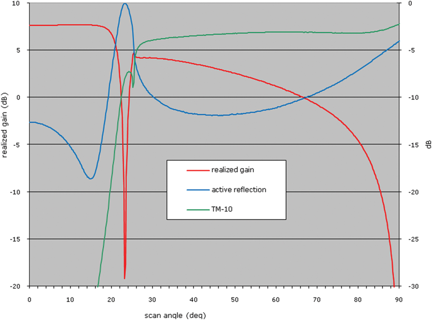
As a demonstration of the interplay of the active reflection and the AEP, the unit cell of an array of square flared horn array elements was analyzed for a sweep of scan direction extending from boresight to endfire. The horn element, shown in Fig. 1, has an aperture of 0.65λ × 0.65λ and the elements are spaced 0.70λ in both directions. This is the same array as described in Section 8.2 of [Reference Bhattacharyya11]. Two Floquet modes, the TM00 and the TM−10, were used to represent the Floquet port fields on the basis that each one is propagating for at least one scan angle in the 0–90° range. Floquet modes that were not included each had at least 18.5 dB of attenuation per unit length along the cell.
Figure 2 shows the computed results. The horizontal-axis doubles both as scan angle for the array and as pattern angle for the AEP, and extends from 0 (array normal direction) to 90° (array endfire), though this is much greater than the working range of most practical array elements. S-parameter magnitudes for active reflection and the port coupling to the TM−10 Floquet mode are plotted on the right vertical axis and the AEP, equal to the scaled coupling to the TM00 Floquet mode, is plotted on the left axis. The data shown in the figure match the results presented in Figure 8.2 of [Reference Bhattacharyya11].
Scan angle sweep for E-plane of horn array unit-cell showing realized gain (left-axis), active reflection and coupling to TM-10 mode (right-axis).
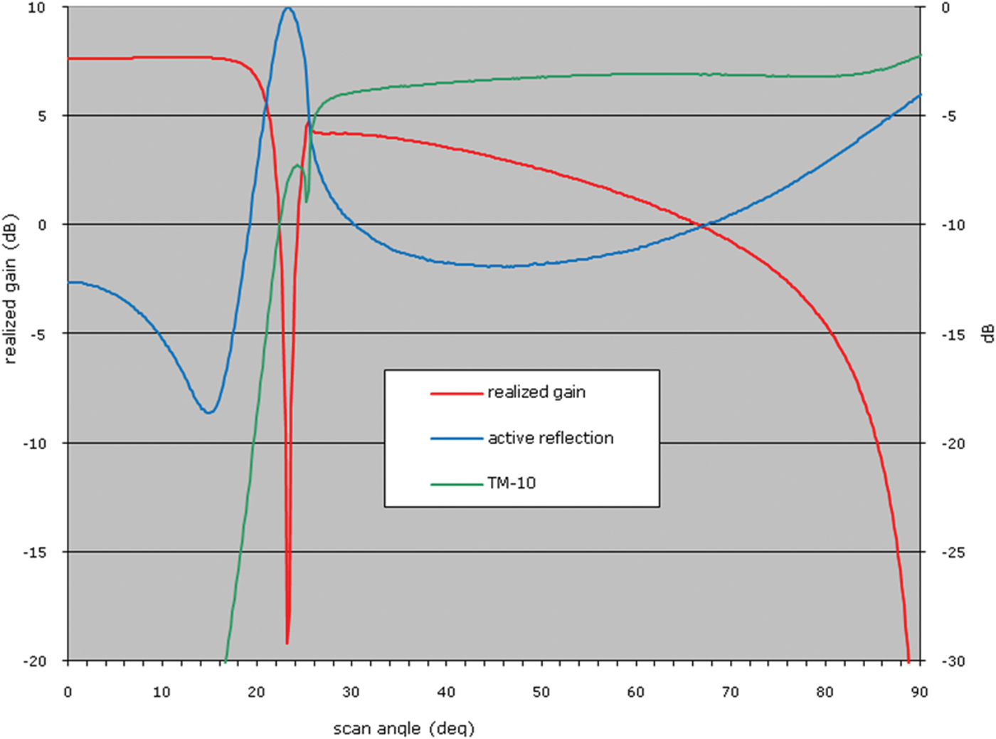
Several phenomena are apparent in the figure. The boresight active element realized gain is 7.65 dB and active reflection level is approximately −13 dB. As the scan angle is increased, a scan blindness condition at ≈23° is apparent from near-unity port reflection and the sharp dip in active element gain at the same pattern angle. At about 16° a grating lobe begins to appear in the form of the TM-10 Floquet mode. The TM-10 mode moves from cut-off to propagating just beyond the scan blindness angle. Since energy is then shared between the grating lobe (TM-10) and the main lobe (TM00), the main lobe diminishes and correspondingly the AEP gain reduces. Finally at endfire the original main lobe recedes and energy is balanced between reflection and grating lobe radiation.
Note that since the unit cell boundary conditions change as a function of scan angle, a separate field simulation is required for each scan angle considered in the figure. The time requirement for a scan angle sweep can be considerably reduced by using the adaptive interpolation method described in [Reference Manges, Silvestro and Petersson6]. Also, when multiple cores or CPUs are available, the simulations for different scan angles may proceed in parallel.
IV. DOMAIN DECOMPOSITION FOR FINITE ARRAYS
Next, we turn to the topic of simulating a finite array in its entirety. In this section, a DDM with non-overlapping Schwarz algorithm is described. To apply the DDM, the original problem domain Ω is first partitioned into N non-overlapping sub-domains:

In an antenna array problem, each element will naturally be a domain. In the ith domain Ωi, the boundary value problem (BVP) is written as
In Ωi:

On the interface Γi:

Note that an additional unknown carrying the physical meaning of electric current on the boundary, namely  is introduced on the domain interface Γi. Also note that
 is the electric field inside domain
 ,
 is the electric field on the boundary surface of Ωi, and
 is the outward normal of the ith domain. The superscript n stands for nth iteration of the alternating Schwarz algorithm. Finally, k, η, ɛri, and μri are the free-space wave number, impedance, relative permittivity, and permeability of the medium in the ith domain, respectively. Equation (7) is generally known as the Robin transmission condition. Its right-hand side is defined as

where neigh(i) indicates the neighboring domains of domain i. The above system corresponds to a Schwarz-type iteration scheme. We remark that the role of the Robin transmission is to enforce the necessary continuity of electromagnetic fields at the interfaces between adjacent sub-domains. For vector wave problems, it has been proved in [Reference Benamou and Després5] that the Robin-type transmission condition is necessary to ensure well-posed local problems and convergence of domain decomposition algorithm. For a recent comprehensive review on present DDMs, we refer interested readers to [Reference Vouvakis, Cendes and Lee4] and the references therein.
The system of equations (6,7) is appropriately tested through a Galerkin testing procedure, resulting in a matrix equation of the form

where Ki, yt are the system matrix and excitation vector for Ωi, respectively. Ki resembles a system matrix derived from traditional finite element method using a first-order absorbing boundary condition (ABC). The solution vector and right-hand side updating vector are given, respectively, as

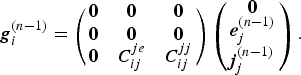
Note that at each iteration, the right-hand side of (9) (cf. (11)) is updated using only the information of surface unknowns. Thus, by introducing additional surface unknowns the information in the entire volume of a domain is translated into information on the boundary surface, resulting in a tremendous reduction in memory requirements. Furthermore, for an array problem where each array element is identical in terms of geometry, the system matrix Ki and excitation vector yi also remain the same for all domains that further reduces the memory requirements.
The iterative process in (9) is trivially parallelizable as new right-hand side (11) only requires information from the previous iteration. Significantly, the formulation presented here allows both conformal and non-matching meshes across interfaces between adjacent sub-domains. In our implementation, we have used matching surface meshes on master and slave boundaries similar to those used in the infinite array solver.
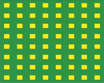
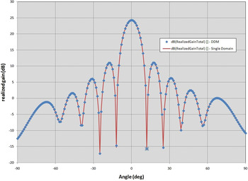
To illustrate the accuracy and efficiency of this new procedure, consider the simple patch array shown in Fig. 3. The element is a square patch with side length of 32 mm and truncated corners. It is fed by a coaxial line. The substrate is 5-mm-thick with relative dielectric constant of 3.27. The simulation frequency is 2.45 GHz and the array has equal spacing of 0.6 λ 0 in both x and y directions with 8 rows and 8 columns. For comparison, a complete model that contains the full 64-element array was also created. This model uses the same elements, but was simulated as a single domain. The E-plane pattern for the case of all elements excited with equal amplitude and 0° phase (broadside scan) is shown in Fig. 4. The single-domain simulation results are shown as a solid curve and the symbols show the results from the DDM simulation. The agreement is excellent.
Finite patch array.

Patch array E-plane patterns for a uniformly excited array.

The DDM simulation was performed on a Linux cluster using 100 engines. The average memory per engine was 336 MB and the total elapsed time was less than 15 min. To simulate the model on a single engine using the standard approach approximately 25 GB was needed and elapsed time was 6 h. This demonstrates that very large arrays can be simulated accurately and efficiently using the DDM.
V. INFINITE ARRAY RESULTS VERSUS FINITE ARRAY RESULTS
We now present a comparison of results from the infinite array and finite array approaches.
A) Convergence of AEP
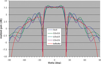
The square horn array of Fig. 1 can be used to demonstrate the proportionality between the Floquet transmission coefficient and the AEP. To provide a comparison, using the DDM method the E-plane cut was computed for a singly excited central element in a succession of finite arrays of increasing size. Figure 5 compares these pattern cuts with the port-to-TM00 Floquet mode coupling as a function of scan angle computed using the TFEM and unit cell. In particular, it can be noted how the sequence of finite arrays exhibits pattern dips of increasing depth at the null location predicted by the infinite array result shown in Fig. 2.
Active element realized gain for infinite array and center element of finite arrays.

B) Composite array pattern calculation
Using the AEP with a standard array factor (see [Reference Stutzman and Thiele9]), one can rigorously compute the composite pattern of an infinite array with a finite number of elements excited and the rest match-loaded. Since mutual coupling effects are included, this composite pattern acts as an accurate approximation of that of the finite array. In contrast, the use of an isolated element pattern instead of the AEP in this procedure should not be as accurate since the mutual coupling effects are not included.
However, use of the infinite array AEP does have a limitation. It does not rigorously include the edge effect and as seen in Fig. 5 the sharpness of the null at the scan blindness angle is more pronounced in the infinite array simulation than it appears in a finite array. Both of these effects become less important as the array increases in size. Therefore, one would expect the infinite array model to be reasonable for medium-sized arrays, and to be more accurate when considering very large arrays.
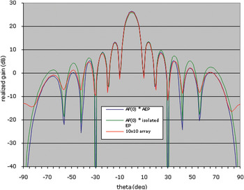
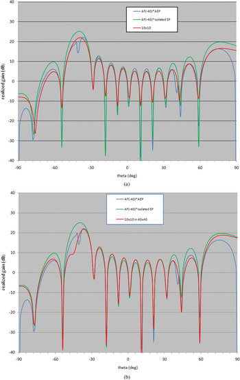
To show this, a medium-sized 10 × 10 array was considered. The same patch element described in Fig. 3 was used. For this element, there is a dip in the array pattern that appears at scans of ≈± 40°. The 10 × 10 array results for both 0 and −40° scans were computed and are shown in Figs 6 and 7a, respectively. The DDM approach was used to simulate the full finite array and those patterns are shown as the data labeled “10 × 10”. The corresponding patterns found using the array factor and the AEP and using the array factor and the isolated element pattern are also included. Even for this small array size it can be seen that the AEP with the array factor does show better agreement with the DDM array simulation results than the isolated element patterns with array factor. Neither the DDM array simulation results nor the isolated element pattern with array factor exhibit the sharp null seen in the AEP with array factor however.
Realized gain for boresight steer. Computed using array factor with AEP and isolated element pattern and compared with DDM finite array solution.

Realized gain for −40° steer. (a) Computed using array factor with AEP and isolated element pattern and compared with DDM finite array solution for a 10 × 10 array. (b) Computed using array factor with AEP and isolated element pattern and compared with DDM finite array solution for a 40 × 40 array where only the middle 10 × 10 section is excited.

To investigate this issue further, a second DDM model was simulated. An array of 40 × 40 patch elements was simulated. The middle 10 × 10 section of elements was excited to produce a −40° scan. The remaining elements in the array were terminated in matched loads. The resulting pattern is shown in Fig. 7b along with the AEP times the array factor and the isolated pattern times the array factor. As can be seen the new DDM simulation does agree quite well with the AEP pattern, showing the appearance of the null and its effect on the pattern in the range about the scan angle. In addition, there is improved agreement with the AEP generated plot for angles in the range from −80 to +80°. It can be seen that for the patch element a much larger finite array simulation is needed to correlate with the infinite array model than was required for the flared horn model used to generate the data shown in Fig. 5.
C) Array element coupling matrix
The coupling matrix interrelating element feed ports of a finite array is of great interest to the array designer. The entries in the coupling matrix are measured by injecting energy at the feed port of a chosen element and measuring the energy emerging from all array element ports under match-loaded conditions. When a finite array is analyzed using the DDM described earlier, this array element coupling matrix naturally emerges from the analysis.
In the case of the infinite array, extraction of the array element coupling matrix from the unit cell is more involved. Note that the computed S FF is an “active” reflection in that it incorporates the effects of simultaneous excitations of all elements in the array. This is physically distinct from the passive coupling interrelating pairs of array ports when only a single element is excited. However, the two quantities are related [Reference Wu and Galindo10]. Consider a rectangular infinite array with unit cell of size a × b. Let S[00][mn] denote the passive coupling between a reference element [00] and a second element [mn] displaced m elements in the first lattice direction and n elements in the second. By superposition, the active reflection S FF at the reference may be expressed as a sum of the passive coupling matrix entries weighted as a function of scan angle.

Reduced angular variables u and v are defined as u = sin θ × cos ϕ and v = sin θ ×sin ϕ. Here the summation limits M and N set the number of elements in each lattice direction beyond which the passive coupling is negligible. This equation has the form of a Fourier series and in the standard way S[00][mn] may be expressed as

for m = −M, …, M and n = −N, …, N. Therefore, knowledge of S FF(u, v) in a rectangular region of the u − v-plane allows computation of the passive couplings. Due to the finite upper limits in (12), S FF (u, v) is band limited, allowing exact numerical evaluation of the integral (13) through a discrete Fourier transform.
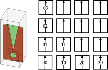
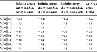
Consider the calculation of S[00][mn] for a rectangular array of slot antennas. The unit cell is pictured in Fig. 8. Part of the results of a convergence study for computation of the array element couplings are shown in Table 1. The coupling quantities computed are identified in column 1 of the table and the relative positions of the reference and secondary element for these couplings are shown in Fig. 8.
Unit cell for slot array and element locations for coupling results. Length and opening of the slot taper are 0.7λ 0 and 0.25λ 0, substrate is 0.045λ 0 thick with ɛ r = 2.2 and spacing is 0.37λ 0.

Passive coupling magnitude (dB) infinite array versus DDM.

Three sets of S FF(u, v) data were computed, one with spacing Δu = 0.1λ/a, Δv = 0.1λ/b, one with Δu = 0.05 λ/a, Δv = 0.05 λ/b, and the third with Δu = 0.025λ/a, Δv = 0.025λ/b. Since exact evaluation of the integral in (13) requires (Nyquist sampling) Δu < (1/2 M)λ/a and Δv < (1/2 N)λ/b the two sample spacings correspond to an assumption that coupling is negligible beyond spacings of 5, 10, and 20 elements apart, respectively.
The last column of data in Table 1 is generated as central element couplings for a 21 × 21 array analyzed using the DDM method. This size was selected with the expectation that couplings between the central elements would effectively equal that of an infinite array. The complete set of table data demonstrates convergence of the infinite array results to the DDM result as the sampling interval in u and v is reduced.
VI. CONCLUSION
In this paper, we have discussed two different methods for array analysis. Both are fundamentally based on the finite-element method, but very different approaches are taken. The first method is an optimized implementation of the classical infinite array model and the extraction of array performance from finite-element solutions of this model was discussed. A second approach is based on the DDM and its ability to harness the power of multiple CPUs to analyze entire finite arrays was discussed. Results from the two methods were compared and the differences ascribed to arise from the fundamental model assumptions of infinite versus finite array.
Finally, having looked at array simulation from the standpoint of analyzing a given configuration, we may also consider the issue of array synthesis, in other words the viewpoint of a design engineer tasked to design an array to a set of specifications. A natural approach is to create and optimize an initial design using a fast tool employing an idealized model. Having established the candidate design its performance may then be accurately verified for selected scenarios using the precise model. In particular, areas of concern predicted by the fast model may be assessed for their true impact.
Based on these considerations, we conclude by proposing the following design flow for a regular array of large order:
(1) Design the array lattice geometry and the radiating element in the infinite array environment using finite-element analysis of the unit cell as discussed above.
(2) Optimize the composite array pattern by varying element excitations in an array factor combined with the AEP determined in step (1).
(3) Simulate the finite array using the DDM for selected scan angles and excitations. Based on these results, possibly modify edge treatment or the design of the radiating elements near the edge of the array.
(4) Complete the array characterization by computing the passive coupling matrix for the finite array.
 John B. Manges obtained his Ph.D. in electrical engineering from Carnegie Mellon University in 1998. He has worked for Lockheed Martin (formerly General Electric Space Division), Ansoft Corporation, and Ansys Inc. Currently, he is an adjunct professor at Point Park University, Pittsburgh, PA. His interests include computational and applied electromagnetics.
 John W. Silvestro obtained his Ph.D. in electrical engineering from Case Western Reserve University in 1986. He worked at the ElectroScience Lab and Clemson University prior to joining Ansys Inc. (formerly Ansoft Corporation) where he is currently a Lead Product Engineer.
 Kezhong Zhao obtained his Ph.D. in electrical engineering from The Ohio State University in 2007. He is currently a Lead Research and Development Engineer at Ansys Inc. His interests include all aspects of computational electromagnetics.