





1. Introduction
The introduction of a viscous liquid within the narrow gap between two moving bodies prevents solid–solid contact, reduces friction, minimises wear and allows precise motion control; a process known as lubrication. Lubrication has played a pivotal role in major engineering milestones, from revolutionising the transportation of heavy objects on wooden sledges in ancient Egypt (Dowson Reference Dowson1998) to the efficient and reliable functioning of bearings in applications on many scales ranging up to the huge rolling bearings in today's wind turbines. The underlying hydrodynamic framework of fluid flow in thin gaps is in fact relevant to a range of phenomena across different length scales: motion of drops/bubbles in microfluidic devices (Bretherton Reference Bretherton1961; Byun Reference Byun2013), moving blood cells in capillaries (Fitz-Gerald Reference Fitz-Gerald1969; Secomb et al. Reference Secomb, Skalak, Özkaya and Gross1986), biomechanics of synovial joints (Hou et al. Reference Hou, Mow, Lai and Holmes1992) and the low friction of hydrogels (Cuccia et al. Reference Cuccia, Pothineni, Wu, Méndez Harper and Burton2020; Porte, Cann & Masen Reference Porte, Cann and Masen2020) to name a few. However, in most of the engineering applications as well as natural systems, one or both of the moving boundaries are deformable. As a result, lubrication flow is coupled to elasticity through the non-local soft lubrication equations.
Since the realisation of the essential coupling between deformation and flow for film formation, the study of elasto-hydrodynamic lubrication in engineering (tribology) has been established as a separate field of research. Its importance has only increased with the current need for reduced material and lubricant in view of sustainability demands. More complex time-varying and extreme operating conditions, such as higher loads and higher temperatures, lead to increased deformation and thinner films, which calls for a better understanding and improved prediction capability for engineering and design. Only in very specific asymptotic cases can analytic solutions be derived, and numerical solution is often needed. Pioneering work was done by Dowson & Higginson (Reference Dowson and Higginson1959, Reference Dowson and Higginson1966) and Hamrock & Dowson (Reference Hamrock and Dowson1977), where the complexity of the interaction between deformation and flow led to numerical stability problems at large deformations. Faster computers and improved numerical algorithms (Venner & Lubrecht Reference Venner and Lubrecht2000; Hamrock, Schmid & Jacobson Reference Hamrock, Schmid and Jacobson2004) allowed the study of realistic problems related to roller bearings, gears, cam followers and seals. Many studies aimed at the derivation of empirical formulas for film thickness prediction under steady conditions from the numerical solutions. Experimental validation was obtained from the further development of optical interferometry based techniques (Gohar & Cameron Reference Gohar and Cameron1963; Cann, Spikes & Hutchinson Reference Cann, Spikes and Hutchinson1996). At present, complex cases of contact geometries with time-varying loading conditions, roughness moving through the contact, contacts with very limited lubrication supply, grease lubricated contacts and coated surfaces are considered, see Wang & Zhu (Reference Wang and Zhu2019). In spite of the plethora of problems studied and results presented, the fundamental understanding of the physical phenomena and the appropriate scaling laws have developed only relatively slowly. A recent overview is given by Greenwood (Reference Greenwood2020).
A key feature of soft lubrication is the emergence of a non-inertial lift force, which facilitates lubrication by maintaining the gap between the moving surfaces (Sekimoto & Leibler Reference Sekimoto and Leibler1993; Skotheim & Mahadevan Reference Skotheim and Mahadevan2004). For micron sized particles flowing in a channel with soft walls, this force causes radial migration of particles (Davies et al. Reference Davies, Débarre, El Amri, Verdier, Richter and Bureau2018) and promotes particle sorting in microfluidic devices (Geislinger & Franke Reference Geislinger and Franke2014). A precise measurement of this elastohydrodynamic force can function as a contact-free tool to probe the local rheology of soft materials (Leroy et al. Reference Leroy, Steinberger, Cottin-Bizonne, Restagno, Léger and Charlaix2012; Wang, Dhong & Frechette Reference Wang, Dhong and Frechette2015). For sufficiently soft elastomers, this force is strong enough to sustain the weight of millimetre sized metal cylinders which slide along a deformable wall (Saintyves et al. Reference Saintyves, Jules, Salez and Mahadevan2016), and may result in intricate trajectories (Salez & Mahadevan Reference Salez and Mahadevan2015; Rallabandi et al. Reference Rallabandi, Saintyves, Jules, Salez, Schönecker, Mahadevan and Stone2017).
Naturally, it is of fundamental interest to explain how the gap thickness evolves from the coupling between fluid pressure and elastic deformation. The answer depends on details of the physical limit under consideration: Since deformation of a soft layer crucially depends on the geometry, and boundary conditions at the free surface, scaling laws relating the lift force to the lubrication layer are very different in different physical limits. Indeed, recent microfluidic experiments involving polymer brushes, cross-linked elastomers and ionic microgels as soft boundaries have probed elastohydrodynamic interactions in a few different limits, and experimentally found very distinct scaling laws (Davies et al. Reference Davies, Débarre, El Amri, Verdier, Richter and Bureau2018; Vialar et al. Reference Vialar, Merzeau, Giasson and Drummond2019; Zhang et al. Reference Zhang, Bertin, Arshad, Raphaël, Salez and Maali2020).
Specifically, the elastic layer can either be thick or thin, the material can be compressible or incompressible, while the elastic deformation can be large or small compared to the lubricant thickness. A well-studied limit is when the soft layer is thin and compressible, so that deformation is proportional to the local pressure, while assuming deformations to be small (Skotheim & Mahadevan Reference Skotheim and Mahadevan2005; Urzay, Llewellyn Smith & Glover Reference Urzay, Llewellyn Smith and Glover2007; Salez & Mahadevan Reference Salez and Mahadevan2015). This allows for a perturbative approach to solve the coupled elastohydrodynamic equations. However, most of the soft materials like elastomers and hydrogels are incompressible, and their response is described by non-local integral equations. Furthermore, if particles are squeezed past a soft layer, a Hertz-like contact forms, where deformation is large as compared to the gap thickness. In this case, the effect of lubrication is primarily dominant within a narrow boundary layer at inlet/outlet regions near the contact edges (Bissett Reference Bissett1989; Snoeijer, Eggers & Venner Reference Snoeijer, Eggers and Venner2013). This lubricated Hertzian limit is not only relevant for classical tribological applications, but also plays a role in soft matter systems such as the slippage of soft microgel pastes (Meeker, Bonnecaze & Cloitre Reference Meeker, Bonnecaze and Cloitre2004). Naturally, different scaling laws become relevant in these various limits, but an overview of how these different cases emerge – and when these are applicable – is still lacking.
Here, we present a unified overview of different regimes of soft lubrication. Our asymptotic analysis will focus on several important cases that were not considered previously, most notably the lubricated Hertz-like limit for cylinders on thin elastic layers on a rigid substrate. We also explore the transition to the small deformation limit, using numerical simulations. The paper is organised as follows. In § 2, we develop the theoretical and numerical framework and discuss the numerous length scales of the problem. Here, we emphasise how the relative magnitudes of these length scales determine the different asymptotic regimes of soft lubrication. The main focus of the analysis will be dedicated to the case of thin, compressible layers, in the regime of large deformation, which is addressed in § 3. This case is solved analytically through similarity solutions, by which we obtain the corresponding scaling laws. In the final § 4 this is complemented by the results for thin incompressible layers. Hence, we provide a complete overview of all regimes, summarised in a table in the concluding section, and discuss experimental consequences.
2. Framework
2.1. Problem formulation
We consider the two-dimensional problem of a rigid cylinder moving at constant velocity parallel to a deformable substrate, as sketched in figure 1. Here, we consider the translation of the cylinder, but we remark that the analysis is identical for the case that the cylinder is rotating (Pandey et al. Reference Pandey, Karpitschka, Venner and Snoeijer2016).
Schematic representation of a lubricated contact with a thin, compressible elastic layer, showing the relevant length scales of the problem: elastic layer thickness  $d$, contact size
 $a$, the fluid film thickness
 $h(x)$ and the elastic deformation
 $u(x)$ defined in the downward direction. One of the edges has been magnified to show the boundary layer width
 $\ell$, over which lubrication forces smooth out the elastic deformation.

Importantly, the analysis is organised in terms of the length scales that appear in the problem (figure 1). The hierarchy of the length scales is a crucial aspect of the lubrication problem, as the relative sizes of these lengths determine the asymptotic limit. Hence, the organisation of length scales will determine the scaling laws that relate load and velocity to the thickness of the lubrication layer.
A first aspect of the length scales is that we assume the cylinder radius,  $R$, to be much larger than the width of the contact zone,
 $a$, so that the shape can locally be approximated as a parabola. The lubricant layer thickness,
 $h(x)$, and the elastic deformation,
 $u(x)$, are then related by (figure 1)
 \begin{equation} h(x)-\frac{x^2}{2R}+c=u(x). \end{equation}
Here,  $c\equiv u(0)-h(0)$ is the indentation of the bottom of the cylinder, measured with respect to the undeformed elastic substrate. Another obvious length scale is the thickness
 $d$ of the elastic layer. Finally, we anticipate the emergence of a dynamic length scale
 $\ell$, sketched in the inset of figure 1, which acts as a narrow boundary layer at the edges of the contact (Snoeijer et al. Reference Snoeijer, Eggers and Venner2013). We will find that the relative magnitudes of
 $a,d,\ell , u$ and the compressibility of the elastic layer (quantified by the Poisson ratio
 $\nu$), will determine how the lubricant layer
 $h$ scales with the sliding velocity. We remark that, apart from
 $d$ and R, none of these lengths are known a priori, but follow from a consistent analysis of the problem.
Now that the geometry is in place, we can turn to the mechanical equations. We start with the flow of liquid within the narrow gap, which is described by the Stokes equation,  $\boldsymbol {\nabla } p = \eta \nabla ^2 \boldsymbol {v}$, where
 $p$ is pressure,
 $\eta$ is viscosity and
 $\boldsymbol {v}$ is the velocity field. We consider a reference system where the cylinder is stationary, and the substrate moves with a velocity
 $V$ to the right. Since both the film thickness and its gradient are small compared to the width of the contact, using no-slip boundary conditions, the velocity profile within the gap can be written in the lubrication limit,
 \begin{equation} v_x(x,z)=\frac{1}{2\eta}\frac{\partial p}{\partial x}[(z-u)^2+(z-u)h]+\left[1+\frac{z-u}{h}\right]V.\end{equation}
Incompressibility of the liquid requires that, at steady state, the flux  $Q=\int ^{u}_{u-h}v_x\, \textrm {d} z$ remains constant. As a result, integration of (2.2) gives the Reynolds equation (Reynolds Reference Reynolds1886),
 \begin{equation} \frac{\partial p}{\partial x}=6V\eta\frac{h-h^*}{h^3}, \end{equation}
where  $h^{\ast }=2Q/V$.
Next, we couple the pressure  $p(x)$ to the elastic deformation
 $u(x)$ of the solid. This is most conveniently done by transforming the problem to the Fourier domain (
 $\tilde {f}(q)=\int _{-\infty }^{\infty }f(x)\, \textrm {e}^{-\textrm {i}qx}\ {\textrm {d} x}$;
 $f(x)=\int _{-\infty }^{\infty }\tilde {f}(q)\, \textrm {e}^{\textrm {i}qx}\ ({\textrm {d} q}/{2{\rm \pi} })$). Namely, the elastic deformation of the substrate in Fourier domain is given by
 \begin{equation} \tilde{u}(q)={\mathcal{K}}(q)\tilde{p}(q), \end{equation}
where the Green's function  ${\mathcal {K}}(q)$ reads (Hannah Reference Hannah1951; Wang & Zhu Reference Wang and Zhu2019),
 \begin{equation} {\mathcal{K}}(q)=\frac{(1-\nu)}{Gq}\left[\frac{(3-4\nu)\sinh(2qd)-2qd}{(3-4\nu) \cosh(2qd)+2(qd)^2+5-12\nu+8\nu^2}\right]. \end{equation}
In this expression  $\nu$ is the Poisson ratio,
 $G$ is the shear modulus while
 $d$ is the layer thickness. For a given pressure, the backward transform to
 $u(x)$ is to be performed numerically. However, the above kernel can be simplified for various limiting cases, leading to analytical expressions for
 $u(x)$ in real space. We distinguish between two limits defined by the quantity
 $qd$, the ratio of the substrate thickness to the typical wavelength
 $1/q$ of the deformation. In the short-wavelength limit (
 $qd\gg 1$) the substrate's response locally reduces to that of an elastic half-space
 ${\mathcal {K}}(q)\sim |q|^{-1}$. In the opposite limit of large wavelength or a thin elastic layer (
 $qd\ll 1$),
 ${\mathcal {K}}(q)$ simplifies to different forms, respectively, for incompressible (
 $\nu =1/2$) and compressible (
 $\nu \neq 1/2$) materials. These results, along with the corresponding deformations, are summarised in table 1. The main focus of the calculations will be on the thin, compressible layers.
Overview of asymptotes for the Fourier space Green's function  ${\mathcal {K}}(q)$, given in (2.5). The two columns give the expansions of the Green's function and the corresponding pressure-deformation relations in real space.

The analysis can be closed by either imposing a vertical load exerted on the cylinder, or equivalently by fixing its vertical position. In our calculations we will impose the total vertical force  $L$, expressed in terms of the fluid pressure,
 \begin{equation} L=\int_{-\infty}^{\infty}p(x)\, \textrm{d} x. \end{equation}
The problem is defined by the system of three equations, ((2.1), (2.3) and (2.4)), which describe the three unknown fields  $h(x)$,
 $p(x)$ and
 $u(x)$. Furthermore, the constraint (2.6) enables us to find the vertical position
 $c$ of the cylinder. Combined with the boundary conditions
 $p(\pm \infty )=0$ and
 $u(\pm \infty )=0$, the problem is fully defined.
2.2. Regimes
Since our goal is to identify and describe the various limits of the elastohydrodynamic lubrication problem, the relevant length scales need to be carefully compared. These length scales, as defined in figure 1, are given by the contact size  $a$, the elastic layer thickness
 $d$, the boundary layer width
 $\ell$, the typical surface displacement
 $u_0$ and the sought-after lubricant thickness
 $h_0$. The reader can already consult table 2 for a complete overview of the various regimes.
Scaling laws for the film thickness at the centre of a cylinder, denoted  $h_0$, in the various regimes of soft lubrication. The limits are expressed in terms of length scales, as defined in figure 1. Previously available results have been indicated by the corresponding reference. Results without a reference have been derived in the present manuscript.

Small versus large deformations. Two key limits of the problem come from the comparison between the deformation  $u_0$ and the fluid film thickness
 $h_0$. When the sliding velocity of the cylinder is high, the cylinder experiences a strong upward force due to viscous stresses that separates it from the substrate. This gives the small deformation limit, where
 $h_0\gg u_0$ (Skotheim & Mahadevan Reference Skotheim and Mahadevan2005; Pandey et al. Reference Pandey, Karpitschka, Venner and Snoeijer2016). By contrast, for relatively low sliding velocity, the cylinder indents the substrate with only a thin layer of fluid in between the two, so that
 $h_0\ll u_0$. This is what will be referred to as the large deformation limit (Bissett Reference Bissett1989; Snoeijer et al. Reference Snoeijer, Eggers and Venner2013); we remark that, since typical deformations compared to the layer thickness remain small, the typical strains remain small as well, so that we still work in the context of linear elasticity.
Short versus long wavelengths. In the large deformation limit, a narrow lubrication boundary layer develops at the edge of the contact which regularises the jump in pressure gradient caused by elasticity. Comparing the width of this boundary layer  $\ell$ to the substrate thickness
 $d$, we can further distinguish two limits in the regime of large deformations. When
 $\ell \gg d$, the elastic problem is in the long-wavelength limit, in which the thin-layer approximation (
 $qd\ll 1$) is valid over the full width of the contact. In the short-wavelength limit (
 $\ell \ll d$), the thin elastic layer approximation does not hold at the edge of the contact, and the substrate locally responds like a half-space (
 $qd\gg 1$) within the boundary layer.
Compressible versus incompressible elastic layers. For each of the three above mentioned limits, one can choose a suitable response function given in table 1. For a comparatively thin layer,  $d\ll \ell$, one needs to make an additional distinction between a compressible and an incompressible material. This distinction is made since the leading-order term of the Taylor expansion of the kernel scales with
 $(1-2\nu )$, which vanishes in the incompressible case (
 $\nu =\frac {1}{2}$), making the next-order term dominant.
In the rest of the paper, we develop solutions of the elastohydrodynamic equations and, in table 2 we summarise these solutions through the scaling laws for the different regimes discussed above.
2.3. Non-dimensionalisation
While various of the cases reported in table 2 are already available in the literature, we are not aware of any lubrication analysis of large deformations on thin elastic layers. Therefore, we will from now on consider lubricated contacts with thin elastic coatings, and we primarily focus on the case of compressible layers. We introduce dimensionless variables that are suitable for this specific case (in the long-wave limit of the elastic deformation), and identify the single dimensionless number that governs the solution.
We consider the geometric relation (2.1) along with the deformation on thin compressible layers as given in table 1. Combining these two equations we get,
 \begin{equation} h(x)+c-\frac{x^2}{2R}=\frac{d(1-2\nu)}{2G (1-\nu)}p(x). \end{equation}
The small deformation limit has been solved before in Skotheim & Mahadevan (Reference Skotheim and Mahadevan2005), but here we consider the opposite limit. To non-dimensionalise the above equation for this limit we introduce the following scales,
 \begin{equation} x=\bar x a, \quad h=\bar h u_0=\bar h \frac{a^2}{2R}, \quad p=\bar p\frac{3L}{4a} , \end{equation}
where variables with an overbar are dimensionless. From this, one infers a natural characteristic horizontal scale, the contact size  $a$, as
 \begin{equation} a=\left[\frac{3}{4}\frac{LdR(1-2\nu)}{G (1-\nu)}\right]^{1/3}, \end{equation}
so that (2.7) reduces to
 \begin{equation} \bar{p}(\bar{x})=\bar{h}(\bar{x})+\bar c-\bar{x}^2.\end{equation}
Here, we further introduced  $\bar c = c/u_0$, based on the natural vertical scale
 \begin{equation} u_0 = \frac{a^2}{2R} = \left[\frac{3}{2^{7/2}}\frac{Ld(1-2\nu)}{R^{1/2}G (1-\nu)}\right]^{2/3}. \end{equation}
Using the relation between pressure and deformation (2.10), we find that Reynolds equation (2.3) can be written as
 \begin{equation} \frac{\partial \bar{h}}{\partial \bar{x}}-2\bar{x}=\lambda\frac{\bar{h}-\bar{h}^*}{\bar{h}^3}, \end{equation}
which contains the single dimensionless parameter of the problem,
 \begin{equation} \lambda=32\frac{V\eta}{L}\frac{R^2}{a^2}. \end{equation}
This parameter can be interpreted as the dimensionless velocity. The lubrication problem for a compressible elastic layer in the long-wave limit, is thus described by a first-order ordinary differential equation (ODE) for the flowing thickness  $\bar h(\bar x)$, given by (2.12). Note, however, that there are two boundary conditions to be imposed, namely the pressure must vanish at
 $\bar x = \pm \infty$, which can be expressed in terms of
 $\bar h$ using (2.10). The two boundary conditions for the first-order ODE (2.12) can indeed be satisfied by tuning the value of
 $\bar h^*$. In addition, the coefficient
 $\bar c$ must be tuned such that
 \begin{equation} \int_{-\infty}^{\infty}\bar{p}(\bar{x})\, \textrm{d}\bar{x}=\frac{4}{3}, \end{equation}
in order to impose the desired value of the load.
2.4. Numerical methods
To confirm the analytical results and to assess the cross-over between the asymptotic regimes, we employ two numerical methods. The first method is numerically solving (2.12) in Wolfram Mathematica, along with the corresponding boundary conditions and constraints. We use a shooting method for a range of values for  $\bar c$, finding the pair of
 $\bar h^*$ and
 $\lambda$ that allows us to satisfy the boundary conditions,
 $\bar p(\bar x\to \pm \infty )=0$ and
 $\int ^\infty _{-\infty } \bar p(\bar x)\, \textrm {d} \bar x = \tfrac {4}{3}$. Typical examples are given in figure 3. These accurately resolve the problem as long as the solution is self-consistent with the long-wave expansion.
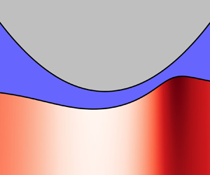
However, we will find that in the limit of very small  $\lambda$, the obtained solution is no longer consistent with the long-wave expansion of the elastic solid that underlies (2.12); we remark that the long-wave approximation for the liquid is satisfied for all cases considered. In this case, we turn to finite element simulations (FEM), where the two-dimensional plane strain problem is implemented using the library oomph-lib (Heil & Hazel Reference Heil and Hazel2006). A typical example of the numerical simulation is shown in figure 2. The compressible elastic layer is simulated by a nonlinear solid model using the neo-Hookean constitutive law with a Poisson ratio of
 $\nu =0.3$. Since the strains in this problem always remain small, the simulations reduce to linear elasticity and the choice of the nonlinear rheology does not influence the result. The domain has a width
 $W=10^5\ u_0$ (
 $|x| \leq W/2$) and height
 $d=30\ u_0$, and consists of refinable quad elements. The cylinder has a radius of
 $R=10^6\ u_0$, making for a contact size of
 $a\simeq 1.4\times 10^3\ u_0$. The elements in the adaptive mesh are locally refined down to a minimum size of
 ${\rm \Delta} x=5.2\times 10^{-6} u_0$, well below the smallest length scale, the boundary layer (
 $\ell \sim \lambda ^{2/5}$), at the lowest
 $\lambda$ value used. The fluid pressure is imposed on the top boundary of the elastic layer using surface elements that simulate the Reynolds equation (2.3). The pressure in the fluid is constrained to zero at both sides of the domain and the nodes at the bottom of the elastic layer are fixed in both the vertical and horizontal direction. The nodes on both the left and right sides of the layer are fixed only in the horizontal direction and are subject to a no-shear condition in the vertical direction.
Typical lubricated contact obtained in finite element simulations. The colour map indicates the normalised trace of the strains in the thin compressible elastic layer. This result is obtained at an intermediate value of the sliding velocity, where the elastic deformation is comparable to the minimal lubrication thickness. The parameters in this simulation are  $\lambda = 6.4$ and
 $R=10^3\ u_0$, with all other parameters equal to those listed in § 2.4.

3. Thin compressible layer
In this section, we present results for the lubricated contact with a thin compressible elastic substrate. We first illustrate the emergence of three distinct asymptotic regimes by presenting numerical results, both from the long-wave expansion of (2.12) and based on the finite element simulations. Then, we turn to a detailed asymptotic analysis of the two regimes that involve large deformations, respectively corresponding to long and short wavelengths.
3.1. Numerical results
Figure 3 reports a number of film thickness profiles  $\bar h=h/u_0$ for lubricated contacts, for various values of the dimensionless sliding velocity
 $\lambda$ as defined by (2.13). The results presented in the figure were obtained from numerical integration of (2.12), and also include the ‘dry’ solution, corresponding to the case
 $\lambda =0$ where there is no motion. The profiles in figure 3 clearly reveal a qualitative change in the shape of the contact upon increasing the velocity. At small
 $\lambda$, the profiles exhibit a large elastic deformation where the cylinder pushes deep into the soft coating. The liquid profile closely resembles that of the ‘dry’ solution, except near the inlet (
 $\bar x=-1$) and the outlet (
 $\bar x=1$) regions where the effect of lubrication is prominent. At these two edges of the contact region, we encounter a narrow boundary layer of width
 $\ell$, as sketched in the inset of figure 1. These boundary layers will be analysed in detail below, as they are essential for computing the entrained liquid thickness. At large
 $\lambda$, the liquid thickness becomes very large and the profile is smooth over the entire horizontal range. Gradually, the gap approaches the shape of the rigid cylinder, since the elastic deformation of the coating becomes small in comparison to the lubricant thickness.
Numerical film thickness profiles  $\bar h = h/u_0$ as a function of
 $\bar x = x/a$, for the case of a compressible thin elastic layer. Lubricated contacts correspond to
 $\lambda >0$, and are obtained from numerical integration of (2.12). The case
 $\lambda =0$ is a ‘dry’ contact, given by the analytical expression of (3.1b).

We now take a closer look at the deformations over the full range of  $\lambda$ for the long-wave description and the finite element simulations – both pertaining to thin compressible coatings. In figure 4 we therefore plot the fluid layer thickness at the centre
 $\bar h_0=h_0/u_0$, as a function of the dimensionless velocity
 $\lambda$. The layer thickness is furthermore compensated by the scaling
 $\lambda ^{1/2}$ that will be derived analytically below. From the figure we can see that for values of
 $\lambda \gtrsim 10^{-4}$ the two different numerical methods agree with one another – confirming the validity of the long-wave expansion at moderate and large values of
 $\lambda$. The long-wave data (represented as stars), exhibit two asymptotic regimes:
 $h_0 \sim \lambda ^{1/2}$ (dashed line) and
 $h_0 \sim \lambda ^{4/7}$ (dash-dotted line). However, it is also clear that, at the smallest
 $\lambda$, the long-wave description breaks down, since the numerical solution of the true elastohydrodynamic problem (represented by triangles) gives yet another scaling law
 $h_0 \sim \lambda ^{3/5}$ (solid line). We will see below that this limit emerges when the width of the boundary layer
 $\ell$ becomes comparable to the thickness of the coating
 $d$, so that the long-wave description is no longer justified.
Lubrication thickness for thin compressible coatings, combining numerical (§ 2.4) and analytical (table 2, middle row) results. The graph reports the thickness of the fluid film at the centre of the lubricated contact,  $h_0$, as a function of the dimensionless sliding velocity
 $\lambda$. The dimensionless thickness
 $\bar h=h_0/u_0$ is compensated by the intermediate asymptote
 $\bar h_0 \sim \lambda ^{1/2}$ (dashed line). Distinct asymptotic limits are observed at small
 $\lambda$ (solid line,
 $\bar h_0 \sim \lambda ^{3/5}$) and large
 $\lambda$ (dash-dotted line,
 $\bar h_0 \sim \lambda ^{4/7}$). We remark that each of the indicated asymptotes are derived analytically (including the prefactors).

In summary, we thus find the emergence of 3 regimes at small, intermediate and large values of  $\lambda$. The analysis for large
 $\lambda$ has already been performed by Skotheim & Mahadevan (Reference Skotheim and Mahadevan2004, Reference Skotheim and Mahadevan2005). Hence, below we derive the intermediate asymptotics (using the long-wave description at small
 $\lambda$), and the ultimate asymptotics
 $\lambda \ll 1$ based on the short-wave description.
3.2. Long-wavelength elasticity: dry solution
Before turning to the dynamical case, we first provide the dry (static) solution of the long-wave approximation, given by (2.10). Formally, this corresponds to  $\lambda =0$, for which no flow takes place. This dry solution therefore corresponds to the situation where the pressure vanishes outside the contact region,
 $\bar {p}=0$ for
 $|\bar {x}|>1$, and the gap thickness vanishes within the contact,
 $\bar {h}=0$ for
 $|\bar x|<1$. The corresponding dry solution to (2.10) reads,
 \begin{gather} \bar{p}=(1-\bar{x}^2)\varTheta(1-\bar{x}^2), \end{gather}
 \begin{gather}\bar{h}=(\bar{x}^2-1)\varTheta(\bar{x}^2-1), \end{gather}
where  $\varTheta$ is the Heaviside step function.
Expanding these near the edges of the contact, located at  $\bar {x}=\mp 1$, we find
 \begin{equation} \bar{p}\simeq{\pm} 2(\bar{x}\pm 1) \quad \bar{h}\simeq{\mp} 2(\bar{x}\pm 1). \end{equation}
This linear behaviour of the gap can be observed in figure 3, at the edge of the dry solution. This asymptote is of particular importance to the dynamical case at small speed, where  $\lambda$ is small but non-zero. In that limit, lubrication effects quickly decay outside the narrow boundary layers near the edge of the contact, so that the static solution is approached. Specifically, the boundary layer solutions must therefore be matched to the linear asymptote given by (3.2a,b).
3.3. Long-wavelength elasticity: lubricated solution
Once the cylinder starts to move, a thin film of liquid is entrained within the contact region and in particular, the left–right symmetry of the deformation is broken (figure 3). Liquid is squeezed into the contact at the inlet, at  $\bar x=-1$, and is pushed out at the outlet, at
 $\bar x=1$. To analyse the behaviour of (2.12) at the two lubricated edges, we look for similarity solutions of the form
 \begin{equation} \bar{h}=\lambda^\alpha H(\xi) \quad \xi=(\bar{x}\pm 1)\lambda^{-\beta}. \end{equation}
Here, the  $+$ sign refers to the inlet and
 $-$ to the outlet. In terms of the similarity variables, the matching condition (3.2a,b) becomes
 $H(\xi ) \simeq \mp 2\xi$ for
 $\xi \rightarrow \mp \infty$. This
 $\lambda$-independent far-field condition requires that
 $\alpha =\beta$. The Reynolds lubrication (2.12), written in terms of the above similarity variables, gives
 \begin{equation} \lambda^{\alpha-\beta}\frac{\partial H}{\partial \xi}\pm 2-2\lambda^\beta\xi=\lambda^{1-2\alpha}\frac{H-H^*}{H^3}. \end{equation}
Anticipating that  $\beta >0$, i.e. thin boundary layers for
 $\lambda \ll 1$, the term
 $\sim \lambda ^{\beta }$ is subdominant with respect to the constant. For the remaining equation to be independent of
 $\lambda$, we need
 $\alpha -\beta =1-2\alpha$. Combined with the matching condition of
 $\alpha =\beta$, we thus find the exponents
 \begin{equation} \alpha=\beta=\tfrac{1}{2}, \end{equation}
while (3.4) reduces to
 \begin{equation} \frac{\partial H}{\partial \xi}\pm 2=\frac{H-H^*}{H^3}. \end{equation}
The solution to this equation must match to  $H(\xi \rightarrow \mp \infty ) = \mp 2\xi$, as discussed before. Furthermore, the gap should converge to a film of constant thickness inside the contact, leading to
 $({\partial H}/{\partial \xi })(\xi \rightarrow \pm \infty ) = 0$.
3.3.1. Inlet region
At the inlet (3.6) becomes
 \begin{equation} \frac{\partial H}{\partial \xi}=\frac{H-H^*-2 H^3}{H^3}. \end{equation}
We first wish to find the constant thickness  $H_0$ that is approached when entering the central zone of the contact (corresponding to
 $\xi \rightarrow \infty$). Interestingly,
 $H_0$ is not simply equal to
 $H^{\ast }$, but is to be determined from the equation
 $H_0-H^*-2 H_0^3=0$. For this film thickness to take on a positive real value, it is required that
 $H^* \geq \frac {1}{9}\sqrt {6}$. However, under this condition there are still two possible solution branches of
 $H_0$ for a given
 $H^*$.
For the selection of the relevant  $H_0$, we now investigate whether the solution indeed approaches
 $H_0$ for
 $\xi \rightarrow \infty$. We therefore linearise (3.7) using
 $H=H_0 + H_1(\xi )$, which gives
 \begin{equation} \frac{\partial H_1}{\partial \xi}=\frac{1-6 H_0^2}{H_0^3} H_1. \end{equation}
This shows that the solution exponentially approaches a constant film thickness when  $H_0 > \frac {1}{6}\sqrt {6}$. This condition selects the branch of acceptable
 $H_0$, which for a given value of
 $H^*$ indeed decays to a flat film below the contact. We need to separately consider the special case where
 $H_0 = \frac {1}{6}\sqrt {6}$ and
 $H^* = \frac {1}{9}\sqrt {6}$. In this case the similarity solution can even be found in closed form,
 \begin{equation} \xi ={-}\frac{1}{2}H + \frac{4}{9}H_0\ln\left(\frac{\frac{1}{2}H+H_0}{H+H_0}\right) + \frac{1}{36(H-H_0)}. \end{equation}
This solution exhibits an algebraic decay to the flat film of thickness  $H_0$ as
 $\xi \rightarrow \infty$, and therefore should also be considered.
It will turn out that, indeed, the special case of  $H_0 = \frac {1}{6}\sqrt {6}$ and
 $H^* = \frac {1}{9}\sqrt {6}$ provides the relevant solution for the lubrication problem. This will be shown by analysing the ‘central region’, as done below in § 3.3.3. Hence, the correct inlet thickness reads
 \begin{equation} H_\textrm{in} = \tfrac{1}{6}\sqrt{6} \approx 0.408, \end{equation}
while the corresponding value for  $H^*$ is given by
 \begin{equation} H^* = \tfrac{1}{9}\sqrt{6} \approx 0.272. \end{equation}
3.3.2. Outlet region
The similarity equation for the outlet differs from (3.7) only in the sign of the last term on the right-hand side,
 \begin{equation} \frac{\partial H}{\partial \xi}=\frac{H-H^*+2 H^3}{H^3}. \end{equation}
Anticipating that  $H^* = \frac {1}{9}\sqrt {6}$, we could find a lengthy closed form solution to (3.12) using Mathematica (not given here). Remarkably, the solution approaches a constant thickness
 $H_{out}$ as
 $\xi \rightarrow -\infty$ that turns out to be different from the inlet thickness
 $H_{in}$. Indeed, solving
 ${\partial H}/{\partial \xi }=0$ for
 $H^*=\frac {1}{9}\sqrt {6}$, one finds
 \begin{equation} H_{out} = \tfrac{1}{6}\sqrt{6}[(\sqrt{2}+1)^{{1}/{3}}-(\sqrt{2}-1)^{{1}/{3}}]\approx 0.243, \end{equation}
which is significantly below  $H_{in}$. This means the liquid film cannot possibly be flat within the central region connecting the inlet and outlet, and we need to treat this region separately.
3.3.3. Central region
As just demonstrated, the constant film thicknesses at the inlet and outlet cannot be equal, these satisfy two different equations for the same value of  $H^*$. To find the variation in film thickness across the central zone, another similarity solution has to be introduced, namely,
 \begin{equation} \bar h=\lambda^{1/2} {\mathcal{H}}(\bar{x}). \end{equation}
Since this similarity solution does not scale the solution in horizontal direction, this equation is valid when 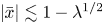 $|\bar {x}|\lesssim 1-\lambda ^{1/2}$, i.e. over the full width of the contact excluding the boundary layers. Substituting this into the lubrication (2.12) gives an algebraic equation for the film thickness,
 \begin{equation} {\mathcal{H}}- H^*+ 2\bar{x} {\mathcal{H}}^3=0,\quad \Longrightarrow \bar x = \frac{H^*- {\mathcal{H}}}{2{\mathcal{H}}^3}. \end{equation}
Since  $\mathcal {H}$ describes the central zone up to the boundary layers, (3.15) needs to cover the entire domain
 $-1 < \bar x < 1$. One verifies that this is only the case when
 $H^* \leq \frac {1}{9}\sqrt {6}$. This condition is exactly opposite to the requirement derived from the inlet solution, which only gives physical solutions for
 $H^* \geq \frac {1}{9}\sqrt {6}$. Hence, the only possibility for the central zone to connect inlet and outlet is when
 $H^* = \frac {1}{9}\sqrt {6}$, as anticipated above.
3.3.4. Summary and numerical validation
Figure 5 summarises the key results of this section. The panels (a-c) respectively report the similarity solutions for the narrow boundary layers at (a) the inlet, (c) the outlet and (b) the central region that connects the two. The symbols represent the analytical solutions derived above, and these are plotted along with scaled FEM numerical solutions (solid lines, for various  $\lambda$). An excellent agreement is observed in all three regions.
Fluid film thickness profiles at the (a) inlet, (b) central region and (c) outlet of a lubricated contact on a compressible thin layer in the long-wave limit. The solid lines represent rescaled FEM solutions for  $4.99 \times 10^{-4} \leq \lambda \leq 2.26\times 10^{-2}$, while the symbols denote the similarity solution derived in § 3.3. The solution in (b) is plotted over the full range
 $|\bar {x}|<1$, but is not valid in the region near the edge of the contact.

The similarity solution also provides the exact expression for the fluid film thickness  $h_0$. For this we evaluate (3.15) at
 $x=0$, which gives immediately that the (scaled) film thickness at the centre of the contact is equal to
 $H^* = \frac {1}{9}\sqrt {6}$. In dimensional form it gives
 \begin{equation} h_0= \frac{a^2}{2R} H^* \lambda^{1/2} = \left[\frac{2^{4}}{3^{7/2}}\sqrt{\frac{\eta^3 V^3}{G^2 L}}\frac{Rd(1-2\nu)}{1-\nu}\right]^{1/3}. \end{equation}
This result, including the theoretical prefactor, is used in figure 4 (dashed line), which shows that the numerical solutions of the long-wavelength approximation indeed converge towards the derived similarity solution. With respect to the full resolution of the elastohydrodynamic problem using finite elements, the solution (3.16) appears as an intermediate (long-wave) asymptote.
3.4. Short-wave elasticity: the ultimate asymptotics for  $\lambda \ll 1$

The numerical results obtained by finite element simulations, shown in figure 4, revealed that, at very small  $\lambda$, another limit develops. The reason for this is that the boundary layer width in the long-wave theory was found to scale as
 $\ell \sim \lambda ^{1/2}$, so that at sufficiently small
 $\lambda$ it becomes comparable to the thickness of the elastic layer – at which point the long-wavelength description becomes inconsistent. Hence, the ultimate small
 $\lambda$ asymptote involves the hierarchy of scales
 $\ell \ll d \ll a$, and requires the full kernel of (2.5). Below, we first consider the corresponding static problem, to identify the appropriate horizontal, vertical and pressure scales. Subsequently, in the next subsection, we use the dry solution to match the boundary layers.
3.4.1. Dry solution
In fact, even the static indentation problem with  $d \ll a$, already involves the full kernel (2.5). This problem goes back to Meijers (Reference Meijers1968), who considered the Hertz contact on layers of arbitrary thickness. On the scale of the contact width
 $a$, the static solution of the long-wavelength description, ((3.1a), (3.1b)), is perfectly valid when
 $d\ll a$. Near the edges, however, the linear behaviour of the pressure gives way to a square-root dependence, as is illustrated in figure 6(a). The reason for this is that near the edges, the elasticity is governed by the short-wavelength limit of the elastic kernel (2.5). Introducing
 $\zeta =x\pm a$, indicating the unscaled distance to the contact edge, this gives the elastic relation
 \begin{equation} h(\zeta)+c-\frac{(\zeta\mp a)^2}{2R}={-} \frac{1-\nu}{{\rm \pi} G}\int_{-\infty}^{\infty}\ln|\zeta-\zeta'|p(\zeta')\, \textrm{d} \zeta', \end{equation}
which combines (2.1) and the deformation from table 1 in the limit  $qd \gg 1$. It is well known that this equation gives
 \begin{equation} p \simeq A \sqrt{\pm \zeta}, \end{equation}
at the contact edge (Snoeijer et al. Reference Snoeijer, Eggers and Venner2013), where the scaling properties of  $A$ remain to be determined. This behaviour is indeed manifestly different from the linear behaviour obtained from the long-wave expansion (3.2a,b), which in terms of a dimensional scaling law can be written as
 \begin{equation} p \sim{\pm} \frac{L}{a^2} \zeta, \end{equation}
with  $a$ given by (2.9). To estimate the value of the constant
 $A$, we now use a matching of the two descriptions, as is depicted schematically in figure 6(a). This is done by equating (3.18) to (3.19) at a distance
 $|\zeta | \sim d$. This matching gives an expression for the parameter
 $A$,
 \begin{equation} A = A_p \left[\frac{G^2 L}{\sqrt{d} R^2} \frac{(1-\nu)^2}{(1-2\nu)^2}\right]^{1/3}, \end{equation}
where  $A_p$ is a (dimensionless) constant. The value of the constant is obtained from a numerical solution of the static dry contact problem, using the finite element method. We calculate the pressure profile of this contact – in the absence of lubrication effects – in accordance with the parameters in § 2.4. The result is given in figure 6(b), from which we deduce that
 $A_p\approx 1.33\pm 0.09$ by fitting (3.18) in the region where the pressure has converged to the short-wave approximation, i.e.
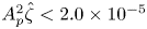 $A_p^2\hat {\zeta }<2.0\times 10^{-5}$.
(a) Schematic representation of the pressure profile of a static contact, on a thin compressible layer. The long-wave approximation (red dashed) breaks down near the edge of the contact, at a distance comparable to the thickness of the elastic layer (in this case  $d \sim 0.1 a$, where
 $d$ is the layer thickness and
 $a$ the contact width). (b) Pressure profile at the edge of a dry, static contact on a thin compressible layer, resolved using finite element simulations (symbols). The data are fitted with (3.18), shown as the solid line, from which we obtain the numerical constant
 $A_p\approx 1.33$ defined in (3.20).

Now that we know the behaviour of the static solution near the contact edge, we can identify the proper scalings for  $p$,
 $h$ and
 $\zeta$. This is important, since these will subsequently be used to describe the dynamic boundary layers. To establish the scalings, we first take two derivatives of (3.17), which gives
 \begin{equation} \frac{\partial^2 h(\zeta)}{\partial \zeta^2}=\frac{1}{R}-\frac{1-\nu}{{\rm \pi} G} \int_{-\infty}^{\infty}\frac{\partial p(\zeta')}{\partial \zeta'}\frac{1}{\zeta-\zeta'}\, \textrm{d} \zeta', \end{equation}
where we also performed an integration by parts. Demanding that the three terms in this equation are of the same order, while also respecting the scaling of  $A$ in ((3.18), (3.20)), we find the appropriate scalings to be
 \begin{align} p &= \frac{A_p^2}{2} \left[\frac{G L^2}{Rd} \frac{(1-\nu)^7}{(1-2\nu)^4}\right]^{1/3} \hat{p}, \\
\zeta &=\frac{A_p^2}{2} \left[\frac{L^2 R^2}{G^2 d} \frac{(1-\nu)^{10}}{(1-2\nu)^4}\right]^{1/3} \hat{\zeta}, \\
h &= \frac{A_p^4}{4}\left[\frac{L^4 R}{G^4 d^2} \frac{(1-\nu)^{20}}{(1-2\nu)^8}\right]^{1/3} \hat{h}.\end{align}
With this, the dimensionless equation describing the elasticity of the layer reads
 \begin{equation} \frac{\partial^2 \hat{h}}{\partial \hat{\zeta}^2}=1-\frac{1}{\rm \pi}\int_{-\infty}^{\infty} \frac{\partial \hat{p}(\hat{\zeta}')}{\partial
\hat{\zeta}}\frac{1}{|\hat{\zeta}-\hat{\zeta}'|} \, \textrm{d} \hat{\zeta}',
\end{equation}
while the asymptote of the static solution reduces to
 \begin{equation} \hat{p} \simeq \sqrt{\pm 2 \hat{\zeta}}. \end{equation}
3.4.2. Lubricated solution
We now turn to the dynamical case, by expressing the Reynolds equation (2.3) in the new variables of (3.22). This gives
 \begin{equation} \frac{\partial \hat{p}}{\partial \hat{\zeta}}=\lambda_s\frac{\hat{h}-\hat{h}^*}{\hat{h}^3}, \end{equation}
which is of the same form as before. However, owing to the new scaling, the parameter that gives the dimensionless velocity is different, and reads
 \begin{equation} \lambda_s = \frac{96}{A_p^8} \left[\frac{\eta^3 V^3 d^4 R G^5}{L^8} \frac{(1-2\nu)^{16}}{(1-\nu)^{37}}\right]^{1/3}. \end{equation}
The analysis of the boundary layer is now given by the system ((3.23), (3.25)), with matching condition (3.24). This reduced problem is strictly identical to that of the boundary layers on a half-space, as previously described by Snoeijer et al. (Reference Snoeijer, Eggers and Venner2013). Hence the solution is exactly the same, and gives a thickness  $\hat h \sim \lambda _s^{3/5}$, a boundary layer width
 $\hat \zeta \sim \lambda _s^{2/5}$, while the pressure
 $\hat p \sim \lambda _s^{1/5}$. For detailed derivations we refer to Snoeijer et al. (Reference Snoeijer, Eggers and Venner2013). Note, however, that in dimensional variables the result is different. In particular, we find for the dimensional flowing thickness
 \begin{align} h_0 &= 0.4467 \frac{A_p^4}{4} \left[\frac{L^4 R}{G^4 d^2} \frac{(1-\nu)^{20}}{(1-2\nu)^8}\right]^{1/3} \, \lambda_s^{3/5} \nonumber\\ &=\frac{1.7271}{A_p^{4/5}} \left[ \frac{d^2 R^8 \eta^9 V^9 }{G^5 L^4} \frac{(1-2\nu)^8}{(1-\nu)^{11}}\right]^{1/15}, \end{align}
where the numerical constant 0.4467 was determined in Snoeijer et al. (Reference Snoeijer, Eggers and Venner2013) by solving  $\hat h^*$ from the boundary layer problem, while we recall that
 $A_p\approx 1.33$. This result is given as the solid line in figure 4, and indeed accurately describes the ultimate
 $\lambda \ll 1$ asymptotics.
The structure of the boundary layers is further illustrated in figure 7. There, the similarity solutions from Snoeijer et al. (Reference Snoeijer, Eggers and Venner2013) are reproduced (symbols), and compared to the scaled FEM simulations at very small  $\lambda$. All curves indeed collapse, confirming the validity of the similarity analysis. Interestingly, for this case the thickness of the lubrication layers leaving the inlet and entering the outlet directly align. The central zone is therefore perfectly flat – this is to be contrasted with the result for the long-wave similarity solutions of figure 5, for which the inlet and outlet were connected by a non-trivial central region.
Fluid film thickness profiles at the (a) inlet and (b) outlet of a lubricated contact on a compressible thin layer in the short wave limit (i.e. the ultimate regime for  $\lambda \ll 1$). The solid line represents a rescaled FEM solution for
 $4.75 \times 10^{-7} \leq \lambda \leq 7.42\times 10^{-5}$, while the symbols show the similarity solutions by Snoeijer et al. (Reference Snoeijer, Eggers and Venner2013). These similarity solutions are shifted horizontally to align with the numerical solutions.

4. Discussion
The aim of this work is to present all scaling laws governing the movement of a cylinder over an elastic substrate in the presence of a fluid. Some of these scaling laws were derived previously in the literature, but focussing on separate regimes – importantly, the limiting cases of thin elastic layers with large deformations had not previously been considered. This important gap is filled in the present paper, thereby offering a complete and comprehensive overview.
Table 2 summarises both previous and our newly obtained results. All the different regimes of soft lubrication are organised in terms of the length scales  $d$ (thickness of the elastic coating),
 $a$ (size of the contact),
 $u_0$ (scale of elastic deformation) and
 $\ell$ (boundary layer width near the contact edges). In terms of experimental parameters, the table should be read as follows. For fixed material properties, magnitude of the applied load
 $L$ determines the typical size of the contact
 $a$. Hence, upon specifying the load one selects one of the rows of table 2, comparing the contact size to the elastic layer thickness. Then, at very small velocity
 $V$ one starts in the left column, where the flowing thickness
 $h_0 \ll u_0$, referring to the case of relatively large elastic deformation. Subsequently, upon increasing the velocity, the boundary layer
 $\ell$ and the lubrication film
 $h_0$ increase, and one progressively moves to the second and third columns, ultimately reaching the small deformation limit (
 $h_0 \gg u_0$).
There are a few important features in this table. At very small velocities (left column), the scaling  $h_0 \sim V^{3/5}$ is the same for all cases. In this case, the width of the boundary layers is the smallest scale in the system and thereby these exhibit a universal structure. Differences arise only from matching these boundary layers to different (static) outer solutions. On the contrary, at very large velocity (right column) the scaling laws always involve the combination
 $(\eta V)^2/L$. So, when working at a fixed separation distance instead of at fixed load, one finds the well-known scaling law for the lift force
 $L \sim (\eta V)^2$ (Sekimoto & Leibler Reference Sekimoto and Leibler1993; Skotheim & Mahadevan Reference Skotheim and Mahadevan2004; Greenwood Reference Greenwood2020). A key result of our analysis is the emergence of an intermediate asymptote,
 $h_0\sim V^{1/2}$ for the thin, compressible layer – closed form analytical solutions for this case are provided.
From an experimental perspective, it is of particular interest to consider the extension of the scaling laws in table 2 to three-dimensional spherical contacts. While the exact solutions are not valid for spherical contacts, the specific features listed in this paragraph do remain valid. For large deformation contacts on an elastic half-space Snoeijer et al. (Reference Snoeijer, Eggers and Venner2013) demonstrated the validity of  $h_0 \sim V^{3/5}$ in the three-dimensional situation. The reason for this is that the boundary layer remains small compared to the contact size, and the local problem is effectively two-dimensional. Note, however, that the scaling with elastic constants and the load changes in the three-dimensional case. For example, for the semi-infinitely thick layer, the relation between lift force (load) and velocity was predicted as
 $F \sim (\eta V)^{3/4}G^{1/4}$ (Snoeijer et al. Reference Snoeijer, Eggers and Venner2013). Indeed, this scaling law was recently recovered experimentally in Zhang et al. (Reference Zhang, Bertin, Arshad, Raphaël, Salez and Maali2020). We remark that the scaling
 $h_0 \sim V^{3/5}$ will be valid for the three-dimensional case for the entire left column of the table, and the same holds for
 $h_0\sim V^{1/2}$ in the middle column – the reason being that the boundary layers in these cases are always small compared to the contact size. Finally, for the small deformation contacts in the right column, Skotheim & Mahadevan (Reference Skotheim and Mahadevan2005) showed how the universality in the lift force
 $L \sim (\eta V)^2$, also for spherical contacts. This scaling in the small deformation limit was indeed observed experimentally for spherical contacts (Davies et al. Reference Davies, Débarre, El Amri, Verdier, Richter and Bureau2018; Vialar et al. Reference Vialar, Merzeau, Giasson and Drummond2019; Zhang et al. Reference Zhang, Bertin, Arshad, Raphaël, Salez and Maali2020). Note that when verifying the dependence on elastic modulus and thickness, care must be taken to select the correct limit (thin versus thick, compressible versus incompressible).
Another new result of our study is the scaling law for a thin incompressible layer subjected to large indentation. Leaving the details to appendix A, here, we discuss the key features of this limit. In the limit where the boundary layer represents the smallest scale,  $\ell \ll d$, the only change compared to the compressible case is in the static ‘dry’ solution, leading to different exponents of geometric and material parameters. However, the scaling
 $h_0 \sim V^{3/5}$ is robust. Next, we consider the intermediate range,
 $d\ll \ell \ll a$, where the small boundary layers are in between the coating thickness and the contact size. Interestingly, this case does not admit a consistent long-wave description, and therefore a proper intermediate asymptotic regime appears to be missing. The resulting long-wavelength ODE can be derived – unlike the compressible case, however, it does not admit solutions at small
 $\lambda$ that connect the inlet and the outlet region. For completeness, we show in figure 8 the numerical relation between the central thickness
 $h_0$ and the velocity
 $V$ obtained by finite element simulations. It very nicely confirms the scalings of the bottom row in table 2, corresponding to the small and large speed asymptotics for thin incompressible layers.
Lubrication thickness for thin incompressible coatings, combining numerical (§ 2.4) and analytical (table 2, middle row) results. The graph reports the thickness of the fluid film at the centre of the lubricated contact,  $h_0$, rescaled according to (A4) as a function of a dimensionless sliding velocity. The dimensionless sliding velocity uses
 $a_i$ as defined in (A3). Distinct asymptotic limits are observed at low velocity (solid line,
 $\bar h_0 \sim \lambda ^{3/5}$) and high velocity (dashed line,
 $\bar h_0 \sim \lambda ^{4/9}$). The prefactor of the high velocity asymptote is derived analytically, while for the low velocity asymptote the data were fitted by (A11), with
 $A_{i,p}\simeq 1.85$.

In conclusion, our study identifies key geometric parameters in the soft lubrication problem of compressible and incompressible elastic solids. From an experimental perspective, our results point out the importance of: (i) the ratio of elastic coating thickness to contact size, (ii) the Poisson ratio of the layer (compressible versus incompressible) and (iii) the ratio of elastic deformation over the lubricant thickness. When interpreting experiments, one must verify the relevant regime, with table 2 serving as a guide. Our unified framework also connects the two most studied limits of the problem: the lubricated Hertzian contact regime, relevant for many industrial applications, and the large separation (small deformation) regime, important in microfluidic and biological contexts. We anticipate the results presented here to have important implications beyond the realm of soft lubrication, e.g. in understanding the rheology of suspension flow in channels (Rosti, Ardekani & Brandt Reference Rosti, Ardekani and Brandt2019), size dependent migration of particles (Rallabandi et al. Reference Rallabandi, Oppenheimer, Zion and Stone2018), and direct measurement of interfacial rheology in soft matter systems (Garcia et al. Reference Garcia, Barraud, Picard, Giraud, Charlaix and Cross2016).
Acknowledgements
We thank T. Salez for numerous discussions on various limits of soft lubrications.
Funding
We acknowledge financial support from ERC (the European Research Council) Consolidator Grant No. 616918, and from NWO through VICI Grant No. 680-47-632.
Declaration of interest
The authors report no conflict of interest.
Appendix A. Thin incompressible layer, small velocity
The derivation of the dry contact between a cylinder on and an incompressible thin layer is similar to that of a compressible layer. The main difference lies in the elastic Green's function of table 1, which differs in the long-wave limit. Combined with (2.1), the elastic response gives
 \begin{equation} h(x) - \frac{x^2}{2R} + c= \frac{d^3}{3G}\frac{\partial^2 p}{\partial x^2}. \end{equation}
In principle, this relation can be combined with the Reynolds (2.3) to yield an ODE for  $h(x)$. It turns out, however, that this long-wave expansion does not admit solutions at small
 $\lambda$ that connect the inlet and the outlet region. Therefore, we only focus on the ultimate asymptotics at
 $\lambda \ll 1$, where the boundary layers width
 $\ell \ll d$ and are described by the short-wave kernel. The subsequent analysis now runs parallel to that of § 3.4. The boundary layers exhibit a universal structure, but the corresponding scales need to be identified from matching to the static solution (now, on thin incompressible layers). In particular, we know the asymptote to be of the form
 \begin{equation} p \simeq A_i \sqrt{\pm \zeta}, \end{equation}
where  $\zeta =x\pm \chi a_i$ is the distance from the edge, and we need to identify
 $A_i$ of the static solution.
For this, we proceed as in § 3.4. We first consider the static long-wave solution, from (A1), which gives the relevant horizontal length scale  $a_i$,
 \begin{equation} a_i=\left[\frac{5}{6\sqrt{3}}\frac{Ld^3R}{G}\right]^{1/5}. \end{equation}
We introduce the scalings,
 \begin{equation} p=\frac{5\sqrt{3}L}{16a_i} \bar{p}, \quad x=a_i \bar{x}, \quad h=\frac{a_i^2}{2R} \bar{h}. \end{equation}
As before, the dry problem can be split into two distinct regions, which gives the conditions  $\bar {h} = 0$ where
 $|\bar {x}|<\chi$ and
 $\bar {p} = 0$ where
 $|\bar {x}|>\chi$. Note that the size of the contact is not given by
 $a_i$, but by
 $\chi a_i$. This is because incompressibility causes the contact to be larger than the length over which the cylinder is below the surface of the undeformed layer. Incompressibility dictates that the volume of the layer is conserved, thus
 $\int _{-\infty }^\infty [\bar {h}-(\bar {x}^2-1)] \, \textrm {d} \bar {x} = 0$, which gives that the size of the contact
 $\chi =\sqrt {3}$. Using this result the dry solution is found to be,
 \begin{gather} \bar{h}=(\bar{x}^2-1)\quad \varTheta(\bar{x}^2-\chi^2), \end{gather}
 \begin{gather}\bar{p}=\tfrac{1}{9}(9-6\bar{x}^2+\bar{x}^4)\quad \varTheta(\chi^2-\bar{x}^2). \end{gather}
Interestingly, while the pressure is a continuous function, the film thickness is a discontinuous function. Equation (A1) predicts that the surface of the layer follows the cylinder when  $|\bar {x}|<\chi$, and then suddenly becomes flat.
We now need to compare the ‘true’ asymptotics of the static solution, given by (A2), to that of the long-wave approximation, which near the edge of the contact ( $\bar {x}=\mp \chi$) is given by
 \begin{equation} \bar{p}\simeq{\pm}\tfrac{4}{3}(\bar{x}\pm\chi)^2, \end{equation}
which in dimensional form gives the scaling,
 \begin{equation} p \sim{\pm} \frac{L}{a_i^3} \zeta^2. \end{equation}
Equating this expression to (A2) at a distance  $|\zeta | \sim d$, we find
 \begin{equation} A_i = A_{i,p} \left[\frac{G^3 L^2}{d^{3/2} R^3} \right]^{1/5}, \end{equation}
where  $A_{i,p}$ is a numerical constant that remains to be determined. To recover the ‘universal’ boundary layer equations, we scale the problem as,
 \begin{gather} p = \frac{A_{i,p}^2}{2} \left[\frac{G L^4}{d^3 R}\right]^{1/5} \hat{p}, \end{gather}
 \begin{gather}\zeta = \frac{A_{i,p}^2}{2} \left[\frac{L^4 R^4}{G^4 d^3}\right]^{1/5} \hat{\zeta}, \end{gather}
 \begin{gather}h = \frac{A_{i,p}^4}{4} \left[\frac{L^8 R^3}{G^8 d^6} \right]^{1/5} \hat{h}. \end{gather}
With this, the elastic deformation and the Reynolds equations reduce to (3.25) and (3.23), but with a different dimensionless velocity,
 \begin{equation} \lambda_{s,i} = \frac{96}{A_{i,p}^8} \left[\frac{\eta^5 V^5 G^{11} d^{12}}{L^{16} R} \right]^{1/5} \end{equation}
Therefore, the resulting central thickness of the fluid film is therefore given by,
 \begin{align} h_0&=0.4467 \lambda_{s,i}^{3/5} \ \frac{A_{i,p}^4}{4} \left[\frac{L^8 R^3}{G^8 d^6} \right]^{1/5} \nonumber\\ &=\frac{1.7271}{A_{i,p}^{4/5}} \left[ \frac{\eta^{15} V^{15} d^6 R^{12} }{G^7 L^8} \right]^{1/25}. \end{align}


 Open access

