I. INTRODUCTION
Gallium-Nitride (GaN) semiconductor technology is well known for power amplifier and switch applications, due to its high-power density and high breakdown levels. Also for low-noise amplifiers GaN technology can be interesting because of the high input-power handling capability, which could eliminate the use of a limiter in front of the LNA. One function that has not been addressed much in GaN technology is the mixer. Especially in radar receiver front-ends the linearity performance in terms of input-power compression point is very important. Possibly GaN technology can play a role here. However, most publications on GaN mixers focus on technology demonstration only, using a single transistor as mixer element, such as in [Reference Kaper, Thompson, Prunty and Shealy1, Reference Sudow2]. Only a few publications deal with complete GaN mixer monolithic microwave integrated circuits (MMICs). In [Reference Do, Seelmann-Eggebert, Quay, Langrez and Cazaux3] a single-balanced cold-FET mixer is presented. The Ku-band design features 9 dB conversion loss at 10 dBm LO power with 10 dBm input-power compression point (P1dBin). In [Reference Mallet-Guy, Darcel, Plaze and Mancuso4] a single quad FET ring mixer is presented with 13 dB conversion loss at 23 dBm LO power and also about 10 dBm P1dBin. These compression levels are comparable to what has been achieved in GaAs [5, Reference Lee, Lin, Hung, Su and Wang6] and even in SiGe HBT technology [Reference Michaelsen, Johansen, Tamborg and Zhurbenko7], with diode quad ring mixers. In the wide band-gap semiconductor material silicon-carbide (SiC) mixers have been presented with higher input-power compression point, but at the same time requiring a large LO power, such as in [Reference Sudow, Andersson, Nilsson and Rorsman8], with a P1dBin of 23 dBm at 24 dBm LO power.
Main drawback of the use of GaN technology for mixers is that the required passive elements, such as the baluns and hybrids, consume a large part of the expensive layout area. An advantage of using GaN is the possibility to realize a fully integrated receive chain in one technology. Other advantages are the possibility to easily integrate an LO amplifier and the inherent robustness of the design against damage due to overdrive conditions.
In order to explore the possibilities and limitations of a GaN mixer, a double-balanced image-reject FET quad ring mixer MMIC has been designed in 0.25 µm AlGaN/GaN technology of UMS (GH25-10 technology). This design features an integrated LO amplifier, very compact 90° hybrid, radio frequency (RF) baluns, and active intermediate frequency (IF) baluns.
First the linearity and conversion loss behavior related to the selection of the switch devices is discussed in Section II. The design of the mixer and the passive components is discussed in Section III. Section IV shows the measurement results on a test structure of the mixer core. Section V shows the measurement results of the mixer MMIC, compared with the simulation results and finally the results are discussed in Section VI.
II. MIXER PERFORMANCE
The mixing operation can be considered as a set of switches that are operated by the LO signal to modulate the RF signal. As switching element a diode can be used, which is forward or reversed biased by the LO signal, or an unbiased switch transistor (cold-FET), which is turned on and off via the LO signal applied as gate bias [Reference Maas9]. Important criteria when selecting and dimensioning the switch (diode or transistor) are the linearity and conversion loss.
A) Linearity behavior
The linearity behavior of a mixer, in terms of input-power compression (P1dBin), is limited by the non-ideal switching behavior of the diode or transistor. In case of a diode mixer compression will occur as soon as the RF signal power overrides the LO power to switch the diodes. Therefore the P1dBin of diode mixers is directly related to the LO power: increasing the LO power will increase the P1dBin. The maximum allowed LO power is however limited by the forward current handling or the reverse voltage breakdown of the diodes. Therefore the best linearity performance has been reported for SiC-based diode mixers, at the expense of large LO power levels.
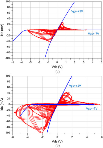
For switching transistors a different mechanism is limiting the linearity. The LO power is driving the gate of the switching transistor from pinch-off to conduction. For minimum conversion loss the nominal gate bias voltage is approximately equal to the threshold voltage. The maximum voltage swing on the gate is limited by forward conduction (for positive gate voltage) or breakdown (for negative gate voltage) of the gate–source diode. In case of a GaN transistor with a threshold voltage of −3 V, the voltage swing is limited to approximately −7 to +1 V. The DC Ids–Vds characteristic of a 2 × 75 µm switch transistor is shown in Fig. 1 in blue, for the on- and off-state (Vgs = + 1 and −7 V). This figure clearly shows the non-zero on-resistance of this small switching transistor. Also visible is that the transistor starts to conduct for large negative drain–source voltage, as soon as the gate–drain voltage is larger than the threshold voltage. This effect is limiting the maximum drain–source voltage swing and will cause the compression behavior as shown in Fig. 1. An ideal quad ring mixer has been simulated, using the 2 × 75 µm switch transistor from the UMS GH25-10 library. Figure 1(a) shows the case where the RF signal has reached the 1 dB compression point, whereas Fig. 1(b) shows the mixer in 4 dB compression. It can also be seen that the drain–source current saturation, even when using a small transistor, is not an issue at all. The advantage of a GaN switch transistor over GaAs is that the GaN transistor has a larger threshold voltage and thus a larger LO voltage swing can be allowed, giving a higher compression point.
DC IV characteristics of a 2 × 75 µm switch FET (blue) and the dynamic Ids–Vds excursion of this FET in a quad ring mixer (red) simulated up to 1 dB (a) and 4 dB (b) gain compression.

B) Conversion loss behavior
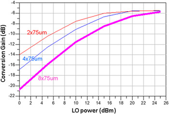
For minimum conversion loss the switching element should approach an ideal switch as good as possible: it should have a low on-resistance and low off-capacitance. This can also be expressed in terms of the reflection coefficient of the switch [Reference Yhland10]: the difference between the on-state and off-state reflection coefficient should be maximized. Selecting the best transistor size for minimum conversion loss is a trade-off between low on-resistance (large device) and low off-capacitance (small device). Analysis has shown that for the used GaN technology it is more important to have a low capacitance than a low resistance. From the available switch transistors from the GH25 library (2 × 75 µm, 4 × 75 µm, and 8 × 75 µm) the smallest device has been selected as switching element. A comparison of the simulated conversion gain using these three transistor sizes is shown in Fig. 2. As can be seen, the smallest transistor offers the lowest conversion loss. However, it must be noted that the main effect seen in this graph is that a larger transistor requires more LO power and that the minimum conversion loss is almost the same for the three transistor sizes.
Simulated conversion gain for an ideal 4 FET quad ring mixer using different size GH25 switch transistor models at V gs = − 3.0 V (RF = 10 GHz, LO = 9 GHz).

III. MIXER REQUIREMENTS AND ARCHITECTURE
The following specifications for the mixer have been defined:
-
• Image rejection >25 dB,
-
• X-band RF,
-
• 1–2 GHz IF,
-
• 0 dBm LO power,
-
• Conversion gain >0 dB,
-
• High LO–RF isolation,
-
• Low spurious output signals,
-
• Minimum power dissipation.
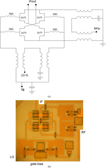
Because of the large RF bandwidth requirement, no fixed image-rejection filtering is possible, and an image-reject mixer topology is needed. Given the requirement for high LO–RF isolation, and the fact that the LO frequency falls inside the RF bandwidth so that LO filtering is not possible, a double-balanced mixing core is preferred. The easiest way to implement a double-balanced mixer core is to use a quad ring structure, which also provides easy broadband matching. The schematic and layout of the quad ring structure are shown in Fig. 3, together with the LO and RF balun. These baluns have been realized using very compact Marchand-type baluns [Reference Ang, Economides, Nam and Robertson11]. Active baluns have not been considered because these would introduce too much power dissipation. The LO balun is also used to supply the gate voltage to the mixing transistors. The ground connection for the transistors is realized via the RF balun. To optimize the performance, the 4th port of these baluns has been connected via a small capacitor to ground, instead of leaving these ports open. As discussed in the previous paragraph, a switch transistor with a small total gate width (2 × 75 µm) has been selected as switching element.
Schematic and photograph of the mixer core with the quad ring FETs, LO balun, RF balun, and differential IF output (layout area about 1 mm2).

To realize the image-rejection function two mixers are needed that operate in quadrature. Therefore a 90° hybrid is needed in the LO or RF path. To minimize the conversion loss this hybrid has been placed in the LO path. The phase and amplitude accuracy of this hybrid will determine the maximum achievable image-rejection. An expression for the achievable image rejection as function of the gain and phase imbalance in given in [Reference Gu12]:
 $$IR\, [ {\rm dB}] =10\, {\rm log}\displaystyle{{1+2\lpar 1+\delta \rpar \, cos\lpar \varepsilon \rpar +{{\lpar 1+\delta \rpar }^2}} \over {1 - 2\lpar 1+\delta \rpar \, cos\lpar \varepsilon \rpar +{{\lpar 1+\delta \rpar }^2}}}\comma \; $$
where δ is the amplitude imbalance and ε the phase imbalance.
A phase accuracy of better than 5° and amplitude accuracy better than 1 dB is needed to achieve the specified image rejection of 25 dB. Simulation has shown that the phase and amplitude balance of the LO and RF Marchand baluns play no significant role in the image-rejection limitation.
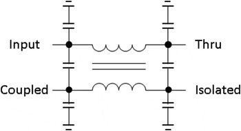
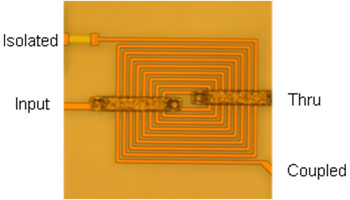
To realize the 90° hybrid, a coupled-inductor transformer [Reference Fisher13, Reference Frye, Kapur and Melville14] has been used as compromise between performance and layout area. Figure 4 shows the equivalent circuit schematic of such a hybrid. The isolated port is loaded by 50 Ω. Design equations for the component values and an implementation in CMOS technology are given in [Reference Frye, Kapur and Melville14].
Equivalent circuit of the coupled inductor hybrid.

By means of tuning the line width, spacing, and number of turns a spiral transformer implementation of this hybrid has been realized. The layout of this hybrid is shown in Fig. 5. EM simulation shows a phase accuracy of ±5° and amplitude accuracy of ±3 dB, from 6 to 12 GHz. These figures would result in a poor image rejection, <15 dB. However, due to overall circuit and layout optimization and tuning, a good image rejection with such a hybrid is possible, as shown in the measurement results. Finally, to divide the RF signal over the two mixers, a lumped-element Wilkinson splitter has been used.
Photograph of the coupled inductor 90° hybrid to realize the two LO signals.

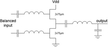
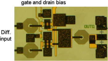
The most difficult part of the design has been the IF path. To realize a single-ended IQ-output an IF balun is needed. Because of the relatively low IF a passive balun will become quite large and lossy. An example of a possible IF balun has been shown in [Reference Mallet-Guy, Darcel, Plaze and Mancuso4], where a so-called Triformer [Reference Boulouard and Le Rouzic15] structure has been used at an IF about 2 GHz. The amplitude and phase balance performance of this structure is good, but the insertion loss is high (>6 dB, including the splitting loss) and increases rapidly for lower frequencies. To overcome this loss and to compensate for the conversion loss of the mixer core additional IF amplification would be needed, which will also require additional layout area. Instead of a passive IF balun an active IF balun has been realized to combine the balun function and IF amplification. This balun is realized with a stack of two 2 × 75 µm transistors, like a half-bridge structure. The simulated power gain is higher than 10 dB, from 0.1 to 2 GHz. An additional LC filter has been added in the output to further reduce any spurious signals. The drain bias is 10 V and the current consumption ranges from 17 to 33 mA depending on the gate bias voltage. The schematic representation of this active IF balun is shown in Fig. 6 and the layout is shown in Fig. 7.
Schematic of the active IF balun (gate bias connection not shown).

Photograph of the active IF balun.

Finally, an LO amplifier has been included. The mixer core needs approximately 15–20 dBm LO power for optimum conversion loss. The specified external LO power is 0 dBm. Therefore a two-stage amplifier has been added, consisting of a 2 × 30 µm input stage and 4 × 30 µm output stage. The transistors have been stabilized using RC feedback from drain to gate and an additional shunt resistor from the gate to the ground. The simulated power gain is higher than 15 dB and the output power is higher than 15 dBm from 6 to 10.5 GHz for an input power of 0 dBm. Drain bias is 10 V and the current consumption is about 20 mA.
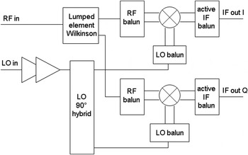
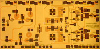
The complete architecture of the image-reject mixer is shown in Fig. 8 and Fig. 9 shows a photograph of the realized MMIC. All parts of the layout have been optimized using two-dimensional (2D) EM simulations to obtain maximum overall performance for conversion gain and image rejection. As can be seen the two mixer cores use about one-third of the total layout area. The IF baluns and the LO amplifier each use also about one-third of the area. An option in the layout has been included to bypass the LO amplifier, since simulation has shown that the bandwidth of this amplifier is limiting the bandwidth of the overall circuit. The chip dimension was not optimized, and could have been smaller, but was dictated by other designs on a multi-project wafer run.
Architecture of the double-balanced image-reject mixer.

Photograph of the GaN mixer MMIC (4.1 × 2.0 mm2).

IV. MIXER CORE TEST STRUCTURE MEASUREMENTS
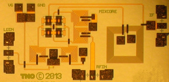
To analyze the performance of the double-balanced mixer core, a test structure has been designed consisting of only one passive mixer with a Triformer IF balun to allow single-ended IF measurements. The layout of this test structure is shown in Fig. 10.
Photograph of the GaN mixer core test structure (2.0 × 1.0 mm2).

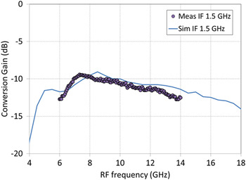
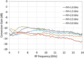
The conversion gain of this test structure has been measured versus RF at IF from 1.0 to 3.0 GHz and 15 dBm LO power. At 1.5 GHz IF frequency Fig. 11 shows that the measurement result compares very well with the simulation, indicating the accuracy of the EM simulation of the passive elements and the quad ring structure. The performance at other IF, from 1.0 to 3.0 GHz, is shown in Fig. 12 and shows the very broadband performance of the mixer core.
Measured and simulated conversion gain at 15 dBm LO power at 1.5 GHz IF.

Measured conversion gain at 15 dBm LO power for various IF.

V. MIXER SIMULATION AND MEASUREMENT RESULTS
The mixer MMIC has been measured using a 4-port PNA-X network analyzer, in order to measure both the IF-I and IF-Q output. The total conversion gain and image rejection have been calculated from I and Q data as if an ideal IF hybrid has been included. Measurements have been performed at two different bias settings: the default bias for the mixing FETs and IF balun and a maximum conversion gain bias. Power dissipation in the case of the default bias is about 170 mW for the IF balun. For the maximum gain bias the power dissipation increases to 330 mW. In both cases, the additional power dissipation for the LO amplifier is 200 mW.
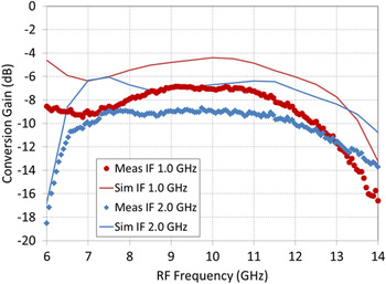
Figure 13 shows the measured and simulated conversion gain at 0 dBm LO power for 1.0 and 2.0 GHz IF at the default bias. Apart from 3 dB additional loss, the measured performance corresponds well with the simulations. Since this additional loss is not seen in the mixer core test structure it is expected that it is caused in the IF part of the circuit.
Measured and simulated conversion gain at 0 dBm LO power for 1.0–2.0 GHz IF.

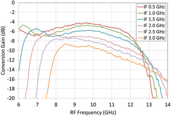
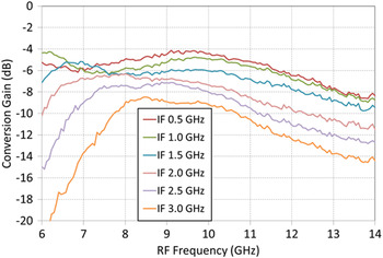
Figure 14 shows the measured conversion gain over a wider IF range, from 0.5 to 3.0 GHz IF, at the maximum gain bias setting. The best performance is obtained between 0.5 and 1.0 GHz IF, with a conversion loss of <8 dB from 6 to 12 GHz RF. At higher IF and low RF the bandwidth of the LO amplifier is limiting the performance. This has been confirmed by measurement of the conversion gain, while bypassing the LO amplifier, as shown in Fig. 15.
Measured conversion gain at 0 dBm LO power for 0.5–3.0 GHz IF at maximum gain bias setting.

Measured conversion gain, without LO amplifier, at 15 dBm LO power for 0.5–3.0 GHz IF at maximum gain bias setting.

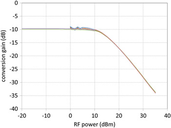
Figure 16 shows the measured RF input-power compression behavior. The power levels of I and Q IF outputs have been measured separately and are plotted together in this figure. Multiple power sweep measurements have been performed up to increasing input-power levels (10, 20, and 35 dBm) without any change in the measured small-signal performance and without any damage to the circuit. At 5 dBm LO power the input 1 dB compression point is 12 dBm. At 0 dBm LO power this level reduces to 7 dBm.
Measured conversion gain, with LO amplifier, at 5 dBm LO power for the I and Q output separately (9 GHz LO and 10 GHz RF).

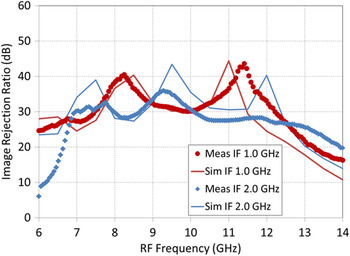
Figure 17 shows the calculated image-rejection response from the measured I and Q data, compared with the simulation, for 0 dBm LO power and 1.0 and 2.0 GHz IF. The measured image rejection in the X-band is better than 25 dB and shows good agreement with the simulation.
Measured and simulated image-rejection ratio at 0 dBm LO power for 1.0–2.0 GHz IF.

Spectrum measurements at a single IF output, before a 90° IF hybrid, have shown that the LO and RF suppression are respectively −70 and −55 dBc, at 10 dBm LO power and 18 dBm RF power. Measured LO to RF isolation is better than 20 dB in X-band, at 0 dBm LO power so including the on-chip gain of the LO amplifier. Without the on-chip LO amplifier this isolation increases to about 40 dB. Finally, the measured noise figure is <13 dB in X-band.
VI. DISCUSSION AND CONCLUSION
In this work, the first GaN integrated double-balanced image-reject mixer has been demonstrated. The design uses an integrated LO amplifier, compact baluns and hybrid and an active IF balun and has demonstrated good performance over a wide frequency range.
The measured conversion loss is <8 dB from 6 to 12 GHz RF, at 1 GHz IF, with better than 25 dB image rejection. Due to the on-chip LO amplifier, the required LO power level is only 0 dBm. Because of the extensive use of 2D EM simulations the measured performance shows good agreement with the simulations, expect for 2–3 dB less gain in the active IF balun.
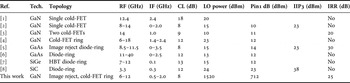
Table 1 shows a comparison of the performance of the designed mixer, without using the on-chip LO amplifier, with other published mixer MMICs in X-band and one design in S-band. Concerning linearity GaN cold-FET mixers do not show an improvement over diode-based mixers in GaAs or even SiGe technology. The best result for linearity is obtained using a SiC diode mixer, with high LO drive power.
Comparison between this work and comparable MMIC mixer designs.

The performance of the GaN mixer core is comparable to what can be achieved in GaAs technology that is optimized for mixer performance. This design experiment has however shown the feasibility of future integrated GaN-based front-end chips, such as a monolithically integrated robust LNA with down-converter, up-converter with HPA and T/R switch, or the combination of these two, using the mixer for both up- and down-conversions. In case the additional cost of the GaN chip area is a major concern, the passive parts (i.e., baluns and hybrids) could be integrated on GaAs-based or other low-loss, low-cost passive technologies.
ACKNOWLEDGEMENTS
The authors thank the support of Thales Nederland and the European Defence Agency (EDA) project MAGNUS.
 Marc van Heijningen received the M.Sc. degree in Electrical Engineering in 1998 from the Eindhoven University of Technology, The Netherlands. In 1998, he has started working as a researcher at the Interuniversity Micro Electronics Center (IMEC), Leuven, Belgium, on substrate noise coupling in mixed-signal integrated circuit. In 2001, he joined the Physics and Electronics Laboratory of the Netherlands Organization for Applied Scientific Research, TNO, in The Hague, The Netherlands, where he is working on microwave MMIC design. He has authored and coauthored over 35 peer-reviewed publications. The main focus of his work is on high-power amplifier design from L- to W-band in GaAs and GaN technology. Mr. van Heijningen was awarded the best paper award at the 1st European Microwave Integrated Circuits Conference (EuMIC) in 2006.
 Jeroen Hoogland graduated as B.S. at Rijswijk Polytechnic in 1998. His bachelor thesis was based upon his research done during graduation period at the TNO Physics and Electronics Laboratory regarding the design of 94 GHz radiometer chips. After graduation Mr. Hoogland was offered the position of Researcher at the MMIC group, where he got involved in the design and measurement of multifunctional MMICs for radar applications. Gradually Mr. Hoogland gained profound expertise in multiple on-wafer measurement techniques and equipment, next to his developing knowledge of MMIC design. Currently, Mr. Hoogland is involved in the design of an on-wafer active multi-harmonic load pull measurement system in co-operation with third parties. He has co-authored over ten peer-reviewed publications.
 Peter de Hek was born in Hardinxveld-Giessendam, in the Netherlands, on August 29, 1963. After graduating high-school (HAVO) in 1981 he started studying Electrical Engineering at Dordrecht Polytechnic, The Netherlands, where he received the B.S. degree in 1985. His bachelor thesis dealt with communication between a number of mainframe computers. After fulfilling his service in the Dutch army, he joined the TNO Physics and Electronics Laboratory in 1987. He started working on the characterization and design of antennas. Since 1990, he has been involved in the design and characterization of Monolithic Microwave Integrated Circuits. During the last years, he has been involved as project leader in a number of international projects. These projects involve the design of power amplifiers in MESFET, HFET, and HBT technology. Mr. de Hek was awarded with the price for the best oral paper presented during the GAAS/EuMW Conference in September 2001.
 Frank E. van Vliet was born in Dubbeldam, The Netherlands, in 1969. He received the M.Sc. degree (with honors) in Electrical Engineering and Ph.D. degree from Delft University of Technology, Delft, The Netherlands, in 1992 and 1997, respectively. He joined The Netherlands Organization for Applied Scientific Research (TNO), The Hague, The Netherlands, in 1997, where he is currently a Principal Scientist. In addition, he accepted a position as a Full Professor of microwave integration at Twente University in 2007, where he founded the Centre for Array Technology. He has authored and coauthored well over 150 peer-reviewed publications. His research interests include MMICs in all their aspects, advanced measurement techniques, and phased-array technology. Dr. van Vliet is a member of the ESA Component Technology Board for microwave components, a member of the EDA, CapTech IAP-01, chair of the 2012 EuMIC, founded the Doctoral School of Microwaves, and serves on the TPC of EuMIC, the IEEE International Symposium on Phased Array Systems and Technology, the IEEE CSICS, and the IEEE COMCAS.