Introduction
X band in the electromagnetic spectrum typically ranges from 8 to 12 GHz is used for short-wavelength and high-frequency applications. These applications include Radar system, Aviation, Satellite communication, defense system, research purpose, etc. [Reference Gharbi, Sekkal, Aknin and Ahyoud1, Reference Bollavathi, Dorai and Alapati2]. There are various technologies used to design an antenna in X band. Some of them are microstrip technology, substrate integrated waveguide (SIW) technology, metamaterial and metasurface technology, phased array technology, reflector technology, etc.
In recent times, it has been noticed that requirement of high-speed data in wireless and satellite communication has been increasing. High-speed data transfer can be fulfilled by using low dielectric constant substrate. Substrate Integrated technology is a promising technology in fulfilling the above requirements. SIW has gained a lot of attention as it is a planar technology in which nonplanar rectangular waveguide can be designed and can integrate active and passive elements [Reference Bozzi, Georgiadis and Wu3]. The rows of metallic vias are closely spaced in a way that it minimizes the leakage effect. The propagation characteristics of SIW structure is same as rectangular waveguide provided there is no leakage.
Broadband antenna is used effectively to analyze wide range of frequencies. They are used in many applications such as radar and EW (electronic warfare), spectrum monitoring/scanning, military, and intelligence systems. In addition to broadband antenna, high gain antennas are also used where narrow beam and targeted communication and sensing is required. Bandwidth and gain always have a trade-off and it depend upon antenna types and design. Several strategies are used to improve both gain and bandwidth. It can be improved by using array of slot antenna, incorporating superstate or lens, tapered SIW feed and leaky wave design.
Researchers have proposed many wide band and high gain antenna in X band. A circular patch is used to radiate in SIW-based cavity backed antenna and thus the high gain is achieved in paper [Reference Gharbi, Sekkal, Aknin and Ahyoud1]. In paper [Reference Bollavathi, Dorai and Alapati2], the bandwidth is enhanced by using two metallized vias in cavity backed slot antenna. The position of the vias is so opted that the antenna couples two modes that helps in increasing the bandwidth. In paper [Reference Wu, Liu and Xue4], TE20 mode is excited in wideband antennas and the fabrication cost is reduced by simplifying the structures. In paper [Reference Luo, Hu, Li, Zhang, Sun and Zheng5], two hybrid modes are used to enhance the bandwidth.
In paper [Reference Khamlichi, Touhami, Elhamadi and Badaoui6], four pair of resonator slots has been designed to enhance the bandwidth. For increasing the bandwidth of the antenna, perturbed modes in single cavity backed SIW antenna is introduced [Reference Lokeshwar, Venkatasekhar and Ravindranadh7]. Cavity backed Slot antenna with one open sidewall and two slot of different shapes are etched on the top broad wall and thus enables to increase the bandwidth [Reference Ma, Wang and Duan8]. Cavity backed antennas and slot array antennas using SIW technology is readily used in Satellite and Radar communication [Reference Khamlichi, Touhami, Elhamadi and Badaoui6, Reference Luo, Hu, Dong and Sun9]. Cavity backed slot antenna designs are proposed in [Reference Lokeshwar, Venkatasekhar and Ravindranadh7, Reference Liu, Shen and Law10]. In paper [Reference Yun, Kim and Nam11], the via hole is located above the slot that is introducing its own resonance and the second resonance can be achieved by changing the position of the hole, thereby increasing the bandwidth. Broadband Cavity backed slot antenna with bow-tie slot in is introduced in paper [Reference Mukherjee, Biswas and Srivastava12]. The bow-tie slot is used to get broadband as two hybrid modes are generated and induces a strong loading effect [Reference Mukherjee, Biswas and Srivastava12]. Cavity backed antenna for wide band application that is exciting hybrid cavity mode is proposed in paper [Reference Mukherjee and Biswas13]. Cavity backed antenna with eclipse slot at top, butterfly slot at bottom and coplanar feedline is used to combine resonant frequency in paper [Reference Feng, Yang, Yan, Zhang, Geng and Zhang14]. Cavity backed cross slot antenna with unbalanced shorting vias is proposed in paper [Reference Wu, Yin, Yu, Wang and Hong15].
In this work, high gain cavity backed slot antenna for X band with bow tie uneven eclipse slot etched on the top plane is proposed. The multi-cavity structures (Dual, Triple, and Penta cavity) is designed in which individual cavities are loaded with bow tie uneven eclipse slot of constant dimension. The dimension of the substrate in the proposed antenna is 1.8 λg × 1.67 λg × .09 λg in dual cavity, 2.55λg × 1.78 λg × .09 λg in triple cavity and 4.19λg × 1.84λg × .09 λg in penta cavity. The design shows a novel structure in which cavities are arranged in linear way so that gain can be increased, and bandwidth is also not compromised. The antenna structures are analyzed in Ansoft HFSS v.2023 (High Frequency Structure Simulator). The fabricated prototype is made on Rogers RT Duroid 5870 with relative permittivity as ɛr = 2.2 and thickness of 1.57 mm. The individual cavities are adding their own resonance thereby increasing the bandwidth. The slot dimension is constant in all the cavities so that it is configured as an array that is useful in increasing the gain. The antenna thus designed is showing significant improvement in gain as we move from dual cavity to penta cavity. Beam steering with change in the frequency of an antenna can be seen in Penta cavity structure without the use of active elements.
Design methodology for single cavity
The proposed Antenna with adjacent rectangular cavities is designed to achieve high gain and high bandwidth in “X” band (8–12 GHz). The antenna design has been analyzed for single cavity, then further extended for dual, triple and penta cavity that depicted very good results. The rows of metallic vias are arranged in such a way that rectangular cavities are formed adjacent to each other. The diameter of the via is denoted by “d” and the pitch is denoted by “s” as shown in Fig. 2(a). The slot is designed and iterated for its position in which it shows maximum impedance matching and radiates in free space to achieve maximum gain and bandwidth. The dimension (28 mm × 21 mm × 1.57 mm) of the single cavity is selected such that it excites in TE102 mode.
The selection of the diameter of the via and the pitch are done by the equations (1–2) as depicted in paper [Reference Deslandes and Wu16]:
 \begin{equation}d \leqslant \frac{{\lambda }_{{g}}}{5},\end{equation}
 \begin{equation}s \leqslant 2d{\text{,}}\end{equation}
where  ${\lambda _g}$ is the guided wavelength. Equation (1) illustrates that diameter of the via cannot be more than five times the guided wavelength and Equation (2) illustrates that pitch should be less than or equal to twice the diameter of the via. Although these equations are not always the necessary conditions, but it shows less radiation losses. The design is fed with 50 Ω microstrip to SIW feedline transition as depicted in Fig. 1. The width of the feedline is half the width of SIW cavity that is calculated by the equation given in [Reference Deslandes17]. The single cavity was first designed with a bow-tie slot that showed good impedance matching as shown in Fig. 2(a). To improve the bandwidth further, an eclipse of radius 2 mm was attached to the bow-tie slot at both ends as shown in Fig. 2(b). The slot thus designed showed improvement in the frequency band that further motivated to improve the slot. The slot was further modified by adding squares of 1 mm on eclipse distributed evenly over the surface as shown in Fig. 2(c). The uneven eclipse geometry introduces asymmetry that perturbs the surface current distribution and excites additional resonant modes in proximity. The merging of these modes results in improvement of the bandwidth and the gain or radiation characteristics. The distance ds is the distance of the slot from the feed and its position is optimized to find the maximum impedance matching, see Fig. 3(a). The comparison of all the slots is done at d s = 10 mm. Although bow-tie slot showed maximum impedance matching at distance d s (16 mm), bow-tie eclipse at distance d s (16 mm) and the modified bow-tie uneven eclipse slot is optimized at d s (10 mm) from the boundary of the cavity after multiple iteration.
Isometric view of the cavity without slot.

Isometric view of the antenna: (a) bow-tie slot, (b) bow-tie eclipse slot, and (c) bow-tie uneven eclipse slot.

(a) Variation of S11 with change in ds for bow-tie uneven eclipse slot (b) S11 Parameters of single cavity with different slots.

The S11 parameters of the various slot antenna with bow-tie slot, bow-tie eclipse slot and bow-tie uneven eclipse slot is showing good improvement as shown in Fig. 3(b).
The simulation result shows that the cavity with bow-tie slot resonate at 10.48 GHz and theoretical calculation shows the resonance at 11.5 GHz. Similarly, the simulation result for the cavity with bow-tie eclipse slot resonates at 9.89 GHz and theoretically it is resonating at 11.5 GHz and the simulation result of cavity with bow-tie uneven eclipse slot resonates at 9.91 GHz and the cavity is theoretically resonating at 11.5 GHz. All the theoretical calculation for cavity resonance frequency is done using the Equations (3–5) as given in paper [Reference Cassivi, Perregrini, Wu and Conciauro18]. The deviation in the resonant frequency is due to three reasons. Firstly, the actual size of the cavity varies as it is not closed at one end. Secondly, the introduction of different slots add its own impedance factors and lastly, the extension of cavity due to microstrip to SIW transition.
 \begin{equation}{F_{R\left( {TEm0q} \right)}} = \frac{{{c_0}}}{{2.\sqrt {{\varepsilon _r}} }}\sqrt {{{\left( {\frac{m}{{{W_{{\text{eff}}}}}}} \right)}^2} + {{\left( {\frac{q}{{{L_{{\text{eff}}}}}}} \right)}^2}} ,\end{equation}
where
 \begin{equation}{L_{eff}} = \,L - \frac{{{d^2}}}{{0.95.s}}\end{equation}
 \begin{equation}{W_{{\text{eff}}}} = W - \frac{{{d^2}}}{{0.95.s}},\end{equation}
where c o is the speed of light in free space,  ${\varepsilon _r}$ is the relative permittivity of the substrate, d and s are the diameter and pitch of the via respectively, L and W are the length and width of the reference cavity, respectively. The comparison of single cavity with various slots is shown in Table 1.
Comparison table of single cavity with various slots

The radiation pattern at Phi = 0o and Phi = 90o for different slots in single cavity is shown in Fig. 4(a, b), respectively.
(a) Radiation pattern of slots at Phi = 0° (b) Radiation pattern of slots at Phi = 900.

Design methodology for dual, triple and penta cavity
The proposed work has the cavities that are coupled adjacent to the single cavity to form dual, triple and penta cavity with the final modified slot in it. The addition of the adjacent cavities in linear manner show good improvement in the bandwidth as each cavity shows good aperture coupling and merges hybrid modes at TE102. Also, the same slot at the optimized distance from the boundary of the cavity acts as an array that is helping in increasing the gain. The distance between two slots is also optimized to get maximum impedance matching. The proposed cavities of different dimensions are shown in the Table 2.
Dimension of different cavities in the proposed antenna

The designs are as follows:
Dual cavity
The cavity-2 of the dimension 24 mm × 13.5 mm × 1.57 mm is added adjacent to the cavity-1 of the dimension 25.5 mm × 13 mm × 1.57 that allows aperture coupling and combine the hybrid mode in the cavities to increase bandwidth and gain as shown in Fig. 5(a). The surface current distribution of the dual cavity is also shown in Fig. 5(b). The dimension of the cavity-2 is optimized such that the resonance of the cavity-2 approaches closer to resonance of the cavity-1 to improve the 10-dB bandwidth. The theoretical calculation for the resonant frequency of the cavity-1 at TE102 mode is 11.5 GHz and for cavity-2 at TE102 mode is 11.7 GHz. This shows the volumetric reduction of the cavity size by 2.2 % and increase the resonance frequency by 0.2 GHz that is approximately 1.8%. The proposed dual cavity structure is analyzed for both bow-tie eclipse slot and bow-tie uneven eclipse slot. The Peak Realized Gain results shows slight improvement for bow-tie uneven eclipse slot with respect to the bow-tie eclipse slot, see Fig. 6(a, b). This encourages to choose bow-tie uneven eclipse slot for further analysis.
(a) Isometric view of dual cavity antenna; (b) surface current distribution at 11.40 GHz; (c) surface current distribution at 12.18 GHz.

Comparison of bow tie uneven eclipse slot and bow-tie eclipse slot in the proposed dual cavity structure: (a) S11 parameters and (b) peak realized gain.

The bow-tie uneven eclipse slot is etched at the top plane of the cavities to radiate in free space at the distance of d s1 = 15.4 mm that is finalized after optimization.
The distance between the two slots (denoted by s L) is also optimized at different positions and the best impedance matching is found at 12.5 mm, see Fig. 7(a). The peak realized gain and radiation efficiency over the bandwidth are 5.8 dBi and is 97% respectively. The simulated HPBW for the cavity antenna structure is 54.64o. The S11 parameter as shown in Fig. 7(b) depicts two resonance frequency one with narrower bandwidth situated in the lower frequency range and one with 770 MHz bandwidth present in the higher frequency band. To improve the bandwidth further, the resonance frequencies need to be combined that can be achieved by adding another cavity that resonate and combines hybrid modes between these two-frequency band. The S11 parameter after simulation and measurement is depicted in Fig. 7(b). The simulated and measured bandwidth is 770 and 630 MHz, respectively.
(a) S11 parameter at different SL; (b)Simulated and measured S11 parameter of dual cavity.

Triple cavity
The cavity-3 of dimension 27 mm × 13 mm × 1.57 mm is added to the dual cavity antenna structure to allow merging of hybrid modes, and this increases the 10-dB bandwidth and gain, as illustrated in Fig. 9(a). The proposed triple cavity structure is also analyzed for both bow-tie eclipse slot and bow-tie uneven eclipse slot. The bow-tie uneven eclipse slot shows improved impedance matching and peak realized gain than bow-tie eclipse slot as depicted in Fig. 8(a, b). These results encouraged to use bow-tie uneven eclipse slot for further analysis The surface current distribution of the cavity is shown in Fig. 9(b, c) and (d) at 11.24, 11.42, and 12.17 GHz, respectively.
Comparison of bow tie uneven eclipse slot and bow-tie eclipse slot in the proposed triple cavity structure: (a) S11 parameters and (b) peak realized gain.

(a) Isometric view of triple cavity antenna, (b) surface current distribution at 11.24 GHz, (c) surface current distribution at 11.42 GHz, and (d) surface current distribution at 12.17 GHz.

The S11 parameter shown in Fig. 10 of the triple cavity is self-explanatory that the resonance of the third cavity is merged to the resonance of the other two cavities as discussed in the previous section. The theoretical calculation of the cavity-3 gives the resonance frequency at TE102 mode as 10.76 GHz. The volumetric increase of the cavity-3 with respect to cavity-1 is 8% and 10% to that of cavity-2. This cavity-3 adds another resonance on the lower frequency scale with respect to the two-cavity antenna structure. The distance of the slot is optimized after multiple iteration at d s2 = 15 mm and is giving maximum aperture coupling.
Simulated and measured S11 parameter of the tri cavity.

The peak realized gain and radiation efficiency is 8.49 dBi and 98%, respectively. The HPBW of the triple cavity turns out to be 50.96o. The simulated and measured S11 parameter of the triple cavity is depicted in Fig. 10. The results depicts that the bandwidth is increased by adding adjacent cavities. The simulated and measured bandwidth thus achieved is approximately 1.2 and 1.08 GHz, respectively
Penta cavity
In this design, the cavity-4 of dimension 22.5 mm × 12.7 mm × 1.57 mm and the cavity-5 of dimension 28.5 mm × 13.5 mm × 1.57 mm are added to the triple cavity structure as shown in Fig. 12(a). The proposed penta cavity structure is also analyzed for both bow-tie eclipse slot and bow-tie uneven eclipse slot. The bow-tie uneven eclipse slot shows improved impedance matching (S11) and peak realized gain than bow-tie eclipse slot as depicted in Fig. 11(a, b). These results encouraged to use bow-tie uneven eclipse slot for further analysis.
Comparison of bow tie uneven eclipse slot and bow-tie eclipse slot in the proposed penta cavity structure: (a) S11 parameters and (b) peak realized gain.

The surface current distribution in the penta cavity is shown in Fig. 12(b, c) and (d) at 11.24, 11.42, and 12.17 GHz, respectively.
(a) Isometric view penta cavity antenna; (b) surface current distribution at 11.24 GHz; (c) Surface current distribution at 11.42 GHz; and (d) surface current distribution at 12.17 GHz.

The cavity-4 and savity-5 is added to improve the gain of the structure, the slot is arranged in such a way that array is formed that in turn helps to increase the gain over the bandwidth. The theoretical resonance of cavity-4 and cavity-5 at TE102 mode are 12.5 and 10.7 GHz, respectively. The volumetric decrease of the cavity-4 with respect to cavity-2 is 12% and the volumetric increase the cavity-5 with respect to cavity-3 is 8%. The peak realized gain and radiation efficiency of the penta cavity is 9.2 dBi and 93% respectively. The HPBW of the structure is 31.12°. This significant reduction on the HPBW helps to increase the gain by 0.5 dBi with respect to the tri-cavity antenna structure.
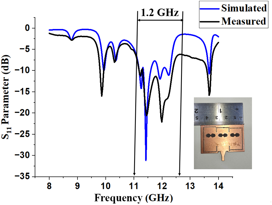
The S11 parameter of the penta cavity is shown in Fig. 13. The penta cavity structure has simulated and measured bandwidth of 940 and 1.2 GHz, respectively.
Simulated and measured S11 Parameter of the Penta Cavity.

Experimental results
Rogers RT Duroid 5870 with relative permittivity as ɛr = 2.2 and thickness of 1.57 mm is used to design the proposed antenna. The software used for simulation is Ansoft HFSS v.2023.The design aims to increase the bandwidth and gain of the proposed antenna. The improvement in the design methodology from single cavity to penta cavity antenna structures is done to increase the bandwidth and gain. The addition of constant dimension slot element inside each cavity helps to improve the peak gain of an antenna from 5.8 to 9.2 dBi in the X band. Table 3 shows the Comparison of the antenna parameters for all the four designs.
Comparison of the antenna parameters

The simulated radiation patterns at Phi = 0° is shown in Fig. 14(a). The measured gain of the antenna is very close to the simulated results. The simulated bandwidth and the peak gain of dual cavity is 770 MHz and 5.8 dBi. The measured bandwidth and the gain of dual cavity are 650 MHz and 5.8 dBi. Similarly, the simulated bandwidth and the peak gain of triple cavity is 1020 MHz and 8.49 dBi, respectively. The measured bandwidth and the peak gain of Triple cavity are 1170 MHz and 8.45 dBi, respectively. The simulated bandwidth and the peak gain of penta cavity is 970 MHz and 9.2 dBi, respectively. The measured bandwidth and the gain of penta cavity are 1260 MHz and 9.2 dBi, respectively. Figure 14(b) shows the measured radiation pattern of different cavities at different resonant frequency. Simulated and measured results exhibit strong correlation. The HPBW of the penta cavity is less than the dual and tri cavity structures.
(a) Simulated Radiation Pattern at Phi = 00 (b)Measured Radiation Pattern at Phi = 00.

Figure 15(a) depicts that the peak realized gain of the antenna with dual, triple, and penta cavity increases with the increase in the number of cavities. The simulated peak realized gain of the antenna is 5.8 dBi in dual cavity structure, 8.49 dBi in triple cavity structure and 9.2 dBi in penta cavity structure.
(a) Combined simulated and measured peak realized gain of all the proposed structures; (b) beam steering achieved in penta cavity at 11.51,11.56,11.84,12.31, and 12.49 GHz.

The measured peak realized gain of the antenna is 5.8 dBi in dual cavity structure, 8.45 dBi in triple cavity structure and 9.2 dBi in penta cavity structure. Beam steering capability of the penta cavity antenna is realized over a frequency band as shown in Fig. 15(b). The reason for beam steering is the shift of current distribution from one cavity to the other with the change in the frequency. The proposed penta structure clearly depicts beam scanning across frequencies ranging from 11.51 to 12.49 GHz and achieves scan range from −14° to +20°0. The beam scanning may not be significant, but methodology gives an approach and can be improved in future works. This type of antenna capability is useful for a variety of applications where multi-oriented communication is required, e.g., electronic warfare and defense, Radar systems working in X band.
Table 4 shows the comparison of the proposed work with other relevant reference papers. It is evident that peak gain is better in triple and penta cavity than that of all the papers listed below. The peak gain in dual cavity is better than [Reference Mukherjee, Biswas and Srivastava12, Reference Feng, Yang, Yan, Zhang, Geng and Zhang14] and [Reference Wu, Yin, Yu, Wang and Hong15]. FTBR in dual, triple, and penta cavity is better than all the comparative reference paper.
Comparison of proposed work with other relevant reference paper

The antenna was tested in the noise free environment of anechoic chamber facility along with Anritsu Site Master S820E VNA.
The test antenna was placed 1.2 m apart the reference dual-ridged horn antenna for getting the radiation patterns and realized gain. Figure 16 shows the testing of penta cavity structure both in VNA and anechoic chamber.
Testing of penta cavity structure: (a) VNA and (b) anechoic chamber.

Conclusion
The proposed antenna shows a novel linear arrangement of SIW cavity of different dimensions to enhance the gain and bandwidth simultaneously. The wideband high gain multi-cavity backed slot antenna has been proposed that shows significant increase in the band width and gain in X band. Design accuracy can be confirmed by the close match between simulated and experimental results. The bandwidth of the antenna is 770 MHz in dual cavity, 1070 MHz in Tri cavity and 940 MHz in Penta cavity. The peak realized gain varies from 5.8 dBi in dual cavity structure, 8.49 dBi in triple cavity structure and 9.2 dBi in penta cavity structure. An approach to achieve beam steering in the penta cavity structure can be used in various application in which multi-oriented communication is required. This proposed antenna can be used in satellite, wireless and radar applications.
Competing interest
The authors declare none.

Nidhi Misra is currently pursuing PhD Degree from Jaypee Institute of Information Technology (JIIT), Noida. She received a B. Tech degree in Electronics and Communication Engineering from the Dr. APJ Abdul Kalam Technical University, Lucknow (AKTU) in 2006 and received her M. Tech degree in Signal and Processing Engineering from Netaji Subhas University of Technology, New Delhi, in 2010. Her main research interests are design and optimization of high gain antennas and microwave circuits.

Abhay Kumar is currently serving as an Assistant Professor (Senior Grade) in the Department of Electronics and Communication Engineering at Jaypee Institute of Information Technology (JIIT), Noida. He has over 11 years of academic teaching experience along with 2 years of industrial research experience.
He completed his Ph.D. from JIIT Noida, specializing in substrate integrated waveguide (SIW) antennas, with applications in X, Ku, and K bands. He holds an M.Tech. in Communication Engineering from the Indian Institute of Information Technology (IIIT), Allahabad (2014), where he was awarded with the Institute Gold Medal, and a B.Tech. in Electronics and Communication Engineering from JSS Academy of Technical Education, Noida (2010).