1. Introduction
With the aging of the population and the high incidence of various accidents, the number of patients with lower limb dysfunction caused by strokes and joint injuries is increasing annually. The lower limb exoskeleton is a type of wearable device that can provide walking assistance and gait rehabilitation and shows promise in enhancing the walking ability of patients. Compared to manually assisted treadmill training, lower limb exoskeletons-assisted training exhibits the advantages of high repeatability, low labor intensiveness, and high durability and has attracted extensive attention in recent years [Reference Siviy, Baker, Quinlivan, Porciuncula, Swaminathan, Awad and Walsh1].
Lower limb exoskeletons are devices that have direct physical interaction with humans or the environment. Consequently, safe and comfortable human–robot interaction is a critical concern in the design of exoskeletons [Reference Han, Wang and Yu2]. Conventional lower limb exoskeletons often use rigid actuators with a high gear reduction ratio, such as ALEX [Reference Banala, Kim, Agrawal and Scholz3] and ReWalk [Reference Zeilig, Weingarden, Zwecker, Dudkiewicz, Bloch and Esquenazi4], which can achieve high-accuracy position control and quick response. However, the high output impedance and low backdrivability make it difficult to guarantee the safety of patients. By introducing an elastic element in series with the rigid actuator, Pratt et al. [Reference Pratt and Williamson5] proposed the concept of series elastic actuators (SEAs), which provide advantages of low output impedance, shock tolerance, high energy efficiency, and backdrivability. SEA has also found its applications in exoskeletons, such as MINDWALKER [Reference Wang, Wang, Meijneke, van Asseldonk, Hoellinger, Cheron, Ivanenko, La Scaleia, Sylos-Labini, Molinari, Tamburella, Pisotta, Thorsteinsson, Ilzkovitz, Gancet, Nevatia, Hauffe, Zanow and van der Kooij6], Symbitron [Reference Meijneke, van Oort, Sluiter, van Asseldonk, Tagliamonte, Tamburella, Pisotta, Masciullo, Arquilla, Molinari, Wu, Dzeladini, Ijspeert and van der Kooij7], and the exoskeleton developed by Zhong et al. [Reference Zhong, Guo, Yu and Zhang8]. However, the performance of SEA is limited by its fixed stiffness of the elastic element, while variable compliance allows for the adjustment of human–robot coupling characteristics within the gait cycle or mimics the human joint stiffness adjustment skills to improve performance. For instance, increasing stiffness during the stance phase guarantees torque control bandwidth and allows body weight support, while high compliance during the swing phase can reduce the resistance to human movement [Reference Zhu, Wu, Chen, Zhao and Liang9] and the impact caused by collisions.
Variable stiffness actuators (VSAs) are compliant actuators with adjustable physical stiffness, which can be classified into four types according to their working principles: antagonistic-configuration VSAs [Reference Petit, Friedl, Hoppner and Grebenstein10], spring preload-based VSAs [Reference Li, Xu and Li11], variable transmission-based VSAs [Reference Jafari, Tsagarakis, Sardellitti and Caldwell12, Reference Shao, Zhang and Ding13], and flexure-based VSAs [Reference Liu, Hong, Penzlin, Misgeld, Ngo, Bergmann and Leonhardt14, Reference Shao, Shi, Feng, Zhang and Ding15]. Inspired by human muscle actuation, antagonistic-configuration VSAs utilize two nonlinear elastic elements arranged antagonistically to adjust the joint position and stiffness simultaneously, but suffer from limitations in control complexity and energy efficiency [Reference Vanderborght, Albu-Schaeffer, Bicchi, Burdet, Caldwell, Carloni, Catalano, Eiberger, Friedl, Ganesh, Garabini, Grebenstein, Grioli, Haddadin, Hoppner, Jafari, Laffranchi, Lefeber, Petit, Stramigioli, Tsagarakis, Van Damme, Van Ham, Visser and Wolf16]. The spring preload-based VSAs can achieve decoupled control of joint stiffness and position by changing the preload of a spring and have the advantages of simple mechanism structure [Reference Li, Bai, Madsen, Chen and Zhang17]. However, the stiffness adjustment requires counterbalancing of the spring preloading force, which results in high energy consumption. By regulating the transmission ratio or effective length of leaf springs, the variable transmission-based VSAs and the flexure-based VSAs can provide a larger stiffness adjustment range and higher energy efficiency [Reference Shao, Shi, Zhang and Ding18]. However, most existing lower limb exoskeletons with VSAs can only adjust the stiffness at a slow speed, which makes it difficult to adjust stiffness during one gait cycle [Reference Grosu, Rodriguez-Guerrero, Grosu, Vanderborght and Lefeber19]. VSA-KExo [Reference Zhu, Wu, Chen, Zhao and Liang9] and L2Exo-SE [Reference Bergmann, Voss, Leonhardt and Ngo20] were designed to achieve a faster stiffness adjustment speed, while their stiffness adjustment range cannot cover the human bio-stiffness range.
Kinematic compatibility is another key feature to ensure comfortable human–robot interaction. To prevent obstructing the movement of the wearer or generating undesirable forces, the joint axes of the exoskeleton should coincide with that of the wearer. However, the axes of the existing lower limb exoskeletons cannot be completely aligned with the human joint axes, especially the three degrees of freedom (DOFs) hip joint. For example, the adduction/abduction and internal/external rotation motion are canceled in Indego [Reference Farris, Quintero and Goldfarb21], and the internal/external rotation axes of ATALANTE [Reference Gurriet, Finet, Boeris, Duburcq, Hereid, Harib, Masselin, Grizzle and Ames22] cannot intersect at the human hip joint center. To address this issue, parallel mechanisms, such as the 3-UPS mechanism [Reference Yu and Liang23], the UU-2US mechanism [Reference Wang, Guo, Qu, Song, Wang and Liu24], and the asymmetric parallel mechanism designed by Zhang et al. [Reference Zhang, Zhang, Shi and Ding25], have been used to design the hip joint exoskeletons. In addition, self-aligning mechanisms with redundant passive joints can also be used for misalignment compensation, e.g., a full-DOF hip exoskeleton was designed based on three perpendicular sliders and three rotational joints [Reference Junius, Degelaen, Lefeber, Swinnen, Vanderborght and Lefeber26]. However, these designs have limitations of complex structures and low load-bearing capacity, which makes them only suitable for single-joint exoskeletons.
Taking these issues into consideration, this study strives to design a compatible lower limb exoskeleton with variable stiffness and anthropomorphic joint mechanisms, namely CLExo, to achieve safe and comfortable human–robot interaction. A new VSA capable of wide-range and fast-speed stiffness adjustment was proposed based on a guide-bar mechanism, which allows online stiffness adjustment of the exoskeleton during one gait cycle, to change the human–robot coupling behavior and improve the performance of the exoskeleton. The stiffness range of the VSA is designed to cover the biological stiffness of the human knee joint (35–450 Nm/rad [Reference Pfeifer, Riener and Vallery27]), ensuring that the exoskeleton can adapt to the natural stiffness variations of the human body. A compact anthropomorphic hip joint mechanism based on a parallelogram linkage was designed to compensate for the misalignment between the exoskeleton and the wearer for comfortable interaction. Moreover, a multimode control strategy with low-level torque control was developed for different disease stages. Finally, the performance of the compliant actuators was evaluated by benchtop tests, and experiments with a subject were carried out to validate the performance of the exoskeleton.
The rest of this paper is organized as follows. Section 2 introduces the mechanical structure and actuator design of the exoskeleton. Section 3 describes the multimode control strategy. In Sections 4 and 5, the benchtop test of the actuators and the preliminary human subject tests of the exoskeleton are presented. Then, discussions and conclusions are provided in Sections 6 and 7.
2. Mechanical system design
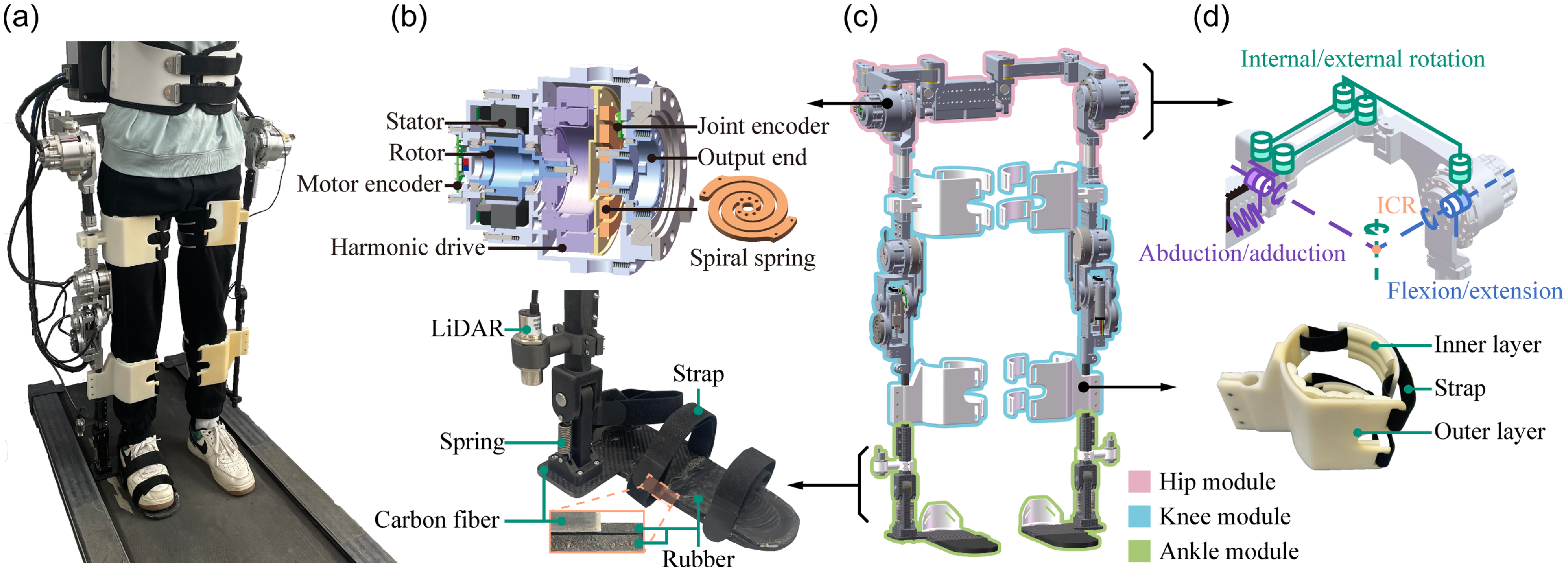
The CLExo is a powered hip–knee–ankle exoskeleton designed for walking assistance and gait rehabilitation (as shown in Figure 1), which consists of (1) a 3-DOF anthropomorphic hip joint with active hip flexion/extension (hF/E) and passive hip abduction/adduction (hA/A) and internal/external rotation (hI/E), (2) a 1-DOF knee joint for its flexion/extension (kF/E), and (3) a 1-DOF ankle joint with passive dorsiflexion/plantarflexion (aD/P), for each leg. The lengths of the thigh and shank links can be continuously adjusted to accommodate wearers of different heights. From biomechanical analysis, it is found that the bio-stiffness of the human knee joint varies along with the gait phases, while no significant stiffness adjustment occurs at the hip joint [Reference MacLean and Ferris28, Reference Cestari, Sanz-Merodio and Garcia29]. To simplify the mechanical structure of the exoskeleton, a VSA was designed to actuate the knee joint, and a SEA was developed for hip joint actuation, which guarantees safe human–robot interaction. As a preliminary validation, only the right side of the exoskeleton prototype was fabricated in this study (as shown in Figure 1(a)), which can also be used for hemiplegic patients. The total weight of the exoskeleton is approximately 16 kg, with dimensions of 990 mm (height) × 610 mm (width) × 420 mm (depth).
(a) The prototype of the exoskeleton with a human subject, (b) section view of the SEA (top) and ankle joint structure (bottom), (c) the CAD model of the exoskeleton, (d) the hip joint mechanism (top) and the binding (bottom).

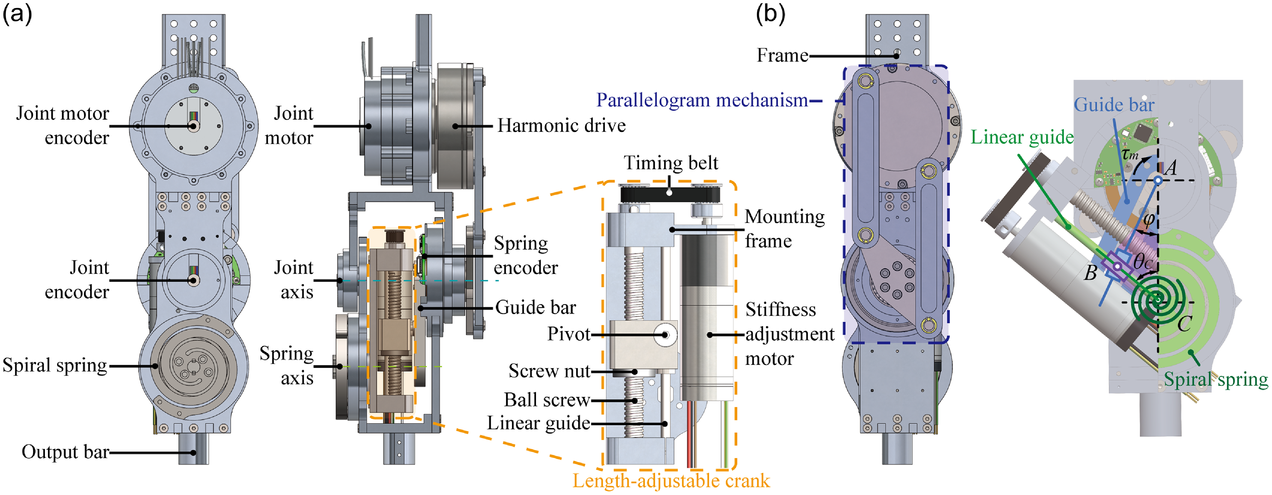
As shown in Figure 1(c), the hip module (red outline in Figure 1(c)) includes a hip joint mechanism (Figure 1(d), top) and a SEA module for active hF/E (Figure 1(b), top). The knee module (blue outline) features two bindings (Figure 1(d), bottom) and a VSA module for active kF/E (shown in Figure 2). The ankle module (green outline) is shown in Figure 1(b), bottom. Together, these modules enable coordinated movement of the lower limb.
(a) Mechanical design of the VSA, (b) schematic diagram of the variable stiffness mechanism.

2.1. Mechanical structure
The mechanical structure includes three modules: the hip module, the knee module, and the ankle module.
2.1.1. The hip module
As depicted in Figure 1(c) with a red outline, the hip module comprises three revolute joints and a parallelogram linkage to match the human hip joint’s spherical motion. The two horizontal revolute joints for hF/E and hA/A intersect at the hip joint’s instantaneous center of rotation (ICR), ensuring precise alignment with the human hip joint’s natural rotation center. For hI/E, a parallelogram linkage combined with a vertical revolute joint is employed. When the exoskeleton is worn, this mechanism generates an equivalent revolute joint that passes through the human hip joint’s rotation center, enabling the exoskeleton to self-align with the wearer’s anatomical joint. This design ensures that the exoskeleton’s motion closely matches the human hip joint’s biomechanics, minimizing misalignment and improving kinematic compatibility during walking assistance and gait rehabilitation. Similar to other lower limb exoskeletons, only the hF/E DOF is powered to provide walking assistance. The hip adduction is constrained by a spring to support the weight of the exoskeleton.
2.1.2 The knee module
As depicted in Figure 1(c) with a blue outline, the knee module is composed of a revolute joint powered by a VSA (as shown in Figure 2) and composite bindings (as shown at the bottom of Figure 1(d)) mounted on the thigh and shank links. To ensure comfortable interaction, the binding design adopts a composite structure. The outer layer of the structure is made of acrylonitrile butadiene styrene material, which enhances rigidity to guide the limbs. The inner layer of the structure is made of rubber cushion to provide soft contact and shape the limbs. Moreover, arc-shaped rigid pads are designed and connected with inelastic straps to fasten the human limbs. It is noted that the prototype of the current version mainly focuses on the stiffness adjustment performance of the joints. Therefore, it is relatively heavier and larger than traditional actuators. To solve this problem, the exoskeleton is mounted to a mobile platform, enabling the platform to bear most of its weight. Thus, it can be used for individuals with mobility impairments.
2.1.3. The ankle module
As depicted in Figure 1(c) with a green outline, the ankle module is composed of a spring-constrained revolute joint for aP/D motion and a composite foot structure. The foot structure consists of a rigid heel part and a flexible front foot part. The rear integrates a carbon fiber plate with a flexible rubber pad, whereas the front is constructed entirely from rubber. Such design allows the exoskeleton weight to be transferred to the ground without hindering the natural gait. Moreover, a LiDAR sensor is mounted on the shank link to measure the distance from the ground to the ankle, then used to detect the gait phase.
2.2. Compliant actuation unit
2.2.1. The VSA
As depicted in Figure 2(a), the proposed VSA features a two-axis configuration, where the motor axis does not coincide with the joint axis. In this case, the lateral encumbrance can be reduced to 95 mm. The proposed VSA consists of a joint motor (TBMS 6013A, Kollmorgen), a harmonic drive (LHSG-17-100, Leaderdrive), a parallelogram mechanism, and a variable stiffness mechanism. The joint motor is mounted on a frame with its output connected to the harmonic drive, to generate joint motion and torque. The output of the harmonic drive is connected to the guide bar of the variable stiffness mechanism through the parallelogram mechanism. The variable stiffness mechanism comprises a frame, a guide bar, a length-adjustable crank, an output bar, and a spiral spring. A schematic diagram of the variable stiffness mechanism is provided as shown in Figure 2(b), where AB is the guide bar, BC represents the length-adjustable crank, and AC is the output bar. The guide bar and the output bar are connected to the frame through revolute joints and can rotate around the joint axis. The length-adjustable crank is connected to the output bar through a revolute joint and is constrained by the spring. The length-adjustable crank is composed of a stiffness adjustment motor (ECX Torque 22M, Maxon) mounted on a mounting frame, a timing belt mechanism to transmit the rotation of the stiffness adjustment motor to the rotation of the ball screw, and to drive the screw nut moves along the linear guide. The pivot is fixed on the screw nut, inserted into the linear guide rail of the guide bar, and can slide along the rail. The length of the length-adjustable mechanism is defined as the distance between the pivot and the spring axis.
The sensing system of the proposed VSA includes four position sensors. Two absolute encoders (RM08 and AksIM-2, Renishaw) measure the joint angle and the deformation of the variable stiffness mechanism (angle
 $\varphi$
as shown in Figure 2(b)), and two incremental encoders (RM08, Renishaw and ENX 22 EASY, Maxon) measure the position of the joint motor and the stiffness adjustment motor.
When the joint motor is activated, the output motion of the joint motor is transmitted to the output bar through the harmonic drive, the parallelogram mechanism, the guide bar, the length-adjustable crank, and the spiral spring. When an external load is applied to the output side, an active joint torque
 $\tau _{m}$
is generated to counterbalance the external load, which deflects the spiral spring and produces a deflection angle
 $\varphi$
, as shown in Figure 2(b).
To clearly demonstrate the stiffness adjustment principle, the stiffness of the variable stiffness mechanism
 $k_{eq}$
is derived as follows. The deformation of the spiral spring
 $\theta _{C}$
(i.e., the angle between the length-adjustable crank and the output bar) is expressed as
 \begin{equation} \theta _{C}=\arcsin \left(\frac{l_{AC}\sin \varphi }{l_{BC}}\right)-\varphi, \end{equation}
where
 $l_{AC}$
represents the distance from the joint to the spring axis, and
 $l_{BC}$
is the length of the crank.
Then, the elastic energy
 $E$
of the spring is expressed as
 \begin{equation} E=\frac{1}{2}k_{C}\theta _{C}^{2}, \end{equation}
where
 $k_{C}$
is the stiffness of the spiral spring.
Consequently, the output torque
 $\tau _{m}$
and the stiffness adjustment force
 $f_{re}$
provided by the stiffness adjustment motor are derived as
 \begin{align} \tau _{m}=\frac{\partial E}{\partial \varphi }=k_{C}\theta _{C}\left(\frac{l_{AC}\cos \varphi }{\sqrt{l_{BC}^{2}-l_{AC}^{2}\sin ^{2}\varphi }}-1\right),\end{align}
 \begin{align} f_{re}=\frac{\partial E}{\partial l_{BC}}=-k_{C}\theta _{C}\left(\frac{l_{AC}\sin \varphi }{l_{BC}\sqrt{l_{BC}^{2}-l_{AC}^{2}\sin ^{2}\varphi }}\right).\end{align}
Finally, the equivalent stiffness
 $k_{eq}$
is obtained as
 \begin{equation} k_{eq}=\frac{\partial \tau _{m}}{\partial \varphi }=k_{C}\left(\frac{l_{AC}\cos \varphi }{\sqrt{l_{BC}^{2}-l_{AC}^{2}\sin ^{2}\varphi }}-1\right)^{2}+k_{C}\theta _{C}\left(\frac{l_{AC}\left(l_{AC}^{2}-l_{BC}^{2}\right)\sin \varphi }{\left(l_{BC}^{2}-l_{AC}^{2}\sin ^{2}\varphi \right)^{3/2}}\right).\end{equation}
When
 $l_{AC}$
and
 $k_{C}$
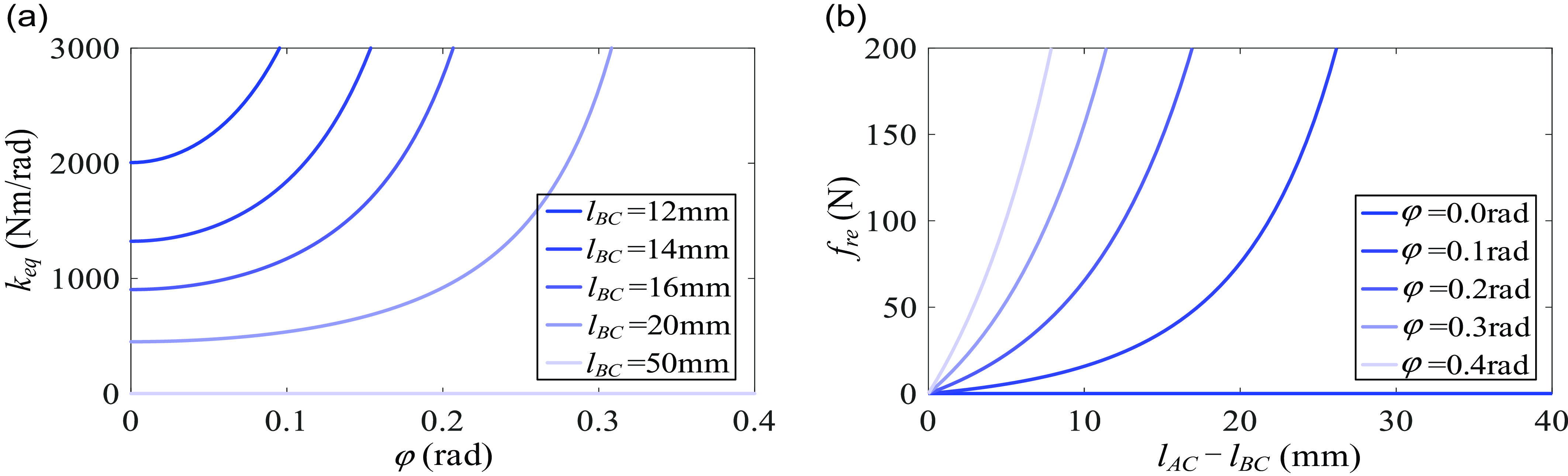
are set to 50 mm and 200 Nm/rad, the relationship between the stiffness
 $k_{eq}$
and deflection
 $\varphi$
is shown in Figure 3(a), and the relationship between the force
 $f_{re}$
and the crank length
 $l_{BC}$
is shown in Figure 3(b). It is observed that the stiffness of the actuator increases with the decreasing of
 $l_{BC}$
, and the stiffness becomes zero with
 $l_{BC}=l_{AC}$
, and approaches infinity with
 $l_{BC}=\,$
0 mm. Moreover, the stiffness adjustment force
 $f_{re}$
approaches zero during stiffness adjustment (i.e.,
 $l_{BC}$
changes) when there are no deflections, and increases with the increasing of
 $\varphi$
. Since the force applied on the pivot only has a small component parallel to its moving direction, and no preloading force needs to be counterbalanced, then the stiffness adjustment energy consumption of the proposed VSA is small when compared to the spring preload-based VSAs.
(a) The stiffness of the VSA with different
 $l_{BC}$
, (b) the stiffness adjustment force of the VSA with different
 $\varphi$
.

2.2.2. The SEA
As shown in the top of Figure 1(b), the SEA is composed of a rigid actuation and a spring. The rigid actuation includes a frameless motor (TBMS 6013A, Kollmorgen) combined with a harmonic drive (LHSG-17-100, Leaderdrive). The spring features a planar spiral design, manufactured by wire electrical discharge machining, to achieve a compact structure with constant stiffness. The spring is connected in series with the rigid actuation and linked to the output of the SEA. To measure the output angle of the motor and the SEA, two absolute encoders (AksIM-2, Renishaw) are used. Then, the deflection angle of the spring is obtained by taking the difference between the output angle of the SEA and the geared motor. Based on Hooke’s law, the output torque of the SEA can be obtained without the use of a torque sensor.
3. Control system design
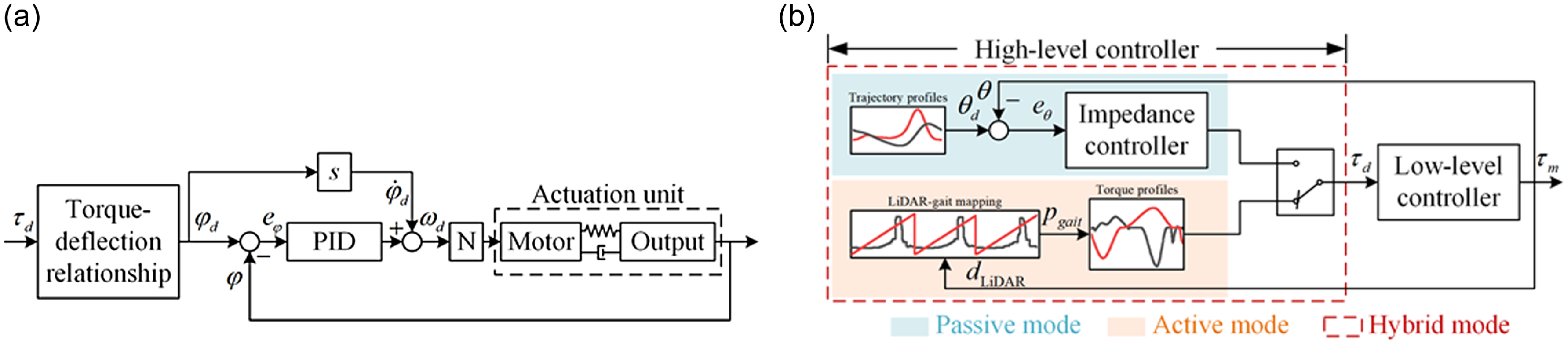
In this section, we developed a control system featuring a hierarchical architecture for CLExo, as depicted in Figure 4(b). This system comprises a low-level controller and a high-level controller. The low-level controller was utilized for performing torque control of the knee and hip joints. The high-level controller was used for detecting the gait phase and generating the assistive torque. To adapt to different diseases, three control modes, comprising passive mode, active mode, and hybrid mode, were designed specifically for the high-level controller.
Schematic representation. (a) Low-level control, (b) high-level control.

3.1. Low-level controller
The low-level controller consists of a velocity loop and a torque controller, as shown in Figure 4(a). The input of the torque controller is the desired torque
 $\tau _{d}$
generated in the high-level controller, and the output of the torque controller is the desired velocity
 $\omega _{d}$
for the geared motor. Considering the torque
 $\tau _{m}$
of the compliant actuator is a function of the deflection angle
 $\varphi$
, the control of the output torque can be converted to the control of the deflection angle. The desired deflection angle
 $\varphi _{d}$
is calculated according to the torque-deflection relationship and the desired torque
 $\tau _{d}$
, then a proportional-integrative-derivative (PID) controller is employed to track
 $\varphi _{d}$
. In addition, to decrease the burden of the PID controller, a feedforward compensator (i.e., the desired deflection velocity
 $\dot{\varphi }_{d}$
) is used.
Desired torque profiles for the hip and knee joints.

3.2. High-level controller
3.2.1. Passive mode
For patients in the early rehabilitation stage who are unable to move their lower limbs, the exoskeleton is required to provide comprehensive assistance. In this case, the passive mode was designed to track the desired joint position trajectory
 $\theta _{d}$
, which was obtained from the clinical gait data. As shown in the light blue box of Figure 4(b), an impedance controller was employed to generate the desired torque according to the position tracking error
 $e_{\theta }$
. For the sake of safety, joint position limits and velocity limits are set according to the physiological range of motion of human joints.
3.2.2. Active mode
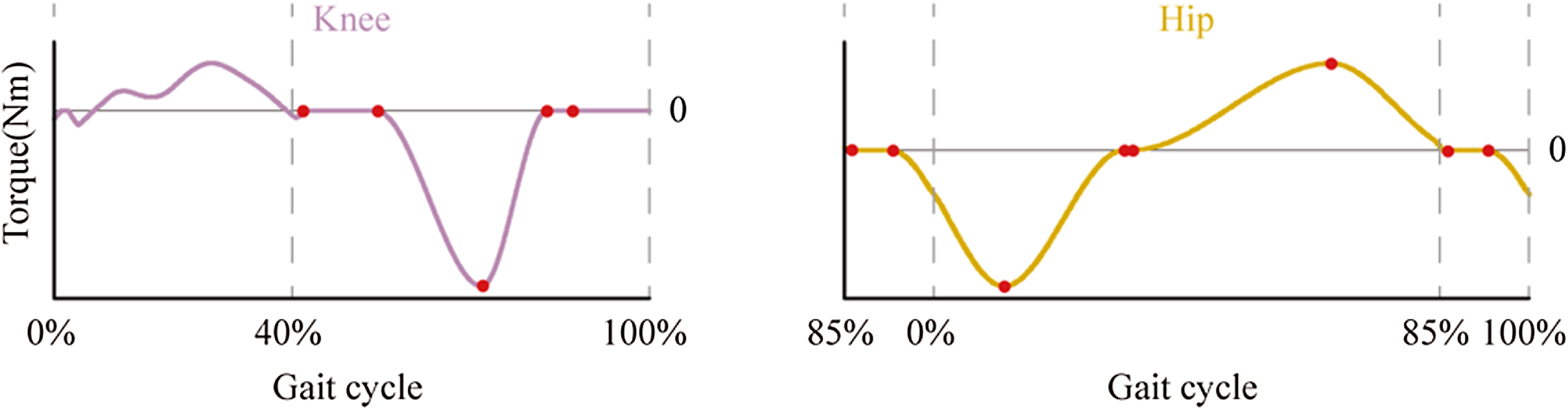
For patients in the late rehabilitation stage who possess a certain level of self-mobility, the exoskeleton is required to provide partial assistance to help the movement of human lower limbs. To this end, an active mode was proposed as shown in the light orange box of Figure 4(b), to generate the desired assistance torque according to the biomechanical analysis of human walking. To define the torque profile, we first detect the gait phase
 $p_{gait}$
of the wearer by using a LiDAR sensor, which will be detailed in Section 3.2.4. Then, a simple but effective algorithm was adopted to generate the hip and knee torque profiles as functions of the percent gait cycle [Reference Bryan, Franks, Klein, Peuchen and Collins30]. As illustrated in Figure 5, we utilized piecewise cubic Hermite interpolating polynomials (pchip) to create smooth and biomechanically relevant torque profiles. Furthermore, for knee extension during stance (
 $\sim$
0% to 40% of the gait cycle), we implemented a virtual spring to generate the desired torque, which is proportional to knee angle and becomes zero when the knee is at full extension, thereby emulating the natural resilience of the knee.
3.2.3. Hybrid mode
As a transition between the passive and active modes, a hybrid mode was designed for patients with limited mobility, as shown in the red dashed box of Figure 4(b). In this mode, the exoskeleton was used to provide weight support and ensure walking stability for the wearer during the stance phase, and provide assistance torque or follow the human lower limb movement during the swing phase. To this end, position control (i.e., passive mode) was used during the stance phase, and torque tracking control (i.e., active mode) was adopted during the swing phase. To achieve a smooth transition between the active and passive modes, we designed a torque generation function
 \begin{equation} \tau _{d}=\left(1-\omega \right)\tau _{cur}+\omega \tau _{nex}, \end{equation}
where
 $\tau _{cur}$
and
 $\tau _{nex}$
are the output torque of the current mode and the next mode, respectively, e.g., during the stance phase,
 $\tau _{cur}$
represents the output of the passive mode, while
 $\tau _{nex}$
is the output of the active mode. Conversely, during the swing phase,
 $\tau _{cur}$
and
 $\tau _{nex}$
represent the outputs of the active mode and passive mode, respectively. A weighting factor
 $\omega =0.5+0.5\tanh ((p_{gait}-p_{swit})\cdot \gamma T_{\textit{cycle}})$
is designed for modes switching, where
 $\gamma$
is a coefficient determines the duration of switching,
 $p_{swit}$
is the gait event for modes switching, and
 $T_{\textit{cycle}}$
is the gait period. Benefiting from the employment of the same low-level controller in both active and passive modes, as well as the continuity of
 $\omega$
, the assistance provided by the exoskeleton in the hybrid mode remains continuous.
3.2.4. Gait phase identification
For real-time gait phase detection, a LiDAR was utilized to identify heel strike events via threshold-based methods. The gait percentage was calculated as the time since the last heel strike divided by the average stride time. Average stride time was calculated by measuring the time between heel strikes and averaging over the last five strides. Compared to digital insoles or plantar pressure sensors, the LiDAR-based approach eliminates the need for precise sensor placement on the wearer’s feet and avoids additional wearable devices. This simplifies setup and enhances user comfort, particularly for individuals with mobility impairments.
4. Benchtop experiments
In this section, the stiffness characteristics, torque tracking performance, and torque control bandwidth of the proposed VSA and SEA are evaluated experimentally. For this purpose, a real-time control system, operating at a frequency of 1000 Hz, is implemented within the Beckhoff controller (CX5130, Beckhoff). The motors of the compliant actuators are powered by Elmo drivers (Gold Solo Twitter, Elmo Motion Control). Moreover, real-time data acquisition from the angle, force, and LiDAR sensors is accomplished via the integration of EL5042, EL6001, and EL6021 EtherCAT modules.
4.1. The VSA
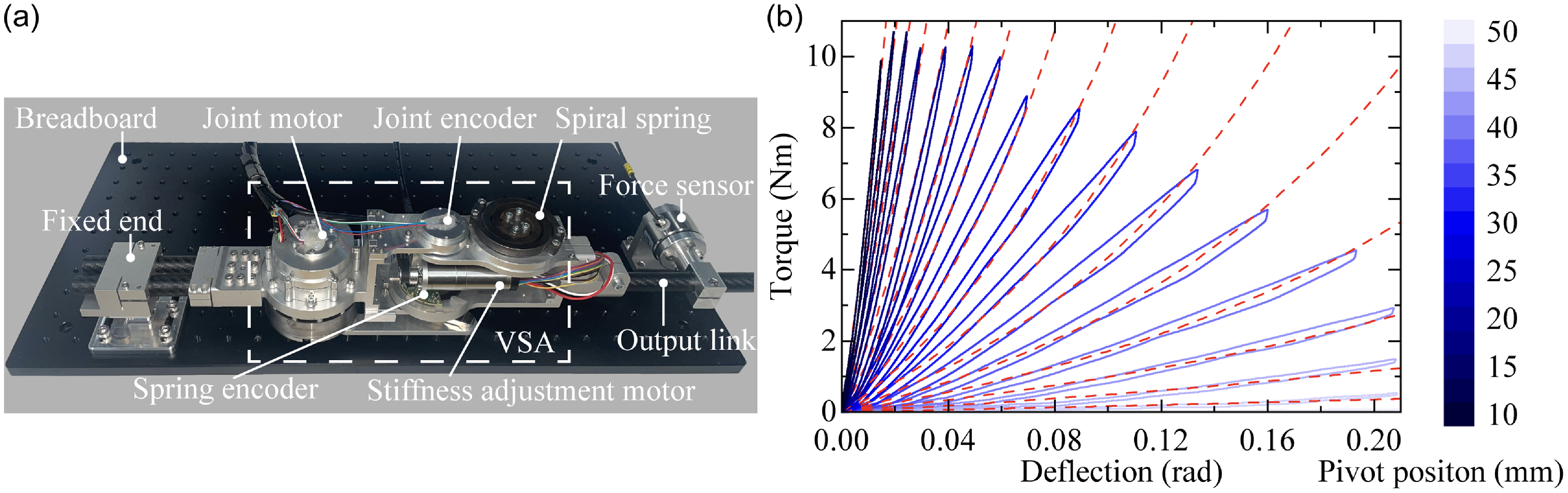
As depicted in Figure 6(a), an experimental platform is developed to perform a benchtop test of the VSA. The platform is composed of a VSA mounted on a breadboard, and its output link is connected to a force sensor (SBT673-20KG, Simbatouch), which is mounted on the breadboard. The output torque is obtained by multiplying the force applied on the force sensor and a moment arm. The detailed structural design of the VSA is depicted in Figure 2.
(a) Experimental setup for the VSA, (b) deflection–torque relationship of the VSA.

4.1.1. Stiffness calibration
The stiffness of the VSA is measured for several sets of pivot positions (i.e., the length of the length-adjustable crank
 $l_{BC}$
as in Figure 2(b)), as shown in Figure 6(b). The blue lines represent the measured data, and the red dashed lines represent the fitting results. The results indicate that the stiffness of the VSA can be adjusted in a wide range by changing the pivot position. The minimum stiffness of the actuator is approaching zero when
 $l_{BC}=\,$
50 mm, and it reaches 1301 Nm/rad when
 $l_{BC}=\,$
0 mm. The achievable maximum stiffness is smaller than the theoretical one, which is mainly caused by the compliance of the internal structures.
4.1.2. Torque trajectories tracking
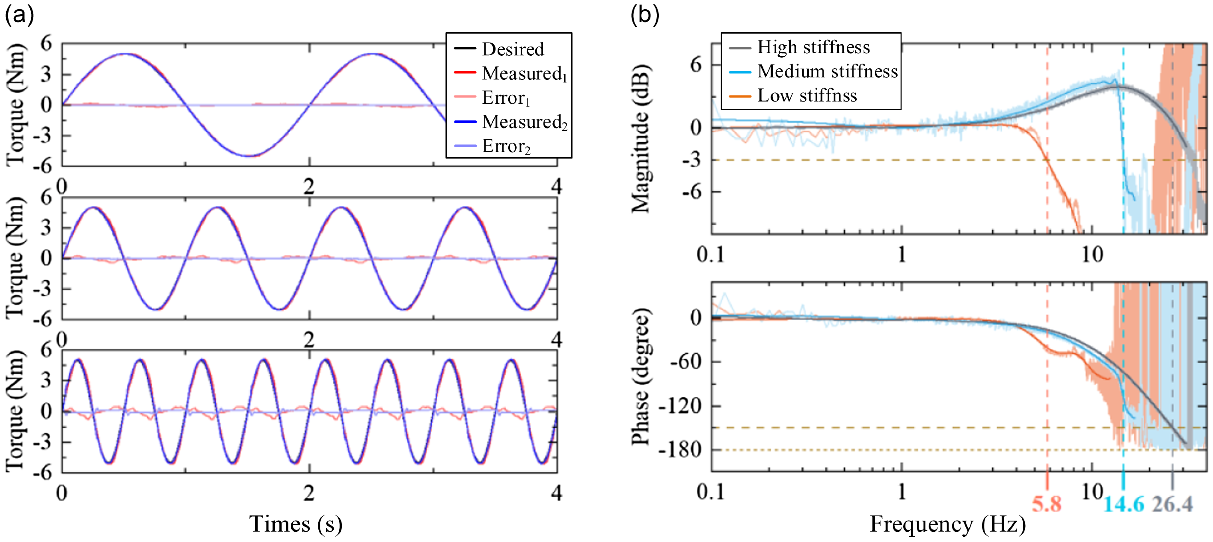
The torque tracking performance of the VSA is evaluated at different stiffness levels. The sinusoidal trajectories with an amplitude of 5 Nm and frequencies of 0.5, 1, and 2 Hz are adopted as the desired torque. As shown in Figure 7(a), the torque tracking root mean square errors (RMSEs) for VSA with low stiffness (
 $l_{BC}=\,$
40 mm, and
 $k_{eq}\approx 12$
Nm/rad) are 0.010, 0.034, and 0.135 Nm at frequencies of 0.5, 1, and 2 Hz, respectively. The torque tracking RMSEs for VSA with high stiffness (
 $l_{BC}=\,$
10 mm, and
 $k_{eq}\approx\,$
534 Nm/rad) are 0.078, 0.157, and 0.319 Nm at frequencies of 0.5 Hz, 1 Hz, and 2 Hz, respectively. The results indicate that the actuator can generate the desired torque precisely at different stiffness levels, and the accuracy can be improved by decreasing the stiffness of the actuator.
(a) Torque control results of the VSA for tracking 0.5, 1, and 2 Hz sinusoidal signals: subscript 1 represents low stiffness and subscript 2 represents high stiffness, (b) Bode diagram of chirp response result for the VSA.

4.1.3. Bandwidth test
The closed-loop torque control bandwidth is measured at three different stiffness levels, as shown in Figure 7(b). A chirp torque signal with an amplitude of 4 Nm was applied. The frequency of the signal is increased linearly from an initial 0.05 Hz at a rate of 0.5 Hz/s. The desired and measured torque were transformed into the frequency domain using a fast Fourier transform to generate a Bode plot. Taking the amplitude ratio of -3 dB and the phase margin of 30°. The results indicate that the bandwidth at low stiffness (
 $k_{eq}\approx$
12 Nm/rad) is 5.8 Hz, and increased to 14.6 Hz at medium stiffness (
 $l_{BC}=\,$
25 mm, and
 $k_{eq}\approx\,$
99 Nm/rad) and 26.4 Hz at high stiffness (
 $k_{eq}\approx\,$
534 Nm/rad).
4.1.4. Efficiency for stiffness adjustment
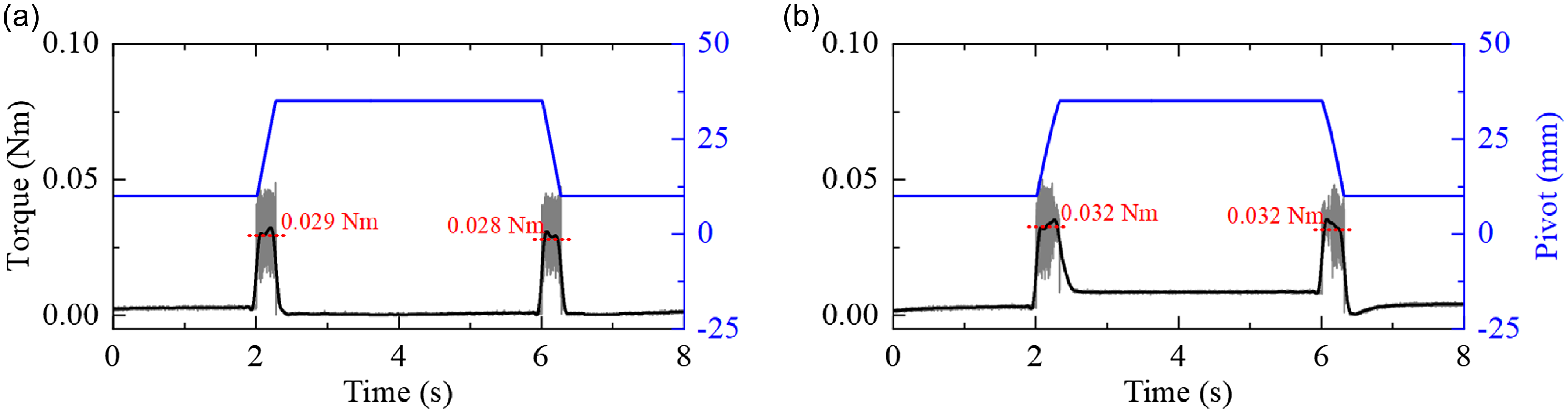
To evaluate the efficiency of stiffness adjustment, experiments were conducted under both no-load and 10 Nm external load conditions. The VSA’s stiffness was adjusted from 26 to 534 Nm/rad, corresponding to a pivot position change from 40 to 10 mm. The adjustment time was measured under both conditions. The results indicate that under no-load conditions, the adjustment is completed in approximately 0.28 s, while under a 10 Nm load, the adjustment takes approximately 0.35 s.
Additionally, the torque required by the stiffness adjustment was calculated based on the motor current readings. As shown in Figure 8, the average torque required under no-load conditions is approximately 0.029 Nm. When adjusting stiffness under a 10 Nm external load, the average torque required increases slightly to 0.032 Nm. This confirms that the proposed VSA is capable of fast and energy-efficient stiffness adjustment, even under external loads.
Results of the stiffness adjustment efficiency test. (a) Torque required by the stiffness adjustment motor for running without load, (b) torque required by the stiffness adjustment motor for driving the VSA with load.

4.2. The SEA
The SEA’s performance was evaluated through stiffness calibration, torque tracking, and bandwidth tests. The stiffness calibration results showed a linear torque–deflection relationship with a stiffness value of approximately 671 Nm/rad. The torque tracking experiments demonstrated high accuracy, with RMSE values of 0.018 Nm at 0.5 Hz and 0.136 Nm at 2 Hz. The bandwidth test indicated a torque control bandwidth of 32.7 Hz, which is suitable for real-time human motion assistance. For more details, please refer to the experimental setup and additional data provided in supplementary material.
5. Preliminary human subject tests
To verify the effectiveness of the proposed exoskeleton and the multimode controller, experiments with human subjects wearing the exoskeleton were conducted. A healthy subject (male, 24 years old, height 1.73 m, weight 58 kg) is recruited in the experiment. The participant signed an informed consent form, and the research was approved by the Beihang University Biological and Medical Ethics Committee (protocol code BM20220209).
5.1. Passive mode
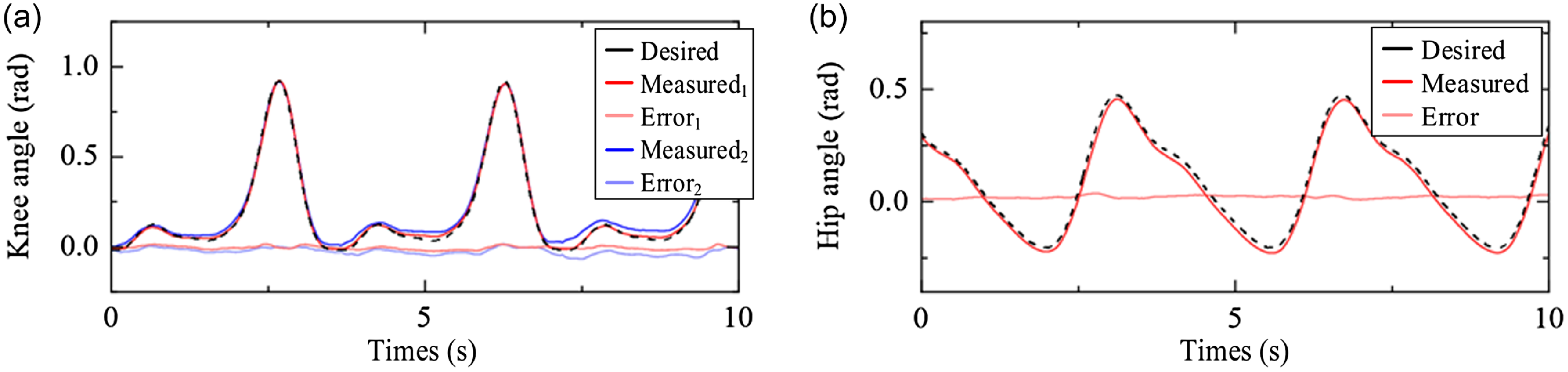
The experiments were conducted using a treadmill, and the exoskeleton was controlled in passive mode (i.e., position tracking control). During the walking trials, the participant was instructed to relax their lower limbs while wearing the robot, enabling the exoskeleton to guide the wearer along a desired trajectory. Figure 9 shows the experimental results, where the hip and knee angles were recorded by joint position sensors. To evaluate the position tracking performance of the knee joint at different stiffness levels, high stiffness (
 $l_{BC}=$
13 mm and
 $k_{eq}\approx$
400 Nm/rad) and low stiffness (
 $l_{BC}=$
32 mm and
 $k_{eq}\approx$
40 Nm/rad) were selected according to the bio-stiffness value of human knee joint during walking were considered [Reference Pfeifer, Riener and Vallery27]. The desired joint position trajectories were defined based on the clinical gait data. The results show that the exoskeleton can perform accurate position control, the position tracking RMSE is 0.021 rad for the hip joint, and 0.010 and 0.034 rad for the knee joint with high and low stiffness.
Joint trajectory tracking of the exoskeleton: subscript 1 represents high stiffness and subscript 2 represents low stiffness.

5.2. Active mode
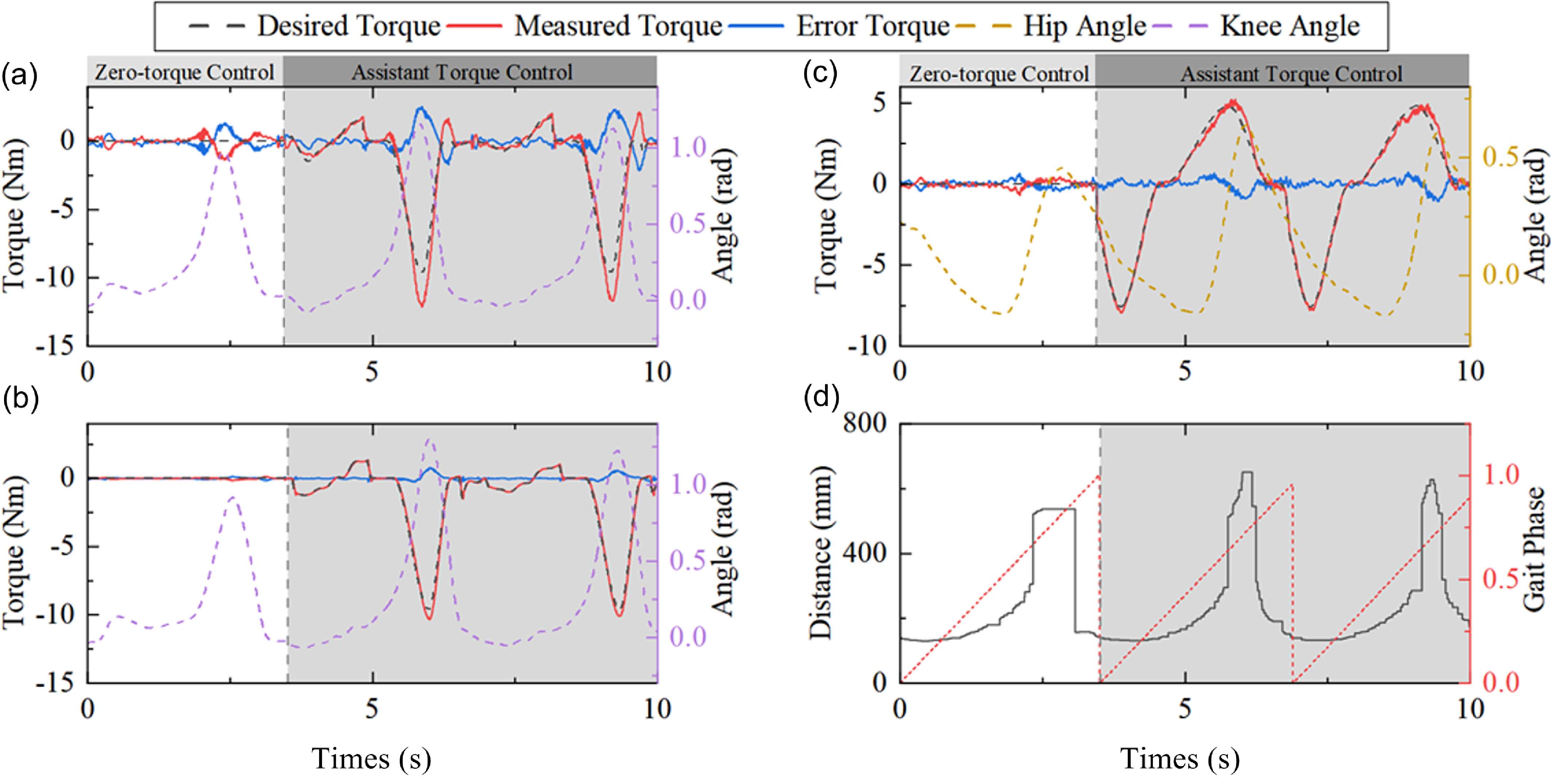
During active mode walking experiments, the exoskeleton was controlled to provide zero torque at the first 30 s, and the participant was instructed to walk on the treadmill actively. The gait phase was detected by using a LiDAR sensor (TOF laser distance sensor, ZStel). Then, the desired assistance torque was generated based on the gait phase, which was provided to the wearer to assist his walking. Figure 10 shows the experimental results, where joint angles and the interaction torques were recorded. The RMSE of the resistant torque during zero-torque control is 0.190 Nm for the hip joint and 0.044 and 0.408 Nm for the knee joint with low and high stiffness, which indicates that high transparency is achieved by the exoskeleton. For assistant control, the torque tracking RMSE is 0.329 Nm for the hip joint and 0.163 and 0.756 Nm for the knee joint with low and high stiffness.
Joint torque tracking of the exoskeleton. (a) knee with high stiffness, (b) knee with low stiffness, (c) hip, (d) the gait phase.

5.3. Hybrid mode
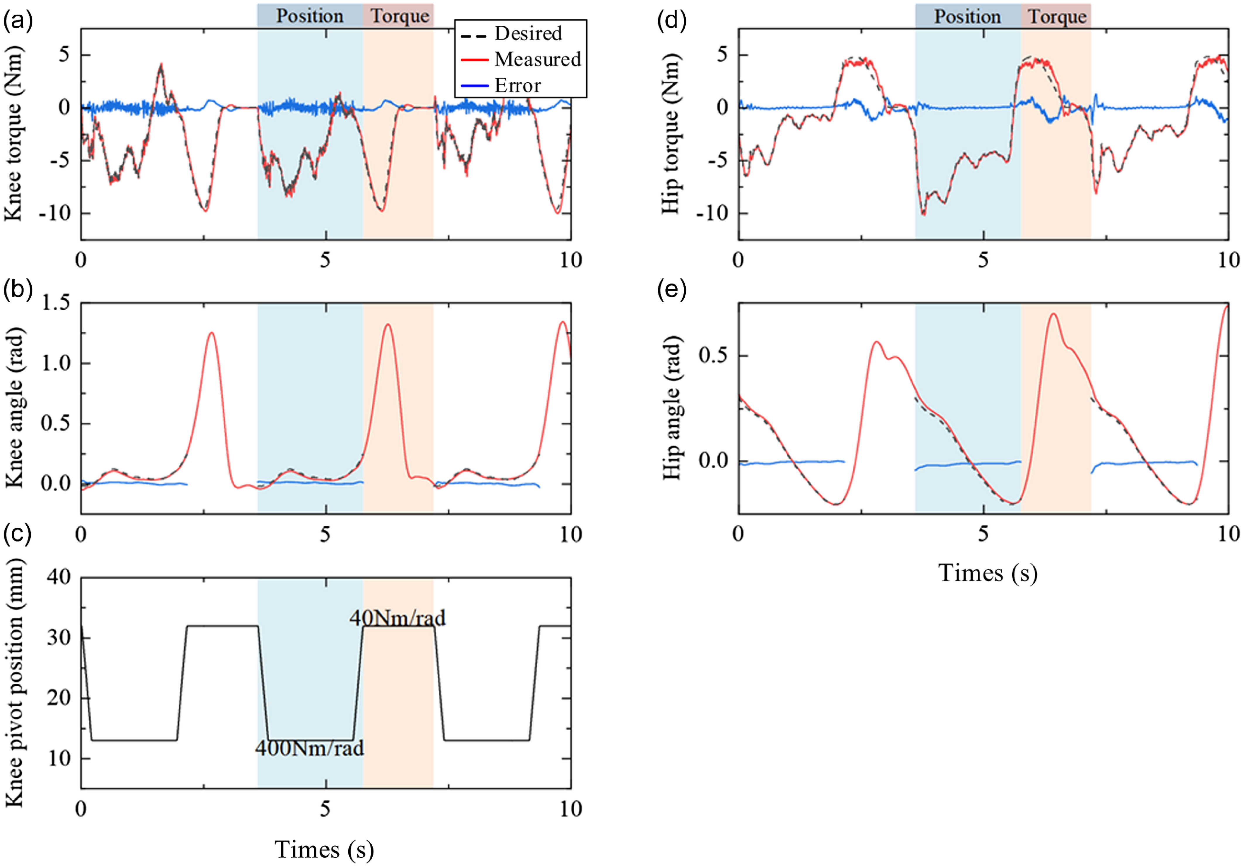
Hybrid mode walking experiments were conducted to perform position tracking control during the stance phase and torque assistant control during the swing phase. Moreover, to imitate the stiffness adjustment property of the human knee joint, the stiffness of the exoskeleton knee joint was adjusted to a high level (
 $k_{eq}\approx$
400 Nm/rad) during stance to support body weight and a low level (
 $k_{eq}\approx$
40 Nm/rad) during swing to reduce resistance to movement. The stiffness adjustment strategy also benefits the achievement of both high-accuracy joint position and torque control. As illustrated in Figure 11, the joint angle, interaction torque, and stiffness were recorded. During the stance phase, the position tracking RMSE is 0.012 rad for the hip joint and 0.009 rad for the knee joint. During the swing phase, the torque control RMSE is 0.579 Nm for the hip joint and 0.279 Nm for the knee joint. The time required for stiffness adjustment is approximately 0.25 s, which is sufficiently fast to enable real-time control within a single gait cycle.
Assistance in hybrid mode. (a) Knee torque, (b) knee angle, (c) knee VSA pivot position, (d) hip torque, (e) hip angle.

6. Discussion
6.1. Mechanical characteristics of the exoskeleton
To imitate the stiffness adjustment skills of human joints, we developed a novel VSA based on a guide-bar mechanism for knee joint actuation, which allows changing the human–robot coupling behavior to improve control performance. The stiffness of the proposed VSA can be adjusted continuously in a large range by adjusting the crank length of the mechanism. The results of the stiffness calibration experiment show that the stiffness range of the VSA is 0∼1301 Nm/rad, which covers the bio-stiffness of the human knee joint (about 35∼450 Nm/rad [Reference Pfeifer, Riener and Vallery27]). However, the other VSA-based lower limb exoskeletons can only achieve a relatively small range of stiffness adjustment, e.g., ALTACRO (5∼110 Nm/rad) [Reference Grosu, Rodriguez-Guerrero, Grosu, Vanderborght and Lefeber19] and L2Exo-SE (196∼408 Nm/rad) [Reference Bergmann, Lück, Voss, Buschermöhle, Liu, Leonhardt and Ngo31]. To allow online stiffness adjustment during one gait cycle, a fast-speed stiffness adjustment capability is required. The stiffness adjustment speed of the VSA used in L2Exo-SE, and VSA-KExo [Reference Zhu, Wu, Chen, Zhao and Liang9] are about 121 Nm/rad/s, and 697 Nm/rad/s, respectively. In our design, a speed of 2582 Nm/rad/s is achieved, which can adjust the stiffness from 10 Nm/rad to its highest value in about 0.5 s. Additionally, compared with spring preload-based VSAs such as those used in refs. [Reference Zhu, Wu, Chen, Zhao and Liang9, Reference Grosu, Rodriguez-Guerrero, Grosu, Vanderborght and Lefeber19], the proposed VSA is capable of low-energy cost stiffness adjustment, because the moving direction of the screw nut is almost perpendicular to the force generated by the spring.
In the design of the hip mechanism, we developed a serial chain by combining a parallelogram linkage and three revolute joints. Consequently, the exoskeleton hip can generate flexion/extension, abduction/adduction, and internal/external rotation motion, and the rotation axes are aligned with the human hip joint. However, the internal/external rotation is always simplified in existing designs, e.g., the joint axes of ATALANTE [Reference Gurriet, Finet, Boeris, Duburcq, Hereid, Harib, Masselin, Grizzle and Ames22] cannot all intersect at the human hip. Additionally, considering that no significant stiffness variation occurs for the human hip during level walking, an SEA is employed as the actuation unit to reduce complexity, and the stiffness is designed as 671 Nm/rad, which is between SoochowExo (400 Nm/rad) [Reference Zhang, Ning, Li and Wang32] and MINDWALKER (800 Nm/rad) [Reference Wang, Wang, Meijneke, van Asseldonk, Hoellinger, Cheron, Ivanenko, La Scaleia, Sylos-Labini, Molinari, Tamburella, Pisotta, Thorsteinsson, Ilzkovitz, Gancet, Nevatia, Hauffe, Zanow and van der Kooij6].
6.2. Torque control performance of the actuation units
The SEA can track the desired torque accurately. Specifically, the torque control RMSE is 0.018 Nm at a frequency of 0.5 Hz and 0.136 Nm at 2 Hz. Benefiting from the property of the series elasticity, high-performance torque control is realized via a simple PID controller. Moreover, the results of chirp torque tracking with an amplitude of
 $\pm$
4 Nm indicate that the torque bandwidth of the SEA is 32.7 Hz, which is similar to that of MINDWALKER (∼30 Hz) [Reference Wang, Wang, Meijneke, van Asseldonk, Hoellinger, Cheron, Ivanenko, La Scaleia, Sylos-Labini, Molinari, Tamburella, Pisotta, Thorsteinsson, Ilzkovitz, Gancet, Nevatia, Hauffe, Zanow and van der Kooij6, Reference Wang, Meijneke and Van Der Kooij33], and is higher than the typical frequency of human movement (about 4∼8 Hz) [Reference Kong, Bae and Tomizuka34]. Similarly, as shown in Figure 7(a), the torque control RMSE of the proposed VSA is 0.034 Nm (0.68% of the peak torque) at low stiffness (∼12 Nm/rad) and 0.157 Nm (3.14% of the peak torque) at high stiffness (∼534 Nm/rad), which is comparable to the control performance of VSA-KExo (RMSE is 0.496 Nm, 3.10% of the peak torque) [Reference Zhu, Wu, Chen, Xu and Shao35]. The torque bandwidth of the proposed VSA is 14.6 and 26.4 Hz for stiffness of 99 Nm/rad and 534 Nm/rad, which is larger than that in [Reference Liu, Hong, Penzlin, Misgeld, Ngo, Bergmann and Leonhardt14] (7 and 10.2 Hz for stiffness of 201 Nm/rad and 455 Nm/rad). Additionally, it is also observed that increasing stiffness results in a decrease in control accuracy but an increase in control bandwidth.
6.3. Preliminary human subject testing results
With torque-controllable compliant actuators, we proposed a multimode control strategy for different disease stages. In passive mode, the exoskeleton is controlled to lead the human leg to move along a desired trajectory. The position control accuracy is improved by increasing the stiffness of the actuator, and the position tracking RMSEs of the hip and knee joints are 0.021 and 0.010 rad, respectively. In active mode, accurate torque control is needed to provide the expected assistance torque to the patient. The experimental results indicate that the torque control accuracy can be improved by decreasing the joint stiffness. The torque control RMSE of the hip and knee joints are 0.329 and 0.163 Nm, which indicates that the exoskeleton can track the desired torque accurately. The hybrid mode consists of a position control for the stance phase to support the weight of the exoskeleton and the wearer and a torque control for the swing phase to provide assistance for human leg movement or to follow human movement with zero assistant torque. A simple weight factor is used to switch the passive and active modes continuously. By adjusting the stiffness of the actuator based on the gait phase, both high-accuracy position control and torque control can be achieved. The position tracking RMSEs for the stance phase are 0.012 and 0.009 rad for the hip and knee joint, and the torque tracking RMSEs for the swing phase are 0.579 and 0.279 Nm, respectively.
6.4. Limitations of this study
Despite the promising results, there are still limitations in this study. First, only the functionality of the exoskeleton was verified, while it is also essential to test the mechanical fatigue. Second, the stiffness of the actuator just changes between the stance and swing phases, while the human also adjusts their stiffness with the joint torque or walking condition changes. As a result, a more comprehensive stiffness adjustment strategy should be explored. Finally, only one healthy subject was involved in the experiments, more subjects and patients with strokes should be tested to verify the effectiveness of the proposed design.
7. Conclusion
In this paper, we presented the design, control, and preliminary validation of a new lower limb exoskeleton CLExo, which is characterized by compliant actuation and anatomical joint mechanisms. The design of the exoskeleton offers good force and impedance controllability, as well as kinematic compatibility. In particular, a novel guide-bar mechanism-based VSA that is capable of fast and low-energy cost stiffness adjustment over a wide range was developed, which enables stiffness adjustment of the exoskeleton during one gait cycle. The parallelogram linkage-based hip mechanism was designed to eliminate joint misalignment. The benchtop experiments show that the proposed compliant actuators allow us to conduct accurate torque control tasks with a conventional PID controller. The results of the experiments with a human subject show that the exoskeleton is effective in passive, active, and hybrid modes, to conduct accurate position tracking tasks and provide accurate assistant torque. In future work, we will conduct research on the miniaturization and lightweight design of the VSA by improving its structural design and using lightweight materials. Additionally, we will develop a comprehensive stiffness adjustment strategy that considers the time-varying characteristics of human bio-stiffness and the human–robot interaction forces, develop the left side of the exoskeleton prototype, and conduct clinical experiments with stroke patients.
Author contribution
Yufeng Zhou, Yixin Shao, and Wuxiang Zhang conceived and designed the study. Yufeng Zhou conducted data gathering and performed statistical analyses. Yufeng Zhou and Yixin Shao wrote the article. Di Shi, Yanggang Feng and Xilun Ding assisted with structure and language of the manuscript. All authors read and approved the final manuscript.
Financial support
This study was funded by the National Key Research and Development Program of China (grant number 2022YFB4701200), the China Postdoctoral Science Foundation (grant number 2024M754053), the General Program of Ningbo Natural Science Foundation (grant number 2024J045), the Ningbo Key Projects of Science and Technology Innovation 2025 Plan (grant number 2022Z070), and the National Natural Science Foundation of China (grant number 52205004).
Supplementary material
To view supplementary material for this article, please visit https://doi.org/10.1017/S0263574725000451
Competing interests
The authors declare no conflicts of interest exist.
Ethical approval
This work involved human subjects or animals in its research. Approval of all ethical and experimental procedures and protocols was granted by the Local Ethics Committee of Beihang University under Application No. BM20220209 and performed in line with the Declaration of Helsinki.