1. Introduction
The collision behaviour between liquid droplets and a superhydrophobic (SH) surface is quite common in nature and industry. Although the droplet collision seems simple and short, it is actually a rather complex physical process, with many potential mechanisms and interesting dynamic behaviours that are yet to be revealed. In particular, the droplet impacting on an SH substrate in an electric field deserves special attention and research, as it plays a fundamental role in a variety of applications, such as droplet three-dimensional manipulation (Kim et al. Reference Kim, Im, Jung and Kang2007; Chae et al. Reference Chae, Lee, Yang and Chung2015; Nauruzbayeva et al. Reference Nauruzbayeva, Sun, Gallo, Ibrahim, Santamarina and Mishra2020), water harvesting (Ilyas & Swingler Reference Ilyas and Swingler2015; Damak & Varanasi Reference Damak and Varanasi2018; Ura et al. Reference Ura, Knapczyk, Szewczyk, Sroczyk, Busolo, Marzec, Bernasik, Kar and Stachewicz2021), gas absorption (Hao et al. Reference Hao, Wang, Chen, Ma, Lan and Bai2018; Solomatin, Shlegel & Strizhak Reference Solomatin, Shlegel and Strizhak2019), inkjet printers (Mohammadi, Movahhedy & Khodaygan Reference Mohammadi, Movahhedy and Khodaygan2019; Rahman et al. Reference Rahman, Phung, Oh, Kim, Ng and Kwon2021; Zhu & Chiarot Reference Zhu and Chiarot2021) and lab-on-a-chip technology (Zhang et al. Reference Zhang, Li, Cao, Gu and Deng2019; Mozaffari et al. Reference Mozaffari, Ghasemi, Tchoukov, Czarnecki and Nazemifard2021; Sun et al. Reference Sun, Ren, Tao, Jiang and Jiang2021). When the droplet impacts on an SH surface, it will spread, retract, stretch and rebound (Yarin Reference Yarin2006; Lee et al. Reference Lee, Nam, Lastakowski, Hur, Shin, Biance, Pirat, Kim and Ybert2015). During the droplet stretching, the apex of the droplet is stretched into a curved top (Lopez-Herrera, Popinet & Herrada Reference Lopez-Herrera, Popinet and Herrada2011). While in an applied electric field, the induced charge on the droplet surface will generate an electrostatic force, which may make the top of the droplet become more pointed, so the local electric field can be strongly distorted (Lozano, Martinez-Sanchez & Lopez-Urdiales Reference Lozano, Martinez-Sanchez and Lopez-Urdiales2004; Lopez-Herrera et al. Reference Lopez-Herrera, Popinet and Herrada2011). Therefore, air breakdown or discharge could take place, seriously threatening the safety and stable operation of the equipment (Higashiyama & Saito Reference Higashiyama and Saito2013; Aouabed, Bayadi & Boudissa Reference Aouabed, Bayadi and Boudissa2017; Li et al. Reference Li, Jin, Nie, Zhang and Gao2017). Furthermore, if the electrostatic force overcomes the surface tension of the droplet, its tip could emit charged jets, which is the so-called ejection phenomenon (Luo et al. Reference Luo, Huang, Yan, Yang, Wang and He2018; Rubio et al. Reference Rubio, Sadek, Ganan-Calvo and Montanero2021). It significantly reduces operational stability and results in large losses for droplet samples. Furthermore, when the electrostatic force is weaker than or greater than the droplet gravity, the droplet may stay or detach from the substrate after the impact (Kim et al. Reference Kim, Im, Jung and Kang2007), which is of great significance for the system design of self-cleaning and droplet manipulation. Therefore, it is necessary to have a comprehensive understanding of the droplet ejection and rebound dynamics after impact under an electric field.
The ejection phenomenon is widely seen in the electrospray or electrospinning industry, so it has been studied systematically and extensively. Several different ejection behaviours have been observed experimentally (Jayasinghe & Edirisinghe Reference Jayasinghe and Edirisinghe2005; Collins et al. Reference Collins, Sambath, Harris and Basaran2013). Moreover, the effects of electric field strength, electrode placement and liquid physical properties on the ejection have been studied in detail by experiments and simulations (Jayasinghe & Edirisinghe Reference Jayasinghe and Edirisinghe2005; He & Jokerst Reference He and Jokerst2020; Jeong et al. Reference Jeong, Choi, Park, Kim, Choi, Park and Lee2020; Jones et al. Reference Jones, Moeller, Costa, Canfield and Terekhov2020). Most of the studies, however, involve sessile droplets or fluids in needle electrodes. The research on ejection following droplet impact on an SH surface is relatively limited. The ejection could become completely different when an electrostatic force is applied to a droplet impacting on an SH surface. Once the droplet impacts on an SH substrate, the sharp top of the droplet distorts the local electric field, thus affecting the subsequent ejection dynamics (Lopez-Herrera et al. Reference Lopez-Herrera, Popinet and Herrada2011). Alternatively, the inertial forces of the stretching droplet may also overcome the surface tension, causing the droplet to break up (Yarin Reference Yarin2006). Therefore, the droplet ejection dynamics is not only related to the applied electric field but also the impact behaviour.
In addition to droplet ejection, the rebound phenomenon has also attracted the attention of many researchers, because such rebound behaviour is an important phenomenon in droplet impact and is essential for self-cleaning and droplet manipulation. Many studies have found that surface structure and morphology (Bird et al. Reference Bird, Dhiman, Kwon and Varanasi2014; Chu et al. Reference Chu, Jiao, Huang, Chen, Zheng, Wang and He2020; Yuan, Matsumoto & Kurose Reference Yuan, Matsumoto and Kurose2021), surface temperature (Li et al. Reference Li, Lin, Wang, Yuan, Joo and Chen2020; Wang et al. Reference Wang, Wu, Okagaki, Alizadeh, Shamim, Hsu and Daiguji2021) and multiple droplet impact (Farhangi et al. Reference Farhangi, Graham, Choudhury and Dolatabadi2012; Mertaniemi et al. Reference Mertaniemi, Forchheimer, Ikkala and Ras2012; Wang et al. Reference Wang, Lin, Wang, Gao, Yang and Wang2020) can effectively promote or manipulate the rebound dynamics. However, it is an indisputable fact that these rebounding droplets will most likely fall back to the surface under the action of gravity, leading to droplet retention. The electrostatic force has been shown to be able to easily overcome the droplet gravity (Kim et al. Reference Kim, Im, Jung and Kang2007), and thus the use of an electric field on an SH surface can potentially address this problem.
To sum up, we are motivated to study the impact behaviour of droplet in air under electric field, especially the ejection characteristics and rebound behaviour. Four different ejection behaviours and three different rebound behaviours have been identified in this paper, including filamentous ejection not previously reported in droplet impact dynamics. The effect of impact Weber number (We) on these behaviours is also discussed. The present research results not only have important guiding significance for the electrically operated droplet device, but also may provide new understanding and guidance for other industrial applications such as electrospray (Lozano et al. Reference Lozano, Martinez-Sanchez and Lopez-Urdiales2004; Jayasinghe & Edirisinghe Reference Jayasinghe and Edirisinghe2005; Collins et al. Reference Collins, Sambath, Harris and Basaran2013), heat transfer (Miljkovic et al. Reference Miljkovic, Preston, Enright and Wang2013, Reference Miljkovic, Preston, Enright and Wang2014) and self-cleaning (Chu et al. Reference Chu, Jiao, Huang, Chen, Zheng, Wang and He2020; Yuan et al. Reference Yuan, Matsumoto and Kurose2021).
2. Methodologies
2.1. Experimental method
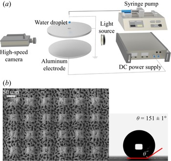
Figure 1(a) shows a schematic diagram of the experimental apparatus. As shown in figure 1(a), two aluminium plates with diameters of 10 cm and thicknesses of 5 mm are placed in parallel, and the distance between the two plates is fixed at 15 mm. To achieve a straight up electric field, the upper electrode is grounded, and the DC power (DongWenP104, China) provides voltage to the lower electrode. In this experiment, a syringe pump was used to produce a droplet with a volume of 15.5 ± 0.2 μL. A hole with a diameter of approximately 5 mm was drilled in the centre of the upper electrode. The droplet was dropped from above the upper plate and entered the electric field through the hole, further impacting on the lower electrode. Moreover, the needle was also connected to the ground to eliminate static electricity, ensuring that the water droplets did not carry any inductive charge before entering the electric field. To record and observe the details of the impact and rebound of water droplets, a high-speed camera (Olympus i-Speed TR) was mounted on the macro-lens at 5000 frames per second. Note that the droplet release height was adjusted from 15.0 mm to 50.0 mm, the corresponding Weber number We range was 12.6–42.1, with  $We = \rho _1u_0^2 d/\gamma $, where ρ 1 is the droplet density, u 0 is the droplet impact velocity, d is the droplet diameter and γ is the surface tension coefficient. Weber number We represents the effect ratio of inertial force to surface tension (Yarin Reference Yarin2006). Another important dimensionless parameter is also introduced: electric capillary number
 $Ca_e = \varepsilon _2Er/\gamma $, where ε 2 is the electrical permittivity of the environment and r is the droplet radius (Kim et al. Reference Kim, Im, Jung and Kang2007). The Cae represents the effect ratio of the electrostatic force to the surface tension.
(a) Experimental setup and schematic. (b) Microstructure of the bottom SH surface and static contact angle for a 5 μL deionized water droplet.

The lower electrode plate colliding with the droplet was an SH substrate. It was fabricated by infrared laser ablation, forming tiny columns of approximately 50 μm by 50 μm. As shown in figure 1(b), there were irregular pits and folds on the surface and bottom of the micro column, which constituted a typical micro/nano composite structure. Finally, to reduce the surface energy of the SH surface, (heptadecafluoro-1,1,2,2-tetradecyl)trimethoxysilane (C13H13F17O3Si, PTES, 1 wt%) was dissolved in methanol solution, and the aluminium electrode was immersed in the mixed solution at 70 °C for 1 h. A 5 μL water droplet was placed on the SH surface and the static contact angle was approximately 151 ± 1°, as measured by an optical angle meter (XG-CAMC33, China).
2.2. Mathematical formulation
2.2.1. Problem description
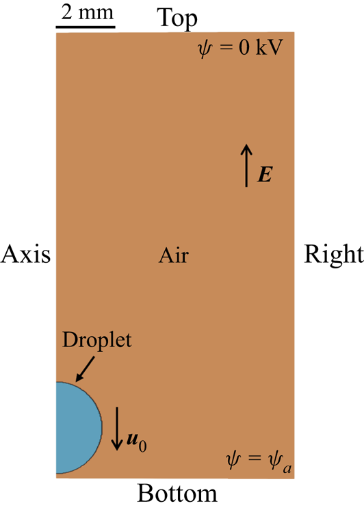
Figure 2 shows the axisymmetric computational modelling domain, which is a rectangular region with a width of 8 mm and a height of 15 mm. The droplet is liquid water, and its diameter is 3.10 mm, the same as the droplet size in the experiment. The droplet impacts the floor at a certain initial velocity, and the surrounding continuous phase is air. Boundary condition settings are shown in table 1. The top voltage is fixed at 0 kV and the bottom positive voltage is ψa, and thus the electric field is vertically upward. ‘Inlet-Outlet’ represents that the droplet can enter or exit from this boundary, which allows the ejection droplets to move out. In this study, we experimentally observed four different ejection modes from non-ejection to filamentous ejection after the droplet impinges on the SH surface. Our numerical model can reproduce the four modes well.
Computational domain and boundary conditions, with the blue colour being the droplet and the orange colour being air.

Boundary conditions of the computational domain.

2.2.2. Governing equations
In the present study, we also investigated the water droplets impacting on the SH surface under an electric field by the open-source software OpenFOAM. The air and water liquid phase equations are solved by the volume of fluid (VOF) method. The method is based on a volume fraction α, whose governing equation is (Albadawi et al. Reference Albadawi, Donoghue, Robinson, Murray and Delaure2013)
 \begin{equation}\displaystyle{{\partial \alpha } \over {\partial t}} + \boldsymbol{\nabla }\boldsymbol{\cdot }(\alpha {\boldsymbol{u}}) = \boldsymbol{\nabla }\boldsymbol{\cdot }(\alpha (1-\alpha ){\boldsymbol{u}}_{c}),\end{equation}
where α = 1 for the cells filled with liquid water, 0 < α < 1 for the cells filled with both gas and liquid and α = 0 for the cells filled with gas. Here, u is the velocity vector (all the vectors in this study are in bold). The interface sharpening is achieved by introducing the compression velocity uc, which is calculated in the normal direction of the interface, and the expression for uc can be written as (Albadawi et al. Reference Albadawi, Donoghue, Robinson, Murray and Delaure2013)
 \begin{equation}{\boldsymbol{u}}_{c} = {\boldsymbol{n}}_{f}\min \left[ {C_\gamma \displaystyle{{|\phi_m|} \over {|S_f|}},\;\max \left( {\displaystyle{{|\phi_m|} \over {|S_f|}}} \right)} \right],\end{equation}
where nf is the normal vector of the cell surface, Sf is the cell surface area, Cγ is a compression coefficient and Φm is the mass flux. Since this simulated physics problem is mainly dominated by capillary force in this study, the Cγ value is set to 1 (Albadawi et al. Reference Albadawi, Donoghue, Robinson, Murray and Delaure2013). The physical properties of the two immiscible fluids can be given by (Tomar et al. Reference Tomar, Gerlach, Biswas, Alleborn, Sharma, Durst, Welch and Delgado2007; Albadawi et al. Reference Albadawi, Donoghue, Robinson, Murray and Delaure2013)
 \begin{gather}\rho = \rho _1\alpha + \rho _2(1-\alpha ),\end{gather}
 \begin{gather}\mu = \mu _1\alpha + \mu _2(1-\alpha ),\end{gather}
 \begin{gather}1/\sigma = \alpha /\sigma _1 + (1-\alpha )/\sigma _2,\end{gather}
 \begin{gather}1/\varepsilon = \alpha /\varepsilon _1 + (1-\alpha )/\varepsilon _2,\end{gather}
where subscripts 1 and 2 represent water and air, respectively, ρ is the fluid density, μ is the fluid viscosity, σ is the conductivity and ε is the permittivity.
The phenomenon of electro-hydrodynamic (EHD) is complicated by the migration of electric charge and the fluid movement. The electrostatic force may change the fluid motion or deform the interface, which in turn can affect the distribution of charge and thus change the electrostatic force (Lopez-Herrera et al. Reference Lopez-Herrera, Popinet and Herrada2011). Therefore, to determine the electric charge distribution inside the flowing liquid, we need a charge conservation equation, which is expressed as (Lopez-Herrera et al. Reference Lopez-Herrera, Popinet and Herrada2011)
 \begin{equation}\displaystyle{{\partial \rho _e} \over {\partial t}} + \boldsymbol{\nabla }\boldsymbol{\cdot }(\rho _e{\boldsymbol{u}})-\boldsymbol{\nabla }\boldsymbol{\cdot }(\sigma \boldsymbol{\nabla }\psi ) = 0,\end{equation}
where ρe is the volumetric electric charge density, ψ is the electric potential and σ is the conductivity. Note that ion diffusion is ignored in this study. This is because the diffusion phenomenon is mainly caused by temperature and concentration differences. In this study, the droplet is deionized water with a very low ion content and the electrical conductivity of the water is approximately 10−5 S m−1. In addition, the air is considered to be free of any ions, and the whole calculation domain is set at room temperature without any temperature gradient. Therefore, (2.7) only involves the ohmic charge conduction and charge convection. The electric charge density ρe in the domain can be obtained by solving the Poisson equation as (Tomar et al. Reference Tomar, Gerlach, Biswas, Alleborn, Sharma, Durst, Welch and Delgado2007)
 \begin{gather}\boldsymbol{\nabla }\boldsymbol{\cdot }(\varepsilon \boldsymbol{\nabla }\psi ) = {-}\rho _e,\end{gather}
 \begin{gather}{\boldsymbol{E}} = {-}\boldsymbol{\nabla }\psi ,\end{gather}
where ε is the permittivity and E is the electric field. Moreover, hydrodynamics and electrical phenomena can be coupled by adding the electrostatic force to the source term of the momentum conservation equation, which is given by (Mohammadi et al. Reference Mohammadi, Movahhedy and Khodaygan2019)
 \begin{gather}\rho \left( {\displaystyle{{\partial {\boldsymbol{u}}} \over {\partial t}} + {\boldsymbol{u}}\boldsymbol{\cdot }\boldsymbol{\nabla }{\boldsymbol{u}}} \right) = {-}\boldsymbol{\nabla }p + \boldsymbol{\nabla }\boldsymbol{\cdot }[\mu (\boldsymbol{\nabla }{\boldsymbol{u}} + \boldsymbol{\nabla }{\boldsymbol{u}}^T)] + {\boldsymbol{F}}_{\gamma } + {\boldsymbol{F}}_{\boldsymbol{e}} + \rho {\boldsymbol{g}},\end{gather}
 \begin{gather}\boldsymbol{\nabla }\boldsymbol{\cdot }{\boldsymbol{u}} = 0,\end{gather}
where p is pressure, μ is viscosity, g is gravity acceleration, Fγ is the interfacial tension and Fe is the electrostatic force. Here, Fγ can be obtained by (Dastourani, Jahannama & Eslami-Majd Reference Dastourani, Jahannama and Eslami-Majd2018)
 \begin{equation}{\boldsymbol{F}}_{\gamma } = \gamma k(\boldsymbol{\nabla }\alpha ),\end{equation}
where γ is the surface tension coefficient and k is the interface curvature. The divergence of the Maxwell stress tensor T is the electrostatic force Fe (Mohammadi et al. Reference Mohammadi, Movahhedy and Khodaygan2019):
 \begin{equation}{\boldsymbol{F}}_{e} = \boldsymbol{\nabla }\boldsymbol{\cdot }{\boldsymbol{T}} = \rho _e{\boldsymbol{E}}-{\textstyle{1 \over 2}}E^2\boldsymbol{\nabla }\varepsilon .\end{equation}
In addition, when the droplet spreads and retracts, the contact angle does not remain at a certain constant value but changes dynamically. Thus, to more accurately simulate the droplet impacting behaviour, the dynamic contact angle model proposed by Kistler was adopted (Jiang, Zhou & Wang Reference Jiang, Zhou and Wang2018):
 \begin{equation}\theta _d = f_H(Ca + f_H^{{-}1} (\theta _e)),\end{equation}
where Ca is the capillary number,  $Ca = \mu {\boldsymbol{V}}_{{\boldsymbol{cl}}}/\gamma $, Vcl is the contact line velocity, θe is the equilibrium contact angle and fH is the function of the Hoffman's empirical function, which is described by Jiang et al. (Reference Jiang, Zhou and Wang2018)
 \begin{equation}f_H = \arccos \left\{ {1-2\tanh \left[ {5.16{\left( {\displaystyle{x \over {1 + 1.31x^{0.99}}}} \right)}^{0.706}} \right]} \right\}.\end{equation}
In this experiment, the bottom electrode plate is the SH surface, and the spreading and retraction for the three-phase line are influenced by the dynamic contact angle. To couple this effect in the numerical model, θe in (2.14) is replaced by the advancing contact angle θa when the three-phase line is spread and by the receding contact angle θr when the three-phase line is retracted. Furthermore, the leaky-dielectric model is adopted in this study. The conductivity σ 1 of deionized water is 10−5 S m−1, the electrical permittivity ε 1 of deionized water is  ${\rm 7 \times 1} 0^{- 10}\ {\rm F}\ {\rm m}^{-1}$, the density ρ 1 of deionized water is 998 kg m−3, the viscosity μ 1 of deionized water is 10−3 Pa⋅s and the surface tension γ is 0.072. The electric relaxation time
 $\tau _e = \varepsilon _1/\sigma _1 = 70\;{\rm \mu }{\rm s}$, which is much less than the impact characteristic time (∼10 ms). In this study, droplets can be considered as neither a perfect conductor nor a perfect dielectric, thus the leaky-dielectric model is necessary.
2.2.3. Numerical methodology
The two-phase EHD based on the VOF approach is implemented by OpenFOAM. Standard second-order accurate finite-volume procedures available in OpenFOAM are used to discretize the governing equations. The Laplace term is discretized by the second-order accurate central difference scheme and the gradient term is discretized by the third-order accurate cubic scheme. In general, the convection terms are discretized by the third-order accurate QUICK scheme, while the convection term in the charge conservation equation is discretized by the second-order accurate total variation diminishing (TVD) Van Leer scheme. The implicit Euler backward method is employed to discretize all the time derivatives. The sequence iteration method based on the PIMPLE algorithm is used to solve the discretization equation. Based on the OpenFOAM standard solver, we write the EHD equation and the dynamic contact angle equation on it, which has been published in the supplementary material available at https://doi.org/10.1017/jfm.2022.234.
2.2.4. Grid independence analysis
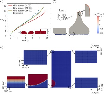
Figure 3(a) shows the grid independence analysis. The grid numbers of 54 000 to 216 000 have been calculated to evaluate the computational accuracy. The droplet stretched height of grid numbers 150 000 and 216 000 is almost the same as that of the experiment; therefore, the grid number was set as 150 000 in this study. The grid partition with grid number 150 000 is shown in figure 3(c), the entire computing domain has 200 grids horizontally and 750 vertically. In the horizontal direction, the grid size increases from 18.5 μm to 74 μm in a certain proportion, and the grid in the droplet region is relatively dense. In the vertical direction, the grid is evenly distributed with a size of 20 μm. Previous studies have shown that the charged thin layer is mainly concentrated at the fluid interface, and the size difference between the charged thin layer and droplet is often a major difficulty in VOF simulation, requiring a sufficiently fine mesh to reproduce the charged thin layer (Saville Reference Saville1997; Ferrera et al. Reference Ferrera, Lopez-Herrera, Herrada, Montanero and Acero2013; Ganan-Calvo et al. Reference Ganan-Calvo, Lopez-Herrera, Rebollo-Munoz and Montanero2016). Figure 3(b) shows the distribution of charge inside the droplet with 150 000 grids. Thin layers of electric charge are concentrated at the top and bottom of the droplet, which proves that the grid partition is accurate. The electrode in contact with the droplet has a positive voltage, so the electrode carries some positive charge, causing the solid–liquid interface to induce some negative charge.
(a) Grid independence analysis for grid number, where h 0 is the initial droplet stretched height. (b) Charge distribution inside the droplet. (c) Meshing cell size, where the blue represents air and red represents droplet.

3. Results and discussion
3.1. Droplet ejection dynamics and numerical validation
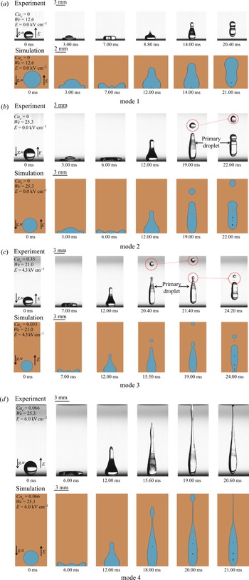
Upon the collision between the droplet and the SH surface, the inertial force can facilitate the horizontal spread of the three-phase line, and even promote the droplet stretching when the liquid–solid contact line retracts. At this point, if the surface tension can overcome the stretch kinetic energy at the droplet apex, the droplet will not eject, otherwise, it will eject (Yarin Reference Yarin2006). Figures 4(a) and 4(b) show the impact process of the droplet at the Weber number of 12.6 and 25.3, respectively. It can be found that when the impacting Weber number is low (figure 4a), the droplet could remain as a whole and does not eject or break up throughout the impact process, which is named mode 1, the same dynamic behaviour can occur when the electric field is very weak. However, when the impacting Weber number is high (figure 4b), the stretching kinetic energy is large, and a satellite droplet could split out at the apex, which is named mode 2. If the impact Weber number is large enough, even if the electric field is very weak, mode 2 will still appear. In mode 3, when the applied electric field is moderate, as shown in figure 4(c), the stretching kinetic energy could also cause the droplet to eject some satellite droplets first, and the primary droplet then continues to eject some satellite droplets from the apex. Note that the droplet can completely detach from the substrate (21.4 ms) in the experiment, but in the simulation, the bottom of the droplet sticks to the substrate, even though the substrate is superhydrophobic. The electrode in contact with the droplet has a positive voltage, so the electrode carries some positive charge, causing the solid–liquid interface to induce some negative charge. Electrostatic suction is generated between the bottom of the droplet and the electrode due to the mutual attraction of opposite charges. In the simulation, because the electrode plate is assumed to be a smooth superhydrophobic surface, the liquid–solid interface is a face-to-face contact. However, in reality, the superhydrophobic surface has a micro/nano structure, so the liquid–solid interface is a point-to-face contact. In the experiment, the negative charge induced at the bottom of the droplet may be less, so the electrostatic suction is not sufficient to stick the droplet to the electrode plate. Although the bottom of the droplet may not be very similar to that in experiment, the ejection at the apex is similar enough to reveal the ejection mechanism. In mode 4, because the electric field is so strong, the apex of the droplet quickly stretches and forms an exceptionally fine filament, as shown in figure 4(d), which eventually breaks into many smaller droplets. It should be pointed out that mode 4 is similar to the ejection phenomenon of sessile or pendant droplets studied previously (Saville Reference Saville1997; Ferrera et al. Reference Ferrera, Lopez-Herrera, Herrada, Montanero and Acero2013). For the deionized water in this experiment, the electric relaxation time is approximately 70 μs, which is much smaller than the motion time scale of the contact line (10 ms). So, migration of the three-phase line has little effect on the filamentous ejection.
Sequential snapshots showing four dynamic modes of droplets on experiments and simulations: (a) We = 12.6, Cae = 0.000 (mode 1); (b) We = 25.3, Cae = 0.000 (mode 2); (c) We = 21.0, Cae = 0.035 (mode 3); (d) We = 25.3, Cae = 0.066 (mode 4).

To sum up, with the change of impact We and electric field, the ejection behaviours for droplets are also significantly different, which is mainly the result of the interaction between the inertia force, surface tension and electrostatic force. To better explore the ejection mechanism in different modes, a numerical model that can well reproduce the four ejection behaviours is necessary. Figure 4 shows a comparison between experimental and simulated droplet ejection dynamics. It can be found that our numerical model can reproduce the droplet impact phenomenon under different electric fields and Weber number, and the four different droplet ejection modes can also be simulated well. Therefore, the numerical model is helpful for a systematic and in-depth understanding of the droplet impacting on the SH surface in an electric field.
3.2. Mechanisms of the four modes
Droplet ejection always occurs when it is stretched and the three-phase line is retracted, most likely because the top of the droplet becomes sharp during stretching, distorting the nearby electric field and generating a concentrated electrostatic force. At the same time, the sharp top of the droplet may also produce a large downward capillary force, promoting the droplet to shrink (Yarin Reference Yarin2006). In this section, the distribution of the electric charge and electric field, as well as the static pressure, dynamic pressure, capillary pressure and electrostatic force will be discussed.
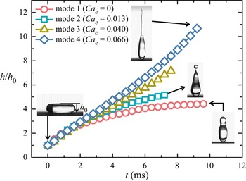
Figure 5 shows the stretch height ratio h/h 0 for four ejection modes, where h is the droplet stretch height, measured from the droplet bottom to the top, and h 0 is the droplet initial stretch height, as shown in figure 5. The droplet could be stretched by its own kinetic energy and electrostatic force. In modes 1 and 2, the droplet apex is slowly stretched and levelled off. However, in modes 3 and 4, the droplets are stretched quickly until they eject. A rough explanation might be that an increase in the electric field would encourage the droplet to stretch. However, its morphology will also change during stretching, so the distribution of the electric charge and electric field will be significantly affected.
Droplet stretching height ratio in four ejection modes before ejection (We = 12.6), where the data are measured from experiments.

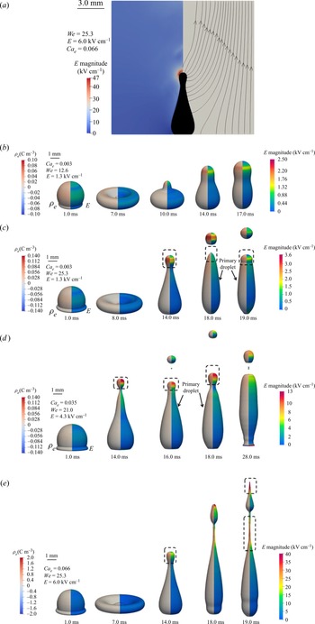
Figure 6(a) shows the electric field distribution in the air. The stretched droplet can strongly distort the surrounding electric field due to its sharp apex. Such an electric field distortion further promotes the generation of induced charge on the apex. Figure 6(b–e) depicts the charge density and electric field distribution on the droplet surface in the course of the impact. During the droplet spreading, the electric charge and electric field are evenly distributed on the droplet surface. When the droplet stretches upward, in mode 3 and mode 4, the apex of the droplet becomes sharp, and both the charge and electric field are significantly concentrated at the apex, indicating that the electrostatic force is also enhanced at the droplet top and increases sharply. However, in mode 1 and mode 2, the accumulation of charge and electric field is not obvious, suggesting that the electrostatic force is not the dominant factor in these two modes. By comparing figures 6(c) and 6(d), after the ejection of the first satellite droplet, if the primary droplet apex has obvious charge accumulation and electric field distortion, it will be subjected to a strong electrostatic force, and the next ejection can occur (figure 6d). However, if charge accumulation or electric field distortion is not significant, subsequent ejections will not be formed (figure 6c). In figure 6(e), as well as the droplet apex, a large amount of electric charge and a strong electric field also accumulate on the surface of the liquid filament, which promotes further elongation and fracture of the filament.
(a) Electric field distribution in air. The left region represents the distribution of the electric field, the right region represents the electric field lines and the black area in the middle shows the liquid droplets. (b), (c) and (d) electric charge (left) and electric field distribution (right) on the droplet surface. The data are obtained from simulations. (a) Distribution of electric field in air, (b) We = 12.6, E = 1.3 kV cm−1 (mode 1), (c) We = 25.3, E = 1.3 kV cm−1 (mode 2), (d) We = 21.0, E = 4.3 kV cm−1 (mode 3) and (e) We = 25.3, E = 6.0 kV cm−1 (mode 4).

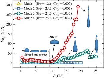
According to the above analysis, the concentrated distribution of the electric field and charge may result in a significant increase in the electrostatic force, thus facilitating stretching or ejection. We obtained the vertical upward electrostatic force Fez 1 during droplet impact by means of simulation. Figure 7 shows the variation of Fez 1 in the four modes. When the droplet is in the spreading and retracting stage, Fez 1 is weak and has no obvious fluctuation due to the absence of charge accumulation and electric field distortion. When the droplet is stretched, however, Fez 1 changes differently. Here, Fez 1 can increase to 0.56 μN in mode 1 and 2.27 μN in mode 2. The electrostatic force in modes 1 and 2 is very weak, suggesting that the ejection in mode 2 may be caused by the inertial forces of droplet stretching. In mode 3, as the droplet begins to stretch, Fez 1 increases slightly, but suddenly decreases after the first ejection, probably because the apex of the primary droplet becomes flattened after the ejection. It is worth noting that Fez 1 will then continue to increase until the subsequent ejection, and this sustained increase in the electrostatic force is obviously the necessary condition for the subsequent ejection, which is clearly not seen in mode 2. In mode 4, Fez 1 increases rapidly from 5.55 μN to 290.76 μN. This is because the strong electrostatic force can significantly stretch the droplet, and the apex of the droplet tends to be sharper, thus accumulating more electric charge, which further increases the electrostatic force to which it is subjected. Furthermore, the droplet gravity in this study is approximately 151.60 μN. In mode 4, it is obvious that Fez 1 finally overcomes the droplet gravity, prompting a large amount of fluid to flow vertically upward and eventually stretch into a thin filament.
Vertical upward electrostatic force Fez 1 for primary droplet throughout the impact process for the four modes. The data are acquired from simulations.

The mechanism of mode 1 is noticeably clear. The combined electrostatic force and inertial force cannot overcome the surface tension of the droplet, so the ejection phenomenon cannot occur. Similarly, the ejection mechanism in mode 4 is also well studied, where the ejection morphology is an elongated filament, and similar filaments have also been observed in numerous electrospray experiments (Lozano et al. Reference Lozano, Martinez-Sanchez and Lopez-Urdiales2004; Jayasinghe & Edirisinghe Reference Jayasinghe and Edirisinghe2005; Collins et al. Reference Collins, Sambath, Harris and Basaran2013). Currently, it is generally believed that the filamentous ejection is mainly due to the fact that the electrostatic force can overcome the capillary force at the gas–liquid interface, so that the fluid can be stretched into liquid filaments (Jayasinghe & Edirisinghe Reference Jayasinghe and Edirisinghe2005). However, in the experiment, we found that mode 2 can occur without the electric field as long as the impact height is high enough. A higher impact height would allow the droplet to gain more stretching kinetic energy (Yarin Reference Yarin2006), so the ejection mechanism in mode 2 should be the stretching inertial force overcoming the surface tension (Yarin Reference Yarin2006). Meanwhile, the ejection behaviour in mode 2 and mode 3 is similar, with a slightly smaller droplet ejected. Therefore, the first ejection behaviour in mode 3 may also be caused by the stretching inertial force. However, in mode 3, a subsequent ejection is formed, which is mainly due to the force exerted on the primary droplet after the first ejection. The mechanism may be that the surface tension is overcome by either the electrostatic force or inertial force, or both.
Based on the above analysis and speculations, the coupling effect of the electrostatic force, surface tension and inertia force is behind the complex droplet ejection mechanism. In particular, the effects of the three forces can be represented by electrostatic pressure pe, capillary pressure pγ and dynamic pressure pd at the top of the droplet. Both electrostatic and dynamic pressure can cause the droplet to stretch upward, as shown in figure 8(a), while the capillary pressure causes the droplet to shrink downward. The dynamic pressure  $p_d = (\rho u^2)/2$, and pe can be expressed by (Luo et al. Reference Luo, Huang, Yan, Yang, Wang and He2018)
 \begin{equation}p_e = {\textstyle{1 \over 2}}\varepsilon _0\varepsilon _aE^2,\end{equation}
where ε 0 and εa are the vacuum permittivity and the relative permittivity of water, respectively. In this study, we could easily obtain the distorted electric field intensity at the droplet apex by numerical simulation. Therefore, E in (3.1) is the electric field intensity at the droplet apex. The capillary pressure pγ can be obtained from (Luo et al. Reference Luo, Huang, Yan, Yang, Wang and He2018)
 \begin{equation}p_\gamma = \displaystyle{{2\gamma } \over {r_m}},\end{equation}
where rm is the curvature radius of the droplet apex. In addition, the effect of gravity at the droplet apex can be given by pg = ρgh, and h is the height of a droplet from top to bottom. Here, pγ and pg inhibit and prevent the droplet from stretching upward, so we define  $p_{\gamma g} = p_\gamma + p_g$. When pγg is overcome by either electrostatic stress or dynamic pressure, an ejection will form at the droplet apex. To distinguish the contribution of pe and pd to droplet ejection, we also give the parameters
 $\lambda _1 = p_d/p_{\gamma g},\;\lambda _2 = p_e/p_{\gamma g}$ and
 $\lambda _3 = (p_d + p_e)/p_{\gamma g}$.
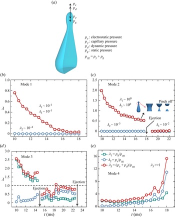
(a) Electrostatic pressure pe, capillary pressure pγ, dynamic pressure pd and static pressure pg at the droplet apex. Pressure variation in different ejection modes (b) mode 1, (c) mode 2, (d) mode 3, (e) mode 4. The data are acquired from simulations. (a) Schematic diagram of the pressure on the droplet apex, (b) mode 1 (We = 12.6, E = 1.3 kV cm−1), (c) mode 2 (We = 25.3, E = 1.3 kV cm−1), (d) mode 3 (We = 21.0, E = 4.3 kV cm−1) and (e) mode 4(We = 25.3, E = 6.0 kV cm−1).

In mode 1, as shown in figure 8(b), the order of magnitude of λ 2 is only 10−4, and the order of magnitude of λ 1 is 10−1, which indicates that both the electrostatic and dynamic pressures are much smaller than pγg, so no ejection can occur at the droplet apex. In mode 4, the order of λ 1 is approximately 1, while the order of λ 2 is approximately 10, and the growth rate of λ 2 is accelerated with the droplet stretching, which reflects that the electrostatic pressure greatly overcomes pγg in mode 4, and proves that the filamentous ejection is mainly caused by the strong electrostatic force. In figure 8(c), before droplet ejection, the electrostatic pressure pe is extremely weak, while the dynamic pressure pd is very close to the order of pγg. After the ejection, pd becomes too weak to form a subsequent ejection. Thus, the stretching kinetic energy can be considered to be the primary cause of ejection in mode 2. It is worth noting that, as shown in figure 8(c), either λ 1 or λ 3 could be greater than 1 when the droplet begins to stretch, but then gradually decreases to less than 1 until the ejection. It indicates the sum of the dynamic and electrostatic pressures during ejection in mode 2 is not sufficient to overcome pγg, but the droplet is still successfully ejected. The main reason is that when the stretching kinetic energy is large, a narrow throat, as shown in figure 8(c), appears at the front of the droplet. The fluid interface above the throat will generate a capillary force upward, while the interface below the throat will generate a downward capillary force, which can promote the fracture of the throat and then generate ejection (Ganan-Calvo et al. Reference Ganan-Calvo, Lopez-Herrera, Rebollo-Munoz and Montanero2016). Furthermore, the formation of the throat requires a certain amount of stretching kinetic energy to be converted into surface energy, so pd will be weakened in the stretching process. At this time, pd may not be enough to overcome pγg, but the appearance of the narrow throat will generate additional capillary forces to enable the droplet to successfully eject. In mode 3, before the first ejection, λ 1 is always greater than 1, indicating the dynamic pressure is enough to overcome pγg, prompting the first ejection. However, then, the dynamic pressure is significantly reduced due to the increase of surface energy, the order of λ 1 and λ 2 is only 10−1, but the sum of the two λ 3 is close to 1. It indicates that the subsequent ejection is mainly formed under the action of both electrostatic and dynamic pressures. However, λ 3 does not exceed 1, indicating that the sum of pd and pe does not exceed pγg. The reason for subsequent ejection is similar to that of mode 2, with additional capillary force in the liquid throat causing the ejection.
To sum up, in mode 1, the sum of the dynamic pressure pd and electrostatic pressure pe at the droplet apex is much less than pγg (the sum of the static pressure pg and capillary pressure pγ), and the droplet does not eject. In mode 4, because the electric field is strong enough that pe is much larger than pγg, the droplet is stretched into a filament and sprayed. In mode 2, the droplet has a moderate stretching kinetic energy and pd and pγg are of the same order of magnitude, so the droplet can be stretched to form a narrow throat, which then breaks to form a satellite droplet. In mode 3, after the droplet has undergone its first ejection, similar to that in mode 2, the combined pressure of pd and pe causes the primary droplet to significantly stretch and create a liquid throat, which then breaks to form a subsequent ejection.
3.3. Influence of impact Weber number on the four modes
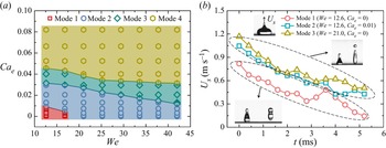
The impact Weber number (We) can strongly influence the droplet stretch morphology and inertia force (Yarin Reference Yarin2006), and coupled with the electrostatic force, We will inevitably have a greater impact on the impact ejection. Figure 9(a) shows the effect of We on the droplet ejection modes. It can be found that mode 1 only occurs under low Weber number and weak Cae, the weak inertial force and electrostatic force can keep the droplets from breakup and ejection. Mode 4 can occur at all Weber numbers but requires an extremely strong electric field. This is because the strong electrostatic force will overcome the liquid surface tension and droplet gravity to achieve filamentous stretching and ejection. Mode 2 can occur at slightly stronger electric field when We is less than 16.8, but it will occur at weaker Cae when We is greater than 16.8. If We is large, the impact kinetic energy is enough to cause the droplet to stretch and break up into a satellite droplet, but if We is small, the appropriate electrostatic force can compensate for the weak inertia force during the droplet stretching, thus ejecting a satellite droplet. Figure 9(b) compares the droplet stretching speed with and without an electric field. It can be observed that under the same We = 12.6, Cae = 0.001 can increase the stretching speed of droplets by approximately 50 % compared with no electric field (Cae = 0). Moreover, when We is 12.6 and Cae = 0.001 (mode 2), the stretching velocity of the droplet is very close to that when the We is 21.0 without an electric field (mode 2), which indicates that an appropriate electrostatic force can enhance the dynamic pressure of the droplet stretching and promote its transition from mode 1 to mode 2. Under a moderate electric field, in mode 3, the primary droplet after the first ejection will be subjected to a certain electrostatic force. Under the action of electrostatic force and inertia force, the droplet will continue to eject.
(a) Map showing the effect of Weber number on the droplet ejection modes. (Red-shaded region, mode 1; purple-shaded region, mode 2; green-shaded region, mode 3; yellow-shaded region, mode 4). (b) Droplet stretching speed Us for mode 1 and mode 2, both the enhancement of electric field and the increase of Weber number can promote the droplet stretching speed. This data are obtained from the experiments.

3.4. The charge scaling law of the ejection droplet
Previous studies have shown that when electrospray occurs, the formation time scale τf of the new free interface is almost equivalent to the charge induction time scale τe, because the charge balance at the Taylor cone should be maintained (Ganan-Calvo et al. Reference Ganan-Calvo, Lopez-Herrera, Rebollo-Munoz and Montanero2016). Therefore, the electric charge q 1 of the first ejection droplet is closely related to the physical parameters of the liquid fluid (density ρ 1, viscosity μ 1, surface tension γ, electrical conductivity σ 1 and electrical permittivity ε 1) and the physical parameters of the environment (electrical permittivity ε 2), i.e.  $q_1\sim \delta _u^{{-}2/3} \beta ^{7/12}q_0$, where
 $\delta _u = \rho _1d_0\nu _0/\mu _1$,
 $\beta = \varepsilon _1/\varepsilon _2$,
 $q_0 = \varepsilon _2E_0d_0^2 $,
 $\nu _0 = (\gamma \sigma _1/\rho _1\varepsilon _2)^{1/3}$,
 $E_0 = (\gamma /d_0\varepsilon _2)^{1/2}$ and
 $d_0 = (\gamma \varepsilon _2^2 /\rho _1\sigma _1^2 )^{1/3}$ (Ganan-Calvo et al. Reference Ganan-Calvo, Lopez-Herrera, Rebollo-Munoz and Montanero2016). In this study, τe can be thought of as the electric relaxation time, the conductivity σ 1 of deionized water is 10−5 S m−1 and the electrical permittivity ε 1 is
 $7 \times 10^{{-}10}\ {\rm F}\ {\rm m}^{-1}$ in numerical simulation, so
 $\tau _e = \varepsilon _1/\sigma _1 = 70\;{\rm \mu}{\rm s}$, and τf in filamentous ejection (mode 4) is approximately 50 μs. It can be found that τe and τf are of the same order of magnitude in mode 4, so the charge for the first ejection droplet in mode 4 should also apply to the equation above. In the numerical simulation, we found that the charge of the first ejection droplet in mode 4 is between 24.69 fC and 31.72 fC, which is consistent with the order of q 1 (11.93 fC) mentioned above.
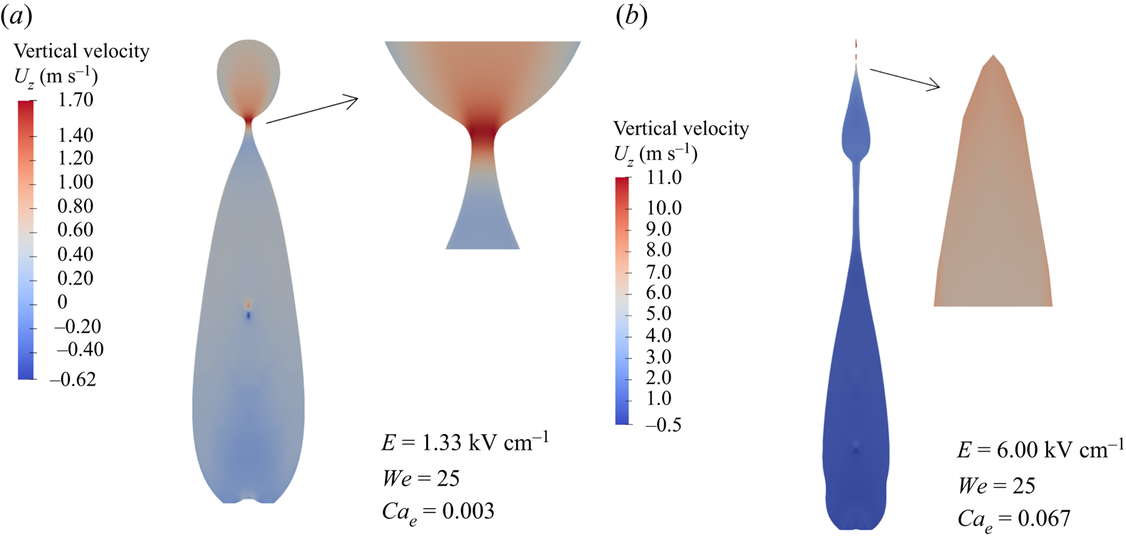
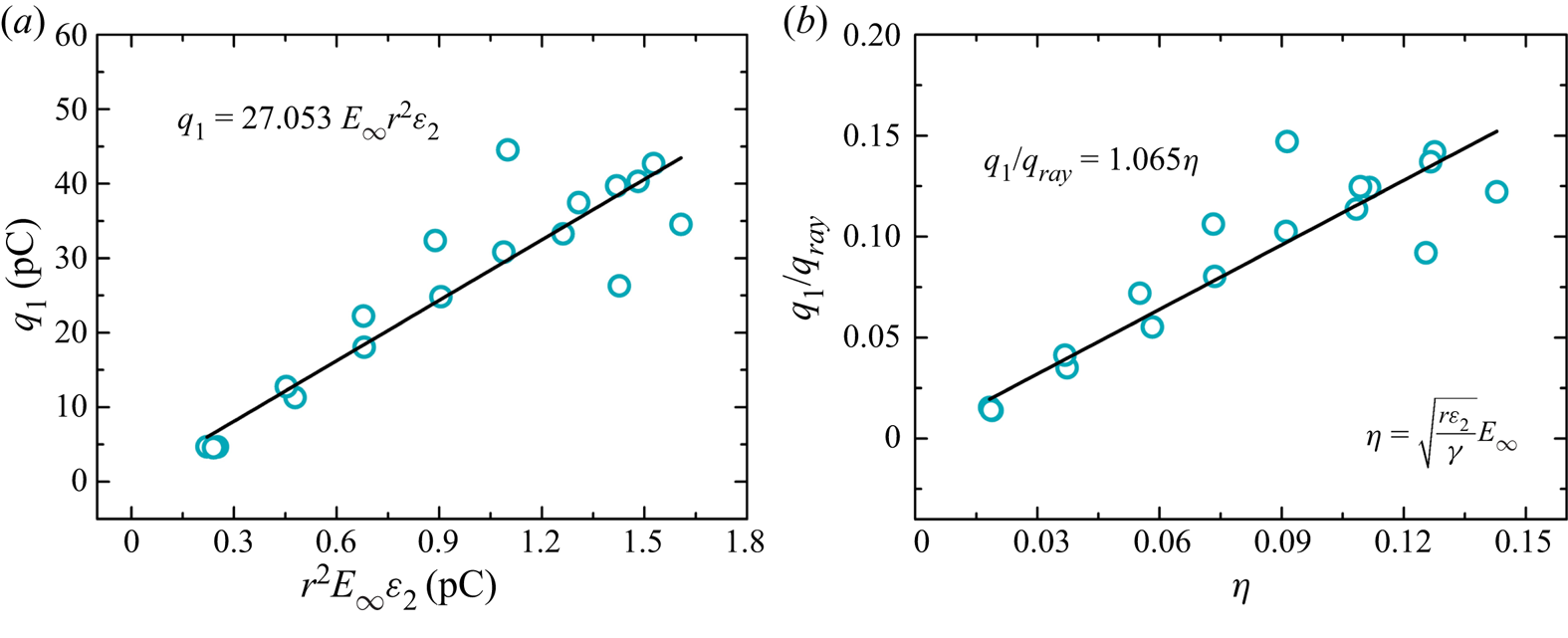
However, the charge mechanism in dropwise ejection (modes 2 and 3) is different from that of the electrospray. In figure 10, the flow velocity at the throat for dropwise ejection is one order of magnitude smaller than that of the filamentous ejection. Therefore, the droplet ejection in modes 2 and 3 is slower. The τf in modes 2 and 3 is approximately 2 ms, which is much larger than the time scale of charge induction τe = 70 μs, so the charge has enough time to reach a stable state on the surface of the ejection droplet. It can be speculated that the charge q 1 is proportional to the surface area of the ejection droplet and the applied electric field (Kim et al. Reference Kim, Im, Jung and Kang2007), considering dimensions,  $q_1\propto r^2\varepsilon _2E_\infty $, where r is the ejection droplet radius and E ∞ is the strength of the electric field applied. Figure 11(a) proves that q 1 in modes 2 and 3 is indeed proportional to the droplet surface area and applied electric field, and the proportional coefficient is approximately 27.053. For scaling analysis, the Rayleigh limit charge qray, the theoretical maximum charge of a droplet, is introduced. Given
 \begin{equation}q_{ray} = (8\varepsilon _2\gamma r^3)^{1/2},\quad q_1/q_{ray}\propto \eta = \sqrt {\displaystyle{{r\varepsilon _2} \over \gamma }} E_\infty .\end{equation}
Figure 11(b) shows the droplet charge q 1 relative to the Rayleigh limit qray as a function of η. The linear fit yields  $q_1/q_{ray} = 1.065\eta $.
Fluid vertical velocity of a stretch droplet (a) mode 2, (b) mode 4, where the flow rate of the necked fluid is very fast, which is an order of magnitude higher than that of the dropwise ejection.

(a) Relationship between the charge amount q 1 of the ejection droplet in modes 2 and 3 and the radius and applied electric field. (b) Ratio of q 1 to the Rayleigh limit qray versus η. The black solid line is the fit q 1/qray = 1.065η.

3.5. Theoretical models predict ejection modes
In this section, we will introduce the theoretical model for three ejection modes and predict the threshold electric field for different modes. In figure 7, under different electric fields, the stretching height and velocity of the droplet tend to be the same before 3 ms. At this moment, the droplet stretching is mainly dominated by the inertia force. After 3 ms, the inertia force is exhausted, and the electrostatic force plays a dominant role in the droplet stretching. Understandably, the inertial force is a volumetric force and the electrostatic force is only a surface force, so in the region of the inertial force, it must dominate the droplet stretching. It can be assumed that before the inertial force is completely dissipated, the height and morphology of the droplet are little affected by the electrostatic force, and are mainly affected by the Weber number of the droplet impact. Such an assumption is critical and reasonable. Obtaining the morphology of the droplet after stretching is the key to calculate the distorted electric field and electrostatic force near the droplet (Lozano et al. Reference Lozano, Martinez-Sanchez and Lopez-Urdiales2004). In other words, when the inertial force is exactly exhausted, to obtain the morphology of the stretched droplet more conveniently, the inertial force, viscous force and interfacial force will be considered, but the effect of the electrostatic force on the droplet morphology at this moment will not be involved.
The ejection after droplet impact occurs mainly at the apex, so the electric field near the apex is crucial. When the droplet is in a uniform electric field between two parallel electrode plates, the normal electric field En near its apex is (Lozano et al. Reference Lozano, Martinez-Sanchez and Lopez-Urdiales2004)
 \begin{equation}E_n = 1.4\displaystyle{{U_e} \over {r_m}}\left( {\displaystyle{{r_m} \over {2d-\varDelta H}}} \right)^{0.2},\end{equation}
where Ue is the applied voltage on the electrode, rm is the curvature radius at the apex of the droplet, d is the spacing of two parallel electrode plates and ΔH is the droplet height. Therefore, rm and ΔH are the key parameters to calculate the local electric field En at the droplet apex. According to the above analysis, the electrostatic force is the dominant factor of droplet stretching after the inertia region, and also determines the droplet ejection mode. When the inertia force is exactly completely dissipated, the electrostatic force at the droplet apex determines whether it can overcome the surface tension to produce filamentous ejection (mode 4), or whether it can continue to stretch and form enough kinetic energy to overcome the surface tension (mode 2 and mode 3). Therefore, we calculate En based on rm and ΔH when the inertial force is exactly exhausted. Fortunately, rm and ΔH are almost unaffected by the electric field, so rm and ΔH can be calculated based on the energy analysis for the droplet impact.
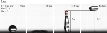
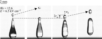
In figure 12, when the inertial force is exactly exhausted, the stretching height ΔH of the droplet can be approximated by the rebound height. This is because after the inertia region, the stretch kinetic energy of the droplet is almost zero, and it only relies on the release of surface energy to rebound (if the kinetic energy is strong enough, the ejection satellite droplet will carry kinetic energy, so that the stretch kinetic energy of the primary droplet can also be considered zero), so the rebound height could be the same as ΔH. The droplet will have kinetic energy  $E_{k0} = 1/2m_0u_0^2 $ and surface energy Es 0 when it starts to impact the substrate, where m 0 is the droplet initial mass and u 0 is the impact velocity. When it rebounds to the maximum height, the droplet will have surface energy Es 1. There should also be viscous dissipation ΔW and gravitational potential energy
 $m_0g\varDelta H$ during the whole impact process. Using the conservation of energy,
 \begin{equation}{\textstyle{1 \over 2}}m_0u_0^2 + E_{s0} = \varDelta W + m_0g\varDelta H + E_{s1},\end{equation}
the ejection satellite droplet is very small, and its kinetic energy is approximately 1/20 of the initial kinetic energy. Therefore, the kinetic energy carried by the ejection droplet is ignored. However, we can assume that the droplet remains spherical when it rebounds to maximum height, so the change in surface energy is negligible, given
 \begin{equation}\varDelta H = ({\textstyle{1 \over 2}}m_0u_0^2 -\varDelta W)/m_0g.\end{equation}
When the droplet spreads to the maximum area, the viscous dissipation of the whole spreading process can be expressed as (Hao et al. Reference Hao, Wang, Chen, Ma, Lan and Bai2018)
 \begin{equation}\varDelta W_1 = \displaystyle{{{\rm \pi} } \over 8}\mu _1u_0d_{max}^2 \sqrt {Re} ,\end{equation}
where Re is Reynolds number,  $Re = 2ru_0\rho _1/\mu _1$, and μ 1 is the viscosity of water fluid. Here dmax is the maximum spread diameter, which is given by (Hao et al. Reference Hao, Wang, Chen, Ma, Lan and Bai2018)
 \begin{equation}d_{max} = 2r\sqrt {\displaystyle{{We + 12} \over {3(1-\cos \theta ) + 4(We/\sqrt {Re} )}}} .\end{equation}
In this experiment, the total contact time between the droplet and the electrode plate is approximately 4.7 times of the spread time, so  $\varDelta W = 4.7\varDelta W_1$. Moreover, it can be assumed that the stretched droplet is approximately cylindrical, and according to the conservation of volume
 $4/3{{\rm \pi} }r^3 = {{\rm \pi} }r_m^2 \varDelta H$, rm can be obtained by
 \begin{equation}r_m = \sqrt {\displaystyle{{4r^3} \over {3\varDelta H}}} ,\end{equation}
where rm and ΔH can be determined from (3.6) and (3.9), so En can also be determined. However, the force mechanism of each ejection mode is different, so it is necessary to analyse the force conditions in each mode.
Curvature radius rm at the droplet apex and droplet height ΔH when the inertial force is exactly exhausted.

3.5.1. Mode 2
In mode 2, the droplet will not eject in the absence of an electric field, but could eject a satellite droplet in the presence of a moderate electric field. Based on the analysis of dynamic pressure and capillary pressure, we found that electrostatic force promotes the stretching kinetic energy of the droplet, causing the dynamic pressure to overcome the surface tension, thus forming the ejection droplet. We may assume that the stretch velocity required for dropwise ejection is u 2. In the critical state, the dynamic pressure should be equivalent to the capillary pressure, thus u 2 could be given by
 \begin{equation}\displaystyle{{2\gamma } \over {r_m}}\sim \displaystyle{1 \over 2}\rho _1u_2^2 ,\quad u_2\sim 2\sqrt {\displaystyle{\gamma \over {r_m\rho _1}}} .\end{equation}
When there is no electric field, the stretch kinetic energy will eventually be exhausted, but the electric field in mode 2 could slow down the reduction of the stretch speed, and eventually reach u 2 and ejection, so the work done by electrostatic pressure should be the kinetic energy of velocity u 2,
 \begin{equation}{\textstyle{1 \over 2}}\varepsilon _2E_n^2 \varDelta H\sim {\textstyle{1 \over 2}}\rho _1u_2^2 r_m.\end{equation}
Thus, En can be expressed by
 \begin{equation}1.4\displaystyle{{U_e} \over {r_m}}\left( {\displaystyle{{r_m} \over {2d-\varDelta H}}} \right)^{0.2}\sim E_n\sim 2\sqrt {\displaystyle{\gamma \over {\varepsilon _2\varDelta H}}} .\end{equation}
The threshold electric field E∞ for mode 2 can be given by
 \begin{equation}E_\infty = \displaystyle{{U_e} \over d} = 1.43\displaystyle{{r_m^{0.8} } \over d}\sqrt {\displaystyle{\gamma \over {\varepsilon _2\varDelta H}}} (2d-\varDelta H)^{0.2}.\end{equation}
So, the threshold electric capillary number Cae for mode 2 is
 \begin{equation}Ca_e = \displaystyle{{\varepsilon _2E_\infty ^2 r} \over \gamma } = 2.04\displaystyle{{r_m^{1.6} r} \over {d^2\varDelta H}}(2d-\varDelta H)^{0.4}.\end{equation}
3.5.2. Mode 3
In mode 3, the primary droplet could continue to eject after the first ejection. As shown in figure 13, after the primary droplet ejects for the first time, the stretch speed is very small, but the electrostatic force could promote the stretched droplet to reach u 2. At the critical state, the dynamic pressure and the capillary pressure are balanced, so u 2 also follows (3.10a,b) in mode 3. Furthermore, we assume that the height of the second ejection is the same as that of the first ejection, so the stretch distance of the primary droplet is approximately 2rm. Therefore, the work done by electrostatic pressure could be expressed by
 \begin{equation}{\textstyle{1 \over 2}}\varepsilon _2E_n^2 2r_m\sim {\textstyle{1 \over 2}}\rho _1u_2^2 r_m.\end{equation}
Combining (3.4), (3.10a,b) and (3.15), gives
 \begin{equation}1.4\displaystyle{{U_e} \over {r_m}}\left( {\displaystyle{{r_m} \over {2d-\varDelta H-2r_m}}} \right)^{0.2}\sim E_n\sim \sqrt {\displaystyle{{2\gamma } \over {\varepsilon _2r_m}}} .\end{equation}
The threshold electric field E ∞ for mode 3 can be expressed by
 \begin{equation}E_\infty = \displaystyle{{U_e} \over d} = 1.01\sqrt {\displaystyle{\gamma \over {\varepsilon _2}}} \displaystyle{{r_m^{0.3} } \over d}(2d-\varDelta H-2r_m)^{0.2}.\end{equation}
So, the threshold electric capillary number Cae for mode 3 is
 \begin{equation}Ca_e = \displaystyle{{\varepsilon _2E_\infty ^2 r} \over \gamma } = 1.02\displaystyle{{r_m^{0.6} r} \over {d^2}}(2d-\varDelta H-2r_m)^{0.4}.\end{equation}
Multiple dropwise ejection (mode 3). After the first ejection, the initial stretch velocity is very low, but the stretch velocity could gradually increase under the action of the electrostatic force.

3.5.3. Mode 4
In mode 4, the droplet shows a filamentous ejection due to the electrostatic pressure overcoming the capillary pressure. In the critical state, the two pressures are in equilibrium, which gives
 \begin{equation}\displaystyle{1 \over 2}\varepsilon _2E_n^2 \sim \displaystyle{{2\gamma } \over {r_m}}.\end{equation}
So En can be expressed by
 \begin{equation}1.4\displaystyle{{U_e} \over {r_m}}\left( {\displaystyle{{r_m} \over {2d-\varDelta H}}} \right)^{0.2}\sim E_n\sim 2\sqrt {\displaystyle{\gamma \over {\varepsilon _2r_m}}} .\end{equation}
The threshold electric field E ∞ for mode 4 can be given by
 \begin{equation}E_\infty = \displaystyle{{U_e} \over d} = 1.43\sqrt {\displaystyle{\gamma \over {\varepsilon _2}}} \displaystyle{{r_m^{0.3} } \over d}(2d-\varDelta H)^{0.2}.\end{equation}
So, the threshold electric capillary number Cae for mode 4 is
 \begin{equation}Ca_e = \displaystyle{{\varepsilon _2E_\infty ^2 r} \over \gamma } = 2.04\displaystyle{{r_m^{0.6} r} \over {d^2}}(2d-\varDelta H)^{0.4}.\end{equation}
In summary, the threshold electric capillary number Cae for the three different ejection modes is
 \begin{equation}
Ca_e = \left\{
\begin{array}{@{}ll}
2.04\displaystyle{{r_m^{1.6} r} \over {d^2\varDelta H}}(2d-\varDelta H)^{0.4},\;{\rm mode}\; 2,\\
1.02\displaystyle{{r_m^{0.6} r} \over {d^2}}(2d-\varDelta H-2r_m)^{0.4},\;{\rm mode}\; 3 \\
2.04\displaystyle{{r_m^{0.6} r} \over {d^2}}(2d-\varDelta H)^{0.4},\;{\rm mode}\; 4, \end{array}
\right.\!\!\!\!,\end{equation}
where 2d − ΔH is of the order of several centimetres, and 2rm is of the order of 10−1 millimetres, thus  $2d-\varDelta H-2r_m$ can be approximated by 2d − ΔH. Combining (3.9), (3.14), (3.18) and (3.22), we can obtain the ratio of threshold Cae for the three modes:
 \begin{equation}Ca_e^{{\rm mode}\; 2} {\rm :\ }Ca_e^{{\rm mode}\; 3} {\rm :\ }Ca_e^{{\rm mode}\; 4} = 2.32\left( {\displaystyle{r \over {\varDelta H}}} \right)^{1.5}{\rm :}1{\rm :}2.\end{equation}
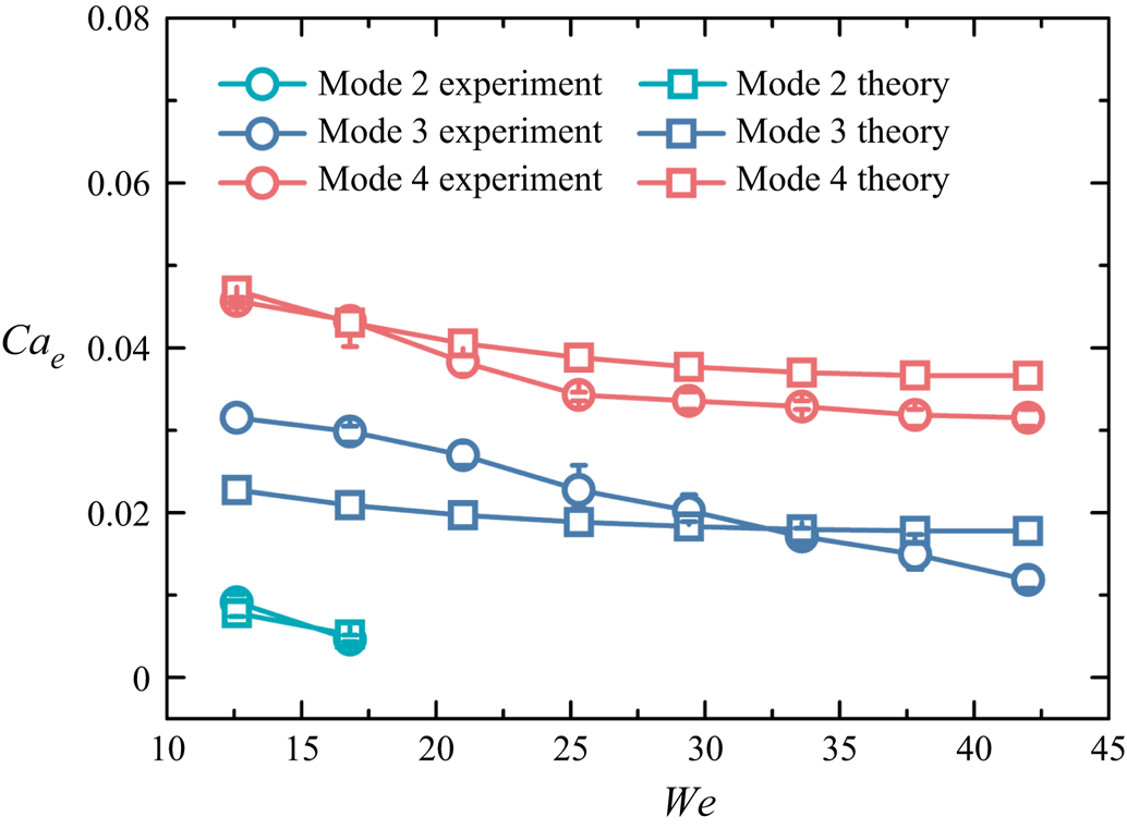
Figure 14 shows a comparison for the experimental and theoretical threshold Cae for the three ejection modes. With the increase of impact Weber number, the overall trend for Cae is in good agreement, and the maximum error is less than 26 %. It proves that our theoretical model can accurately predict different ejection modes. We believe that such theoretical analysis will contribute to further reveal the effect mechanism of the electric field on droplet impact.
Theoretical and experimental comparison for threshold Cae in different ejection modes.

3.6. The rebound behaviour of droplets after impact
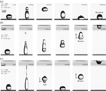
Whether the droplet remains on the substrate after impact will have an important effect on the complete transport of the droplet or the self-clean. In this section, we will discuss the behaviour of retention or bounce after impact under an electric field. Figure 15 shows the droplet in three different states after impact. When the droplet is ejected, the primary droplet may fall back and remain on the substrate, a state that is named retention (figure 15a). It is also possible for the primary droplet to jump and approach the upper electrode without falling, a behaviour that is named bounce (figure 15b). Interestingly, under certain experimental conditions, the primary droplet may fall, but upon recontact with the electrode, it will quickly bounce and accelerate its motion towards the upper electrode, an interesting dynamic behaviour that is named fall–bounce (figure 15c). Retention droplets will remain on the SH surface forever unless the environment is sufficiently disturbed. It is worth noting that the liquid–solid contact time is the shortest in bounce, only approximately 17.80 ms. However, in fall–bounce, the droplet will contact the electrode twice, so the solid–liquid contact time is approximately 34.20 ms. The bounce dynamic provides a new design idea for the electric field promoting surface cleaning.
Dynamic behaviors of droplets after ejection. (a) The droplet eventually remains on the substrate. (b) The droplet can jump from the substrate without falling. (c) The droplet can fall and impact on the substrate, and then jump again without falling. This data was obtained from the experiments. (a) Retention, (b) bounce and (c) fall–bounce.

Previous studies have shown that when droplet impacts, fluid may enter the microstructure, which will make the superhydrophobic surface fail and change from a Cassie–Baxter state to a Wenzel state (Lee et al. Reference Lee, Nam, Lastakowski, Hur, Shin, Biance, Pirat, Kim and Ybert2015). In the retention mode, the droplets repeatedly bounce on the surface several times before becoming stationary, which fully indicates that our superhydrophobic surface has not failed and is still in a Cassie–Baxter state. The main reason for the droplet retention is because the electrostatic force cannot overcome gravity.
Whether the electrostatic force can overcome the primary droplet gravity should be the key to determine whether droplet retention and the electric charge of the droplet can significantly affect the electrostatic force. In this experiment, when the droplet is ejected, the satellite droplets can carry a large amount of charge and separate out, resulting in a significant reduction in the charge of the primary droplet. When the satellite droplet carries less charge or the primary droplet carries more charge, the electrostatic force is strong enough to overcome gravity, so the primary droplet can bounce quickly without falling back (i.e. bounce). When the primary droplet has a small amount of charge, it will fall back and contact with the electrode again. Such a contact process causes the droplet to regain a certain amount of inductive charge, and if the electrostatic force generated by the inductive charge is enough to overcome gravity, it will bounce (i.e. fall–bounce), but if the electrostatic force is weaker than gravity, it will remain on the electrode surface (i.e. retention).
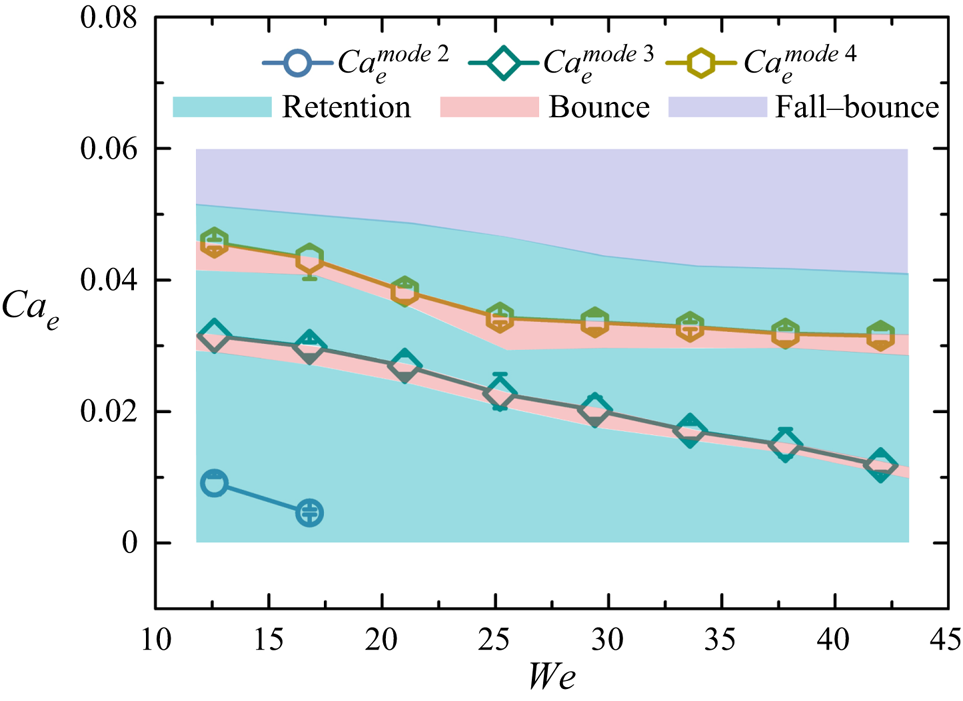
The size and number of satellite droplets in the four ejection modes are different, carrying different amounts of electric charge. Thus, the ejection modes should affect the bounce or fall of the primary droplet. Figure 16 shows the occurrence conditions of retention, bounce and fall–bounce, and the threshold electric field Et of the ejection modes. Here, Et 3 and Et 4 represent the threshold electric field of mode 3 and mode 4, respectively. We can observe that fall–bounce occurs in mode 4. The filamentous ejection can produce many charged satellite droplets, which will reduce the charge amount of the primary droplet, the electrostatic force cannot overcome the gravity, and the droplet will fall back. However, the electric field in mode 4 is very strong. After the droplet is recharged, it will obtain an electrostatic force sufficient to overcome gravity. Therefore, the droplet can bounce and accelerate upward movement.
A mapping is produced to show the region of retention, bounce, fall–bounce. (Blue-shaded region, retention; pink-shaded region, bounce; purple-shaded region, fall–bounce),  $Ca_e^{mode\;2} $, threshold electric capillary number for ejection mode 2;
 $Ca_e^{mode\;3} $, threshold capillary number for ejection mode 3;
 $Ca_e^{mode\;4} $, threshold electric capillary number for ejection mode 4. The electric field for bounce is slightly less than Et 3 and Et 4. This data was obtained from the experiments.

Interestingly, bounce, the behaviour of the droplet jumping without falling, does not occur when the electric field is at its strongest. As shown in figure 16, bounce occurs in electric field ranges slightly less than Et 3 and Et 4. In the same ejection mode, the dynamic behaviour of the ejection is almost the same. Only one satellite droplet will be sprayed in mode 2, two in mode 3, and one filament will be sprayed in mode 4, with the largest number of satellite droplets. In mode 2 or mode 3, the electric charge separated from the satellite droplets is not as much as in mode 4, and as the electric field increases, the electrostatic force on the primary droplet will exceed gravity, so the droplet bounces and does not fall. However, as soon as the droplet transitions from mode 2 to mode 3, or from mode 3 to mode 4, the droplet loses a lot of charge from the ejection, so the primary droplet stays on the electrode.
For the physics problem in this study, inertial force, electric force and surface tension are the most critical forces, and the impact Weber number We and electric capillary number Cae basically involve these three forces. These two dimensionless parameters also involve the radius of the droplet, so theoretically, many droplet sizes can be applicable to the modes influenced by these two parameters. However, the experiment and simulation in this study are based on the premise that the electric relaxation time is much smaller than the impact characteristic time. The scale of impact characteristic time  $\tau _f\sim (\rho _1r^3/\gamma )^{1/2}$ (Li et al. Reference Li, Lin, Wang, Yuan, Joo and Chen2020), where ρ 1 is the density of liquid droplet. Suppose that the impact characteristic time
 $\tau _f$ is an order of magnitude larger than the electric relaxation time
 $\tau _e,\tau _f\sim 10\tau _e$, then the radius r is calculated to be approximately 330 μm. Therefore, the droplet with a radius greater than 330 μm may be applicable to the mode in this study.
4. Conclusion
We have studied the ejection and rebound dynamics of a droplet impacting a superhydrophobic surface under an electric field using experiments and numerical simulation, and discovered the filamentous ejection phenomenon after droplet impact for the first time. When the droplet is stretched vertically upward, the electric charge accumulates at the droplet apex, where the electric field is stronger. After stretching, the droplet exhibits four different ejection modes. The forces on the droplet apex determine the mode of ejection. In mode 1, the electrostatic pressure pe and dynamic pressure pd cannot overcome the combined pressure pγg of capillary and static pressures. In mode 2, the order of magnitude of pd is the same as pγg, and under the action of dynamic pressure, a throat will be formed and gradually be pinched off. In mode 3, the first ejection is due to the dynamic pressure overcoming pγg, and then pd and pe will cause the primary droplet to stretch and form a subsequent ejection. In mode 4, the electrostatic pressure pe will far exceed pγg, and the electrostatic force will also exceed the droplet gravity, so it could quickly be stretched into a liquid filament and sprayed. A theoretical model was established based on the energy equation and force mechanism, which can predict the threshold electric field of droplet ejection with a maximum error of less than 26 %. In addition, in dropwise ejection, the new free interface is formed slowly, and the ejection droplets are fully charged. Therefore, the charged amount of the ejection droplets is proportional to the surface area and electric field, and the charge scaling law is proposed. The satellite droplets can carry a certain amount of electric charge, which reduces the charge of the primary droplet. The primary droplet will exhibit three different rebound behaviours after ejection due to the different electrostatic forces. Our research has an important guiding value for the design of droplet-based electrically controlled equipment, as well as for surface self-cleaning and electrospray printing.
Supplemental material
Supplementary material are available at https://doi.org/10.1017/jfm.2022.234.
Acknowledgements
We would like to thank four anonymous referees for their valuable comments, which were very helpful for the scale analysis of § 3.5.
Funding
This research was supported by National Natural Science Foundation of China (no. 52176056) and National Natural Science Foundation of China Innovation Research Group Project (no. 52021004).
Declaration of interests
The authors report no conflict of interest.