1. Introduction
Hydraulic joint robots, such as bipedal hydraulic robots [1–Reference Feng, Feng, Xinjilefu, Atkeson and Kim3], quadruped hydraulic robots [Reference Semini, Tsagarakis, Guglielmino, Focchi and Cannella4–Reference Guizzo8], and multi-degree of freedom hydraulic manipulators [Reference Lin, Lin, Ren, Chen, Li and Chen9], have been proposed. The motion of joint robots essentially comes from the rotation of joints driven by joint actuators. Therefore, hydraulic joint actuators with the following characteristics are necessary: compact size, high power density, low internal leakage, low starting pressure, and low weight. Especially for joint robots moving in the field, improving the power density and reducing the weight of joint actuators are of great significance to their endurance and load capacity.
Hyon et al. built a biped humanoid robot called TAEMUT [1] with 13 joints using linear hydraulic actuators (HyAs) and four-bar linkage. Its structure was inspired by the SARCOS humanoid robot [Reference Cheng, Hyon, Morimoto, Ude, Colvin, Scroggin and Jacobsen2] developed by Cheng et al. The famous Boston Dynamics biped robots, PETMAN and Atlas, are also driven by a linear hydraulic driver and linkage mechanism [Reference Feng, Feng, Xinjilefu, Atkeson and Kim3]. The dynamic legged Systems Laboratory of the Italian Institute of Technology presented the HyQ series of quadruped robots, which were built with linear HyAs and connecting rod mechanisms [Reference Semini, Tsagarakis, Guglielmino, Focchi and Cannella4–Reference Barasuol, Villarreal-Magaña, Sangiah, Frigerio, Baker, Morgan, Medrano-Cerda, Caldwell and Semini6]. The early quadruped robots developed by Boston Dynamics also used hydraulic linear actuators and connecting rod mechanism in joints [Reference Sapaty7, Reference Guizzo8]. The excavator with which we are familiar is a typical manipulator system composed of a linear hydraulic driver and multi-link mechanical system [Reference Lin, Lin, Ren, Chen, Li and Chen9, Reference Feng, Yin, Weng, Ma, Zhou, Jia and Zhang10].
Although linear HyAs have good characteristics, such as low internal leakage, low starting pressure, and light weight, the application of linear HyAs in robot joints requires conversion mechanisms such as connecting rod mechanisms and curve mechanisms to convert the output linear motion and force into rotating motion and torque to drive the joint motion. However, the conversion mechanisms will lead to the following problems: (1) there is a mechanical gap in the conversion mechanisms when the movement is reversed, which may lead to violent collisions, thereby reducing the motion accuracy and increasing the energy consumption; (2) there is an increase in the joint weight and size, and the components in the conversion mechanisms will increase the complexity and weight of the joint; (3) an increase in the nonlinear torque occurs, where different parts in the conversion mechanisms move around the hinge point, which will increase the nonlinear friction torque; (4) the various parameters of conversion mechanisms are difficult to design, such as four-bar linkage, which has four-link lengths and four hinge point coordinate parameters [Reference Ba, Song, Yu, Wang, Li, Zhang and Ma11]; and (5) they have a variable transmission ratio, which is a characteristic of the linkage mechanism, which will increase the work of calculating joint torque in real time. Furthermore, a variable transmission ratio brings difficulties to the design of the control algorithm, especially for algorithms based on torque control.
Therefore, different forms of direct-drive HyAs have gradually been applied in joint robots. For example, direct-drive rotary HyAs were applied in HyQ-real, which is a newly developed robot of the Italian Institute of Technology [Reference Barasuol, Villarreal-Magaña, Sangiah, Frigerio, Baker, Morgan, Medrano-Cerda, Caldwell and Semini6]. The high-performance quadruped robot WildCat of Boston dynamics also uses rotary HyAs for the hip joint. Similarly, rotary HyAs are applied to Atlas. However, according to [Reference Barasuol, Villarreal-Magaña, Sangiah, Frigerio, Baker, Morgan, Medrano-Cerda, Caldwell and Semini6], the internal leakage of HyQ-real’s custom rotary actuator can be as high as 220 mL/min at 200 bar. Similarly, the leakage of rotary actuators developed by the KNR [Reference Kim, Lee, Shin, Lee, Park and Ahn12] company is not small. The existence of leakages will cause serious heating of the hydraulic oil, which increases energy consumption and reduces the actual output speed. At the same time, the torque to weight ratio of both rotary actuators is not optimistic. The highest torque to weight ratio in KNR’s commercial rotary actuator products is about 83 Nm/kg, and that of the custom rotary actuator applied in HyQ-real is only 80.96 Nm/kg.
It is worth noting that at present, HyAs that can directly convert the liquid pressure and flow of hydraulic oil into the output mechanical rotary motion and torque do so in the form of vanes [Reference Nikas, Burridge and Sayles13–Reference Xie and Luo15]. Other forms of lightweight rotary HyAs have been studied from many aspects [Reference Hyon, Yoneda and Suewaka16–Reference Boaventura, Buchli, Semini and Caldwell21], but they essentially convert linear motion and force into output rotational motion and torque through specific mechanisms [Reference Dellon22, Reference Yang, Guo, Yang and Xu23].
The remainder of this paper is organized as follows. In Section 2, we present the biological inspiration of HyA structure and the cross-design strategy for solving the design problem with multiparameter constraints. In Section 3, manufacture strategy and mechanical analysis of main parts of the HyA are introduced. In Section 4, dynamics model is established, and simple control strategies of the HyA are proposed based on the dynamics model. The experimental setup and results have been provided in Section 5. Conclusions are presented in Section 6.
2. Mechanical of the HyA
2.1. Bionic inspiration and conceptual design
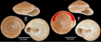
A snail’s body can extend clockwise (as shown by the red arrow in Fig. 1 [Reference Sutcharit, Thach, Chhuoy, Ngor, Jeratthitikul, Siriwut, Srisonchai, Ng, Pholyotha, Jirapatrasilp and Panha24]) or retract counterclockwise along the spiral line of the shell. From the perspective of mechanical kinematics, the movement of the snail’s body is an approximate swing movement guided along the spiral line. Inspired by this, we propose a HyA, whose output movement is similar to that of a snail’s body.

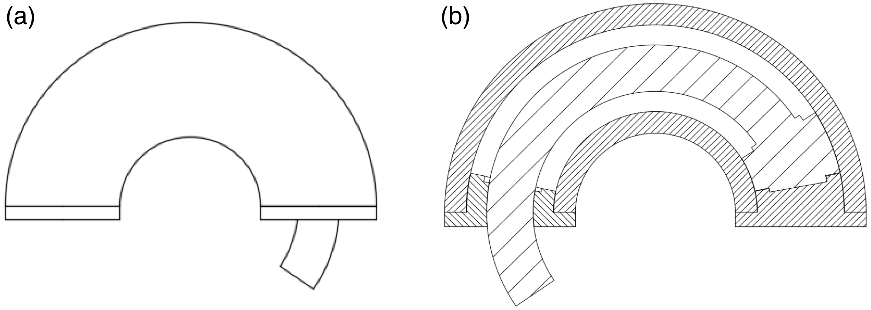
The HyA has a structure similar to that of a snail. First, the HyA has an arc shell, inspired by the snail shell. It has a closed reference end, inspired by the closed center point of the snail’s shell, and has a movable rod, inspired by the snail’s body. It also contains an open end to provide telescopic space, which was inspired by the opening of the snail’s shell. In Fig. 2, we have depicted an outline drawing (Fig. 2(a)) and an internal drawing (Fig. 2(b)) of the conceptual design of the HyA.
Conceptual design of the HyA.

2.2. Motion of the HyA
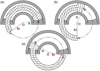
First, the centerline of the movable rod coincides with that of the arc shell, as shown in Fig. 3. The force generated by the hydraulic oil acting on the big head of the movable rod pushes the R line to rotate around point O. In other words, the movable rod is pushed by the hydraulic oil in the arc shell to produce circular motion, as shown in Fig. 3. The sequence of motion is (a)→(b)→(c). From the other side, the force generated by the hydraulic oil acts on the Rr line by the movable rod, equivalently, and pushes the Rr line to rotate around point O uniformly, as shown in Fig. 3.
Movement of the HyA.

The motion analysis tells us that the hydraulic oil will directly push the Rr line to rotate around point O, that is, there is no conversion mechanism, just like a vane hydraulic swing cylinder. The Rr line is designed as a torsion arm that connects point A with point O. Finally, we designed a shaft at point O, which outputs outward rotational motion.
2.3. Design parameters and cross-design strategy
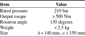
The main parameters of the HyA are shown in Table I.
Main parameters of the HyA.

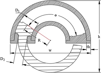
Some mechanical dimensions are described in Fig. 4.
Mechanical dimensions of the HyA.
 $D_{1}$
, diameter of big head of movable rod;
 $D_{2}$
, diameter of small head of movable rod;
 $R$
, radius of HyA; th, thickness of the arc shell.

The output torque,
 $T_{o}$
, of the HyA can be expressed by Eq. (1):
 \begin{equation}T_{o}=P_{s}\left(\int _{R-\frac{D_{1}}{2}}^{R-\frac{D_{2}}{2}}f_{1}\!\left(r\right)dr+\int _{R-\frac{D_{2}}{2}}^{R}f_{2}\!\left(r\right)dr+\int _{R}^{R+\frac{D_{2}}{2}}f_{3}\!\left(r\right)dr+\int _{R+\frac{D_{2}}{2}}^{R+\frac{D_{1}}{2}}f_{4}\!\left(r\right)dr\right)\end{equation}
where
 $f_{1}\!\left(r\right)=2r\sqrt{\frac{D_{1}^{2}}{4}-\left(R-r\right)^{2}}$
,
 $f_{2}\!\left(r\right)=2r\sqrt{\frac{D_{1}^{2}}{4}-\left(R-r\right)^{2}}-2r\sqrt{\frac{D_{2}^{2}}{4}-\left(R-r\right)^{2}}$
,
 $f_{3}\!\left(r\right)=2r\sqrt{\frac{D_{1}^{2}}{4}-\left(r-R\right)^{2}}-2r\sqrt{\frac{D_{2}^{2}}{4}-\left(r-R\right)^{2}}$
,
 $f_{4}\!\left(r\right)=2r\sqrt{\frac{D_{1}^{2}}{4}-\left(r-R\right)^{2}}$
,
 $P_{s}$
is the rated pressure, and
 $r$
is the integral variable.
We can see that Eq. (1) is too complex for analytical calculation. The pressure acts uniformly on the surface; we can consider that the hydraulic oil pressure acting on the head of the movable rod is equivalent to a concentrated force. Therefore, we can simplify Eqs. (1) to (2) as:
 \begin{equation}T_{o}\approx \frac{\pi }{4}P_{s}R\left(D_{1}^{2}-D_{2}^{2}\right)\end{equation}
Considering the reduction of weight and the convenience of manufacturing, we chose 7075 aluminum alloy to manufacture the arc shell.
 $th$
can be described by Eq. (3) as:
 \begin{equation}th=\frac{\varphi P_{s}D_{1}}{\left(2.3\left[\sigma \right]-P_{s}\right)}\end{equation}
where
 $[\sigma ]$
is the allowable stress of the material (in this work it is
 $82\text{ MPa}$
), and
 $\varphi$
is the structural safety factor, which is
 $\varphi =2$
in this study.
Finally, we can get the cross constraints, that is, the torque constraints and dimensional constraints (i.e., height and width) as described by Eqs. (4), (5) and (6), respectively, as:
 \begin{equation}500\text{ Nm} < \mathrm{T}_{\mathrm{o}} < 550\text{ Nm}\end{equation}
 \begin{equation}h=\frac{D_{2}}{2}+2R+\frac{D_{1}}{2}+th\lt 140\text{ mm}\end{equation}
 \begin{equation}w=2\mathrm{*}R+D_{1}+2th\lt 150\text{ mm}\end{equation}
where reasonable parameter ranges of each are
 \begin{equation*}D_{1}\epsilon (25\,{\rm mm}, 32\,{\rm mm}),D_{2}\epsilon (12\,{\rm mm}, 18\,{\rm mm}),R\epsilon (45\,{\rm mm}, 52\,{\rm mm}).\end{equation*}
Then, we traverse the space,
 $D_{1}$
,
 $D_{2}$
, and
 $R$
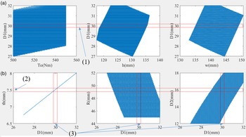
, with a step size of 0.05 mm to obtain the values that meet the constraints. The traversal results are shown in Fig. 5.
Cross-design strategy.

The cross-design strategy is based on the selection of the data point density in a reasonable numerical region in constraint space, so as to make the design parameters more reasonable.
As can be seen from the traversal results, the density of data points that meet the constraints near
 $D_{1}=30\,\textrm{mm}$
is large (Fig. 5(a)), so we chose 30 mm as the final size of
 $D_{1}$
. Then, we used rectangle (1) to cover the area around
 $D_{1}=30$
mm in Fig. 5(a), and rectangle (3) to cover the area around
 $D_{1}=30$
mm in Fig. 5(b). We drew a rectangle (2) and moved it along the coordinates in Fig. 5(b). Finally, we can see that in the subgraph of
 $th$
vs.
 $D_{1}$
, the overlap between rectangle (2) and rectangle (3) is a maximum near the region
 $th=7.5$
mm. Meanwhile, we can also get the appropriate values of
 $R$
and
 $D_{2}$
, that is,
 $R=50$
mm and
 $D_{2}=16\text{ mm}$
. Under this condition, the minimum output torque of the HyA is 531.1 Nm, the size of h is 130.5 mm, and w is 145 mm.
3. Manufacture strategy and mechanical analysis
3.1. Manufacture strategy of the arc shell
Manufacturing diagram of the HyA.

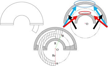
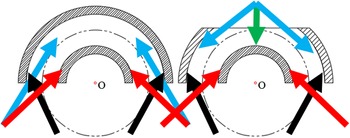
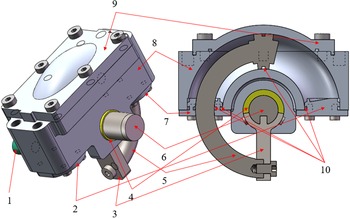
After conceptual and parameter design, we found that there was a major manufacturing problem in the detailed design, whereby the inner surface of the arc shell could not be machined by a milling machine in some places, as shown in the blue circle and red circle areas of Fig. 6. The red, blue, and black arrows in Fig. 6 represent the milling cutter feed path. Thus, we devised a split manufacturing strategy, as shown in Fig. 7(b), where we divided the arc shell into upper and lower parts, and then manufactured them separately. Figure 7(b) shows the manufacturing process of the lower part, where the red, blue, black, and green arrows represent the milling cutter feed path. Finally, bolts were used to assemble the upper and lower parts together. Figure 8 shows a 3D diagram of the HyA.
Splitting manufacturing strategy diagram.

3D diagram of the HyA. 1: Hydraulic oil port, 2: back cover, 3: swing bar, 4: sliding bar, 5: movable rod, 6: shaft, 7: front cover, 8: lower housing, 9: upper housing, and 10: sealings.

We have listed a comparison of the HyA and other rotary HyAs in Table II. It can be seen that the torque to weight ratio of our HyA is almost three times that of other products, which means that the weight of a robot joints with the HyA will be greatly reduced. In addition, the HyA can provide a greater joint rotation angle than the other products.
3.2. Mechanical analysis
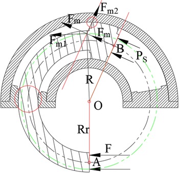
The movable rod is subjected to the pressure of the hydraulic oil and completes circular motion under the constraint of the arc shell. An external force also acts on the movable rod, suggesting that the force environment of the movable rod is extreme. Here, we carried out a force analysis of the movable rod. As shown in Fig. 9, the hydraulic oil pressure,
 $P_{s}=21$
MPa, acts on the B plane of the movable rod, where
 $F_{m}$
is the equivalent force of
 $P_{s}$
. We decomposed
 $F_{m}$
into
 $F_{m1}$
and
 $F_{m2}$
, where
 $F_{m1}$
pushes the movable rod to rotate and
 $F_{m2}$
pushes the movable rod to squeeze the arc shell, which will produce extrusion stress and sliding friction, as shown in the small red circle in Fig. 9. Similarly, extrusion stress and sliding friction will also occur in the big red circled area in Fig. 9.
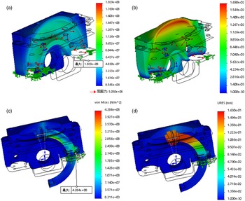
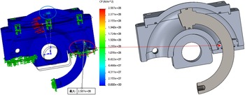
We used the finite element method to conduct a finite element analysis, which is used to calculate the stress and deformation in detail. The results are shown in Fig. 10. The results show that the maximum stress of the arc shell (7075 aluminum alloy) and movable rod (40Cr) is under the maximum stress that the material can withstand. The total deformation of the arc shell and movable rod is small. Figure 10 also shows the extrusion stress between the movable rod and arc shell. The maximum extrusion stress was 258.7 MPa, which occurs in the contact area between the front cover and the movable rod. Into this area, we inserted a sealing groove, which leads to a reduction in the contact area between the front cover and the movable rod. The blue circle area of Fig. 11 shows the contact between the movable rod and arc shell, where the extrusion stress of this area was almost 100 MPa. The extrusion stress, shown in the blue and red circles of Fig. 11, is moderately large, and there is contact sliding friction. Therefore, we considered anodizing the inner surface of the arc shell to increase its hardness and wear resistance and treated the front cover the same way. Meanwhile, we treated the surface of the movable rod with nitridation technique.
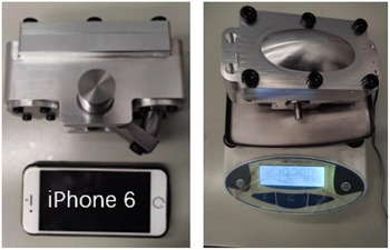
Finally, the assembled HyA is shown in Fig. 12, and the weight of the HyA is 1.93 kg.
4. Dynamics model and simple control strategy of the HyA
4.1. Dynamics model of the HyA
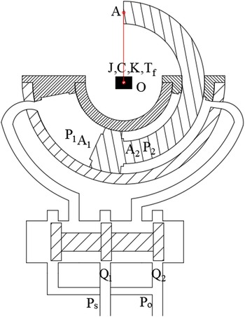
Like other HyAs, the HyA is controlled by a servo valve to realize servo control, as shown in Fig 13. We establish the dynamic model of the servo valve controlling HyA. First, we make the following assumptions: (1) all connecting pipelines are short and thick, and the hydraulic oil weight, friction pressure loss, and pipeline dynamics are ignored; (2) the hydraulic oil flows evenly, and the oil temperature and elastic modulus are constant; and (3) the external leakage is zero, and the internal leakage is a laminar flow.
Comparison of HyA and other rotary HyAs.

Force analysis of the HyA.

We divide the dynamics model into two parts according to the right and left movement of the servo valve core. The core of the servo valve moves to the right (
 $X_{v}\gt 0$
), which leads to the movable rod extending counterclockwise. The hydraulic oil flows through servo valve
 $q_{r1}$
, and
 $q_{r2}$
is equal to that flowing into the two cavities of the HyA, that is,
 $q_{1l}$
and
 $q_{2l}$
.
 $q_{r1}$
and
 $q_{r2}$
can be described by Eq. (7):
 \begin{align}\begin{cases} q_{r1}=C_{d}wX_{v}\sqrt{\dfrac{2}{\rho }\left(P_{s}-P_{1}\right)}\\[14pt] q_{r2}=C_{d}wX_{v}\sqrt{\dfrac{2}{\rho }P_{2}} \end{cases}\end{align}
where
 $C_{d}$
is the flow coefficient of the servo valve,
 $w$
is the area gradient of the servo valve,
 $X_{v}$
is the displacement of the servo valve core,
 $\rho$
is the hydraulic oil density,
 $P_{1}$
is the pressure acting on the big head of the movable rod, and
 $P_{2}$
is the pressure acting on the small head of the movable rod.
 $q_{1l}$
and
 $q_{2l}$
can be obtained from the volume conservation of hydraulic oil, as described by Eq. (8):
 \begin{align}\begin{cases} q_{1l}=C_{i}\!\left(P_{1}-P_{2}\right)+\dfrac{V_{1}}{\beta _{e}}\dfrac{dP_{1}}{dt}+\dfrac{dV_{1}}{dt}\\[15pt] q_{2l}=C_{i}\!\left(P_{1}-P_{2}\right)-\dfrac{V_{2}}{\beta _{e}}\dfrac{dP_{2}}{dt}+\dfrac{dV_{2}}{dt} \end{cases}\end{align}
where
 $C_{i}$
is the internal leakage coefficient,
 $V_{1}$
is the cavity volume of the big head of the movable rod,
 $V_{2}$
is the cavity volume of the small head of the movable rod, and
 $\beta _{e}$
is the elastic modulus of the hydraulic oil.
The volume,
 $\textit{V}$
, of the hydraulic oil of the arc shell can be described by Eq. (9):
 \begin{equation}V=AR\theta\end{equation}
where
 $\theta$
is the rotation angle.
Finite element analysis results of arc shell and moveable rod. (a) Total stress of the arc shell, (b) total deformation of the arc shell, (c) total stress of the movable rod, and (d) total deformation of the movable rod, all at 210 bar.

Finite element analysis results of the extrusion stress between the arc shell and moveable rod.

Assembled HyA.

Dynamic model of the servo valve controlling the HyA.

By combining the above equations, we can get Eq. (10):
 \begin{align}\begin{cases} q_{1l}=C_{i}\left(P_{1}-P_{2}\right)+\dfrac{V_{1}}{\beta _{e}}\dfrac{dP_{1}}{dt}+A_{1}R\dfrac{d\theta }{dt}\\[12pt] q_{2l}=C_{i}\left(P_{1}-P_{2}\right)-\dfrac{V_{2}}{\beta _{e}}\dfrac{dP_{2}}{dt}+A_{2}R\dfrac{d\theta }{dt} \end{cases}\end{align}
where
 $A_{1}$
is the area of the big head of the movable rod and
 $A_{2}$
is the area of the small head of the movable rod.
Next, we set
 $V_{1}=V_{2}=V_{0}$
, where
 $V_{0}$
is the half total volume of the arc shell. Then, we define the load flow,
 $Q_{L1}$
(Eq. (11)) and the load pressure,
 $P_{L}$
, (Eq. (12)) as:
 \begin{equation}Q_{L1}=\frac{q_{1}+nq_{2}}{1+n^{2}}\end{equation}
 \begin{equation}P_{L}=\frac{T_{ow}}{A_{1}}=R\left(P_{1}-nP_{2}\right)\end{equation}
where
 $n=\dfrac{A_{2}}{A_{1}}$
and
 $T_{ow}$
is the output torque of the shaft.
Then, by combining the various terms, we get Eq. (13):
 \begin{equation}Q_{L1}=\frac{C_{i}\left(P_{1}-P_{2}\right)\left(1+n\right)}{1+n^{2}}+A_{1}R\frac{d\theta }{dt}+\frac{V_{0}}{R\beta _{e}\left(1+n^{2}\right)}\frac{dP_{L}}{dt}\end{equation}
Similarly, we deduce
 $q_{l1}$
,
 $q_{l2}$
, and
 $Q_{L2}$
when the servo valve core moves to the left (
 $X_{v}\lt 0$
), and the movable rod of the HyA retracts clockwise as:
 \begin{align}\begin{cases} q_{l1}=C_{d}wX_{v}\sqrt{\dfrac{2}{\rho }P_{1}} \\[14pt] q_{l2}=C_{d}wX_{v}\sqrt{\dfrac{2}{\rho }\left(P_{s}-P_{2}\right)} \end{cases}\end{align}
 \begin{equation}Q_{L2}=\frac{C_{i}\left(P_{1}-P_{2}\right)\left(1+n\right)}{1+n^{2}}+A_{1}R\frac{d\theta }{dt}-\frac{V_{0}}{R\beta _{e}\left(1+n^{2}\right)}\frac{dP_{L}}{dt}\end{equation}
If we linearize
 $Q_{L1}$
and
 $Q_{L2}$
, we get Eq. (16):
 \begin{equation}Q_{L}=\begin{cases} Q_{L1}=q_{r1}=K_{q}X_{v}-K_{c}P_{L}\\[5pt] Q_{L2}=q_{l2}=K_{q}^{i}X_{v}-K_{c}^{i}P_{L} \end{cases}\end{equation}
where
 $K_{rq}=C_{d}w\sqrt{\frac{2}{\left(1+n^{3}\right)\rho }\left(P_{S}-\frac{P_{L}}{R}\right)}$
,
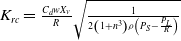 $K_{rc}=\frac{C_{d}wX_{v}}{R}\sqrt{\frac{1}{2\left(1+n^{3}\right)\rho \left(P_{S}-\frac{P_{L}}{R}\right)}}$
,
 $K_{lq}=C_{d}w\sqrt{\frac{2}{\left(1+n^{3}\right)\rho }\left(nP_{S}+\frac{P_{L}}{R}\right)}$
, and
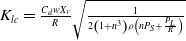 $K_{lc}=\frac{C_{d}wX_{v}}{R}\sqrt{\frac{1}{2\left(1+n^{3}\right)\rho \left(nP_{S}+\frac{P_{L}}{R}\right)}}$
.
The load balance equation is described as Eq. (17):
 \begin{equation}P_{L}A_{1}R=J\frac{d^{2}\theta }{dt}+C\frac{d\theta }{dt}+K\theta +T_{f}\end{equation}
where
 $J$
is the equivalent inertia,
 $C$
is the equivalent damping,
 $K$
is the equivalent spring stiffness,
 $T_{f}$
is the equivalent load torque, and
 $\theta$
is the rotation angle.
Next, we combine Eqs. (8), (10), (13), (15), (16), and (17) and perform a Laplace transform on them. Finally, we get Eq. (18):
 \begin{align} \begin{cases} {\unicode[Arial]{x03B8}} _{r}=\dfrac{A_{1}K_{rq}X_{v}-T_{f}\left(\dfrac{V_{0}}{R\beta _{e}\left(1+n^{2}\right)}S+\dfrac{1+n}{1+n^{3}}\dfrac{C_{i}}{R}+K_{rc}\right)}{k_{a1}S^{3}+k_{a2}S^{2}+k_{a3}S+k_{a4}},X_{v}\gt 0\\[12pt] {\unicode[Arial]{x03B8}} _{l}=\dfrac{A_{1}K_{lq}X_{v}-T_{f}\left(\dfrac{V_{0}}{R\beta _{e}\left(1+n^{2}\right)}S+\dfrac{1+n}{1+n^{3}}\dfrac{C_{i}}{R}+K_{lc}\right)}{k_{a11}S^{3}+k_{a22}S^{2}+k_{a33}S+k_{a44}},X_{v}\lt 0 \end{cases}\end{align}
where
 $k_{a1}=k_{a11}=\frac{V_{0}}{R\beta _{e}\left(1+n^{2}\right)}J$
,
 $k_{a2}=\frac{1+n}{1+n^{3}}\frac{C_{i}}{R}J+K_{rc}J+\frac{V_{0}C}{R\beta _{e}\left(1+n^{2}\right)}$
,
 $k_{a22}=\frac{1+n}{1+n^{3}}\frac{C_{i}}{R}J+K_{lc}J+\frac{V_{0}C}{R\beta _{e}\left(1+n^{2}\right)}$
,
 $k_{a3}=\frac{V_{0}K}{R\beta _{e}\left(1+n^{2}\right)}+\frac{1+n}{1+n^{3}}\frac{C_{i}}{R}C+K_{rc}C+A_{1}^{2}R$
,
 $k_{a33}=\frac{V_{0}K}{R\beta _{e}\left(1+n^{2}\right)}+\frac{1+n}{1+n^{3}}\frac{C_{i}}{R}C+K_{lc}C+A_{1}^{2}R$
,
 $k_{a4}=\frac{1+n}{1+n^{3}}\frac{C_{i}}{R}K+K_{rc}K$
,
 $k_{a44}=\frac{1+n}{1+n^{3}}\frac{C_{i}}{R}K+K_{lc}K$
, and
 $S$
is the Laplace operator.
When
 $C, K$
can be neglected, Eq. (18) is simplified to the standard Eq. (19). Note that Eq. (19) only describes the dynamics of the case
 $V_{1}=V_{2}=V_{0}$
, which makes it sufficient to design the control algorithm:
 \begin{align} \begin{cases} {\unicode[Arial]{x03B8}} _{r}=\dfrac{A_{1}K_{rq}X_{v}-T_{f}\left(\dfrac{V_{0}}{R\beta _{e}\left(1+n^{2}\right)}S+\dfrac{1+n}{1+n^{3}}\dfrac{C_{i}}{R}+\dfrac{C_{e}}{1+n^{2}}\dfrac{1}{R}+K_{c}\right)}{S\left(\dfrac{S^{2}}{w_{h1}^{2}}+\dfrac{2\varepsilon _{h1}}{w_{h1}}S+1\right)},X_{v}\gt 0\\[30pt] {\unicode[Arial]{x03B8}} _{l}=\dfrac{A_{1}K_{lq}X_{v}-T_{f}\left(\dfrac{V_{0}}{R\beta _{e}\left(1+n^{2}\right)}S+\dfrac{1+n}{1+n^{3}}\dfrac{C_{i}}{R}+\dfrac{C_{e}}{1+n^{2}}\dfrac{1}{R}+K_{c1}\right)}{S\left(\dfrac{S^{2}}{w_{h2}^{2}}+\dfrac{2\varepsilon _{h2}}{w_{h2}}S+1\right)},X_{v}\lt 0 \end{cases}\end{align}
where
 $w_{h1}=w_{h2}=\sqrt{\frac{k_{a3}}{k_{a1}}}=\sqrt{\frac{k_{a33}}{k_{a11}}}=\sqrt{\frac{R\beta _{e}\left(1+n^{2}\right)\left(A_{1}^{2}R\right)}{V_{0}J}}$
,
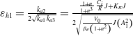 $\varepsilon _{h1}=\frac{k_{a2}}{2\sqrt{k_{a1}k_{a3}}}=\frac{\frac{1+n}{1+n^{3}}\frac{C_{i}}{R}J+K_{rc}J}{2\sqrt{\frac{V_{0}}{\beta _{e}\left(1+n^{2}\right)}J\left(A_{1}^{2}\right)}}$
, and
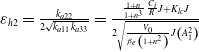 $\varepsilon _{h2}=\frac{k_{a22}}{2\sqrt{k_{a11}k_{a33}}}=\frac{\frac{1+n}{1+n^{3}}\frac{C_{i}}{R}J+K_{lc}J}{2\sqrt{\frac{V_{0}}{\beta _{e}\left(1+n^{2}\right)}J\left(A_{1}^{2}\right)}}$
.
We can get the minimum natural frequency,
 $w_{h\min }$
, of the HyA control system from Eq. (19), as described as Eq. (20), where
 $\theta$
is the maximum rotation angle of the HyA:
 \begin{equation}w_{h\min }=\left(1+\sqrt{n}\right)\sqrt{\frac{RA_{1}\beta _{e}}{J\theta }}\end{equation}
Equation (20) tells us that the minimum natural frequency of the HyA control system is affected by the parameters
 $R, A_{1},A_{2}, \beta _{e},\theta$
, and
 $\textit{J}$
. So, we can increase the natural frequency by increasing the mechanical parameters of
 $R, A_{1},A_{2}$
and reduce the parameters of
 $J$
and
 $\theta$
, which will increase the response speed of the HyA control system.
The stability of the HyA control system is affected by the parameters
 $\varepsilon _{h1}$
and
 $\varepsilon _{h2}$
. We can see that
 $\varepsilon _{h1}$
and
 $\varepsilon _{h2}$
are affected by
 $A_{1},A_{2},C_{i},K_{rc}$
, and
 $K_{lc}$
so that we can appropriately increase the internal leakage by the mechanical design to increase the stability of the HyA control system. But, doing so will increase the energy consumption of the system. Therefore, we can design a control algorithm to ensure the stability of the HyA control system.
Similarly, we can deduce the output torque (Eq. (21)) of the HyA under the condition of
 $C, K\approx 0$
. It can be seen that Eq. (21) has similar properties to Eq. (19). In other words, we can design similar control algorithms for the position control and torque control for the HyA as:
 \begin{align}\begin{cases} \mathrm{T}_{r}=JS^{2}{\unicode[Arial]{x03B8}} _{r}+\mathrm{T}_{f}\\[5pt] \mathrm{T}_{l}=JS^{2}{\unicode[Arial]{x03B8}} _{l}+\mathrm{T}_{f} \end{cases}\end{align}
4.2. Design of the position control and torque control algorithms
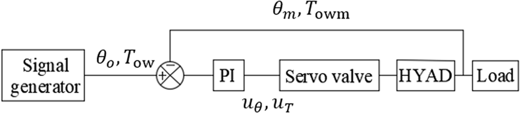
Equations (19) and (21) have similar transfer function forms. We design a simple proportional integral (PI) controller using classical control theory, described as Eqs. (22) and (23):
 \begin{equation}u_{\theta }=K_{p}\left(\theta _{o}-\theta _{m}\right)+K_{i}\int \left(\theta _{o}-\theta _{m}\right)\end{equation}
 \begin{equation}u_{T}=K_{Tp}\left(T_{ow}-T_{owm}\right)+K_{Ti}\int \left(T_{ow}-T_{owm}\right)\end{equation}
where
 $u_{\theta }$
is the control input of the position control of the HyA,
 $u_{T}$
is the control input of the torque control of the HyA,
 $K_{p}$
is the scale factor of the PI position controller of the HyA,
 $K_{Tp}$
is the scale factor of the PI torque controller of the HyA,
 $K_{i}$
is the integral coefficient of the PI position controller of the HyA,
 $K_{Ti}$
is the integral coefficient of the PI torque controller of the HyA,
 $\theta _{o}$
is the expectation angle of the shaft,
 $\theta _{m}$
is the measured angle of the shaft,
 $T_{ow}$
is the expectation torque of the shaft, and
 $T_{owm}$
is the measured torque of the shaft.
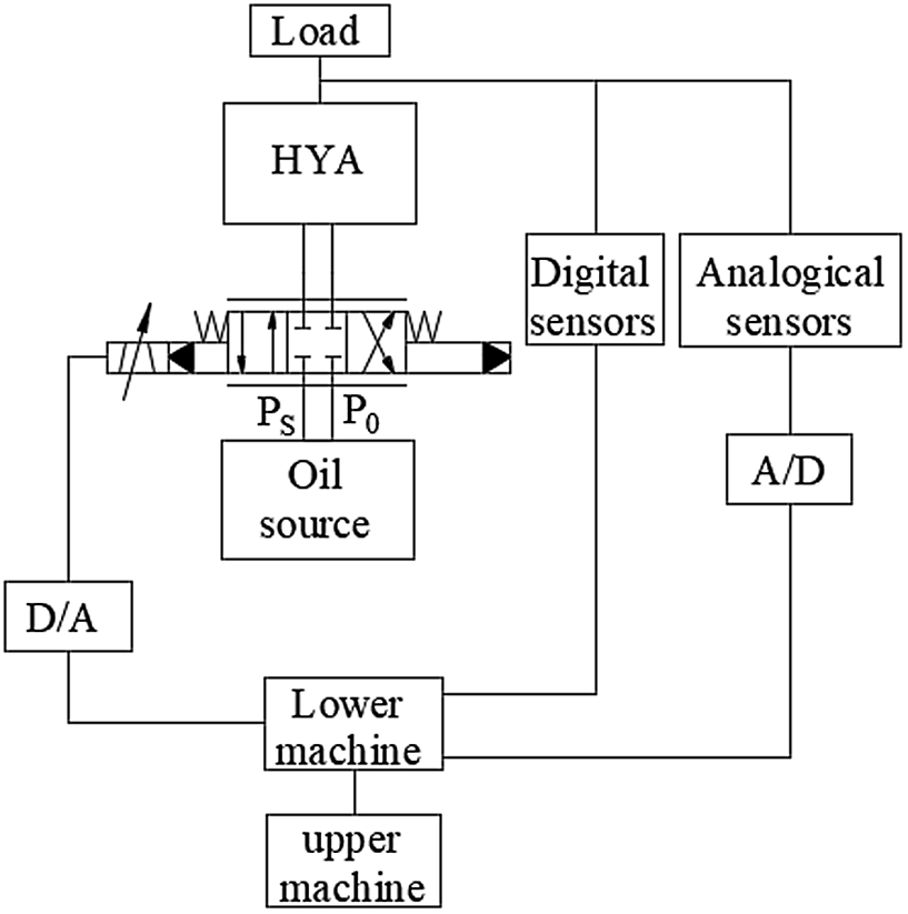
Figure 14 shows the structure of the control system of the HyA, and Fig. 15 shows the control diagram of the HyA with the PI controller.
Structure of the control system of the HyA.

Control diagram of the HyA with the PI controller.

Basic test system for the HyA.

5. Experiments and results
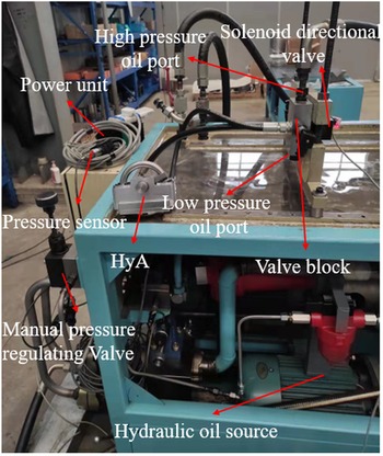
The basic test system used for HyA is shown in Fig. 16, which is mainly composed of a power unit, pressure sensor, manual pressure regulating valve, hydraulic oil source, valve block, and solenoid directional valve. We can adjust the input pressure of HyA by the manual pressure regulating valve and change the movement direction of HyA by the solenoid directional valve. In the following subsection, some of our experimental results are presented.
5.1. Starting pressure experiment
We tested the starting pressure of the HyA in two movement directions; the results are shown in Table III.
We can see from Table III that the starting pressure of extending movement is smaller than that of retracting movement, which is caused by the area of the big head of the moveable rod being larger than that of the small head of the moveable rod. The average starting pressure of extending movement is 0.26 MPa, and that of retracting movement is 0.39 MPa. The rated pressure of the HyA is 21 MPa, and the percentage of the starting pressure in the two movement directions to the rated pressure is 1.24% and 1.86%, which indicates that the starting pressure in the two movement directions is very small.
Results of the starting pressure test.

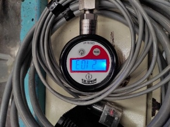
Pressure sensor.

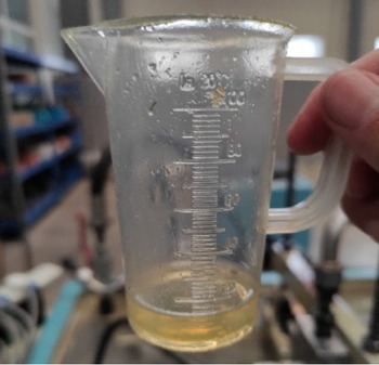
Hydraulic oil in the measuring cup.

5.2. Rated pressure
We adjusted the manual pressure regulating valve to make the pressure of the HyA reach 210 bar, as shown in Fig. 17. Under this condition, the HyA could swing normally without external leakage, which shows that the HyA can work normally under the rated pressure.
Results of the internal leakage test of the HyA.

Movement test of the HyA.

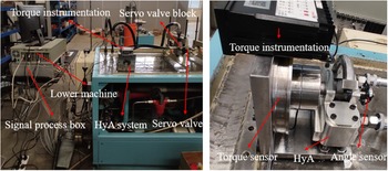
HyA servo experimental system.

5.3. Leakage
In order to test the internal leakage of the HyA, we exposed the low pressure oil port, as shown in Fig. 16. A timer and measuring cup were used to measure the internal leakage of HyA under the rated pressure of 210 bar, as shown in Fig. 18. The measurement results are shown in Table IV. The leakage recorded in Table IV was timed for 90 s. Figure 18 shows an example measurement. Since the seal on the movable rod is a two-way seal, there is a very little difference in the internal leakage of the movable rod when extending and retracting, with average leakages of 8.8 mL/min and 9 mL/min, respectively. It can be seen that the internal leakage of the HyA was very small, which can be considered as effectively negligible. We observed by a visual inspection that there was no external hydraulic oil leakage of the HyA at 210 bar, which indicated that the external leakage was zero.
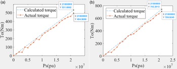
Output torque of the HyA under different pressures. (a) Output torque of the HyA when retracting and (b) output of the HyA when extending.

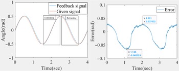
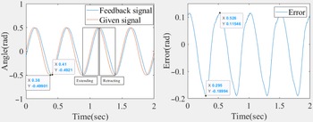
Results of 0.5 Hz sinusoidal signal tracking.

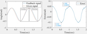
Results of 1 Hz sinusoidal signal tracking.

5.4. Movement
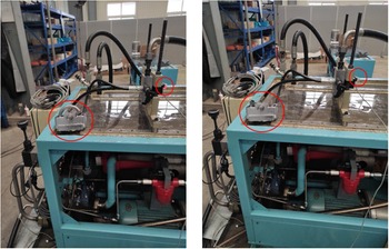
We switched the solenoid directional valve to change the movement direction of the HyA, as shown in Fig. 19. The HyA extended when the indicator light on the solenoid directional valve was on, and retracted when the indicator light on solenoid directional valve was off, as shown by the small red circle in Fig. 19. The movements of the HyA are as shown in the big red circle in Fig. 19. In testing the HyA’s movement, the moveable rod of the HyA was pushed by the hydraulic oil to move smoothly, which made the shaft rotate.
5.5. Servo control
We established a HyA servo experimental system based on the principle shown in Fig. 14, as displayed in Fig. 20. As we could not produce a suitable torque load, we simply tested the static output torque of the HyA under different pressures and measured the subsequent positions of the HyA servo.
Results of 2 Hz sinusoidal signal tracking.

We can see from Fig. 21 that the actual output torque of the HyA is less than the calculated torque, and there are fluctuations in the actual output torque. At the maximum output torque, the error is about 7.3% in the retraction direction and 4.5% in the extending direction. As shown in the mechanical analysis in Section 3.2, there is sliding friction between the movable rod and the arc shell, which makes the actual output torque of the HyA less than the calculated torque. We also found that the pressure of the oil source was unstable, and we were unable to keep the pressure stable by adjusting the manual pressure regulating valve, which makes the actual output torque of the HyA fluctuate.
Next, we carried out sinusoidal tracking experiments. The results, as shown in Figs. 22, 23, and 24, show that there is a phase difference at different frequencies, and the phase difference increased with an increase of frequency, 6.84 degrees at 0.5 Hz, 11.16 degrees at 1 Hz, and 19.44 degrees at 2 Hz. The phase difference in the retraction direction is larger than that in the extension direction, which is caused by the difference between
 $K_{rq}$
and
 $K_{lq}$
in Eq. (19). When a phase difference is not considered, the amplitude tracking error is very small, 0.8% at 0.5 Hz, 1% at 1 Hz, and 1.5% at 2 Hz.
6. Conclusions and future prospects
Inspired by the snail’s shell, the structure of HyA is proposed in this work. In the parameter design of the HyA, we provide a method based on density of data points to solve the multi-constraint design problem, named the cross-design method. A split manufacturing strategy is proposed to solve the manufacturing problem of the closed inner surface of the arc shell. Based on a mechanical analysis of the movable rod and arc shell, we reveal the contact stress and sliding friction between the movable rod and the shell. Furthermore, the stress and deformation are analyzed in detail by using the finite element method. Some surface treatment methods are put forward to solve the contact stress and sliding friction problem. A dynamic model of the servo valve controlled HyA is established, and some suggestions for improving the performance of the HyA control system are given in the mechanical design. Finally, simple PI controllers are proposed to realize output angle control and output torque control of the HyA based on the characteristics of the dynamic model.
Some experiments were carried out to verify the basic performance of the HyA. The results show that the HyA had a compact size, low starting pressure, low internal leakage, zero external leakage, low weight, and high torque to weight ratio, which will provide better performance to the robot joints systems.
In future work, we will study better position control algorithms to achieve better tracking performance, rather than simply using a PI controller. A joint leg system or arm system will be established, and the HyA will be applied to the system to further study torque control.
Acknowledgements
We thank International Science Editing (http://www.internationalscienceediting.com) for editing this article.
Author contributions
Jiaqi Li contributed to the conception of the study, performed the data analyses, and wrote the manuscript;
Dacheng Cong contributed significantly to analysis and manuscript preparation;
Yu Yang and ZhiDong Yang helped perform the analysis with constructive discussions.
Financial support
There is no financial support for this work.
Conflicts of interest
We declare that we do not have any commercial or associative interest that represents a conflict of interest in connection with the work submitted.
Ethical considerations
This article does not contain any studies with human participants or animals performed by any of the authors.