1. INTRODUCTION
Mechatronic system design is complex because it involves knowledge of different domains, including the mechanical, electrical, control, and software domains. To cope with these difficulties, systems engineering emerges as a viable alternative, as it takes a holistic view of the system (Weilkiens, Reference Weilkiens2011). Recently, model-based systems engineering has become a mainstream system design approach.
The system architecture is the core of mechatronic system design, as it reflects the results of early design decisions and is also the basis of other system-level work (system optimization, system simulation, etc.) and subsequent detail design. Therefore, the modeling language employed for the system architecture should be strong enough to model the architecture and its related work.
However, some deficiencies in the existing modeling languages remain. The first deficiency is the lack of approximate geometry and spatial relation information, which is necessary for subsequent detail design. The second is the lack of hybrid behavior description to support dynamic system simulation. The third is the lack of association semantics between different modeling elements that can support automated system design.
In this study, a Systems Modeling Language (SysML) based extension named ArchME is proposed for complex mechatronic system architecture modeling. SysML is a standard modeling language for model-based systems engineering proposed by the International Council on Systems Engineering and the Object Management Group in 2006 (Weilkiens, Reference Weilkiens2011). Similar to Unified Modeling Language (UML; Weilkiens, Reference Weilkiens2011), it has strong extensibility and thus has been chosen as the basis of ArchME. This paper is organized as follows. Work related to system architecture modeling is discussed in Section 2. Section 3 analyzes the requirements for architecture modeling languages. Section 4 elaborates on the architecture modeling elements. ArchME is described in Section 5. Section 6 illustrates the implementation of ArchME with a case study. Section 7 presents the conclusion and future work.
2. RELATED WORK
2.1. Studies on system architecture
Researchers define the term system architecture in different ways. According to Ulrich, the architecture consists of an arrangement of functional elements, that is, the function structure; mapping from functional elements to components (or design elements); and the specification of the interfaces between interacting components (Ulrich, Reference Ulrich1995). Ulrich further defined product architecture, and provided a typology for it. He also articulated the potential linkages between product architecture and other areas (e.g., product change, product variety, component standardization, product performance, and product development management). However, he did not comprehensively address how to model the specific system architecture. Clements argued that the architecture of a system is the components that comprise a system, the behavioral specifications for those components, and the patterns and mechanisms for interaction among them (Clements, Reference Clements1996). Preliminary results of Clements's survey outlined what constitutes an architecture description language and indicated how contemporary architecture description languages differ from each other. However, the specific subject matter of architecture modeling was not addressed. In Crawley's opinion, system architecture is an abstract description of the entities of a system and the relationships between them (Crawley et al., Reference Crawley, de Weck, Eppinger, Magee, Moses, Seering, Schindall, Wallae and Whitney2004). Crawley identified the influence of architecture in engineering systems, but introduced no knowledge regarding architecture modeling. Recently, Komoto and Tomiyama (Reference Komoto, Mishima and Tomiyama2012) also proposed an architecture model for mechatronic systems that supports system decomposition and defines the specifications of subsystems and interfaces. However, the emphasis of his work is computational support for the design of system architecture. Cabrera noted that the system architecture of a mechatronic system should convey what the main parts of the product are and what they do individually and as a group (Cabrera et al., Reference Cabrera, Woestenenk and Tomiyama2011). He provided an architecture model to support cooperative design for mechatronic products, but hybrid behavior and geometry information were studied less extensively. Generally, system architecture includes logical system architecture (the function layer) and physical system architecture (the component layer), and system architecting is an indispensable part of system design and represents the transformation from an abstract system function to detailed physical components. Effecting this transformation automatically is necessary with the growth in system complexity. Automation can be supported with ArchME.
2.2. Studies on modeling languages
As a standard system modeling language, SysML supports the entire system design process from requirement specification to validation. It is a general purpose modeling language that includes unambiguous descriptive semantics. Therefore, it can be used as a common communication platform between stakeholders from different domains. To enrich it with execution semantics from a specific area, most studies have extended it by using the top-down approach (Berkenkötter et al., Reference Berkenkötter, Bisanz, Hannemann and Peleska2006). However, the spatial structure of a system cannot be modeled by SysML. The internal block diagram in SysML can only represent the connection relationship between components (Lenny, Reference Lenny2013). Although SysML has a behavior diagram, there is still no uniform behavior modeling framework (Cao et al., Reference Cao, Liu, Fan and Fan2013).
The Architecture Analysis and Design Language (AADL) proposed by Feiler et al. (Reference Feiler, Gluch and Hudak2006) is a modeling language that was originally designed for avionics; it has been standardized by the Society of Automotive Engineers and can be used to describe both software execution platforms and the physical environments of embedded software systems. Moreover, AADL supports early prediction and analysis of nonfunctional properties, such as performance and reliability. A system is abstracted by AADL by describing its components, their interfaces, and the connectors between interfaces. AADL is especially effective for model-based analysis and specification of complex real-time embedded systems. However, some elements in mechatronic system design, such as the function element, structure element, and behavior element, are not involved.
ExSAM was proposed by Behjati et al. (Reference Behjati, Yue, Nejati, Briand and Selic2011). A combination of the architecture design and analysis concepts of AADL and the system modeling concepts of SysML, ExSAM introduces missing features from AADL into SysML. Therefore, it offers the benefits of both languages, and can specify embedded systems at different abstraction levels and from different stakeholder perspectives. However, it still lacks the necessary elements for modeling geometry and physical information.
Uniform Behavior Modeling Language (UBML) is proposed as a SysML profile to enable systems engineers to define behavioral requirements uniformly and help automate mapping from the design model to the simulation model (Cao et al., Reference Cao, Liu, Fan and Fan2013). However, its purpose is to support dynamic simulation, and it lacks basic architecture modeling elements (e.g., the function element).
The above analysis indicates that there is no architecture modeling language specific to the mechatronic system that supports its specific application such as dynamic simulation and detail design.
3. REQUIREMENT ANALYSIS FOR ARCHITECTURE MODELING
3.1. Context analysis of an architecture model
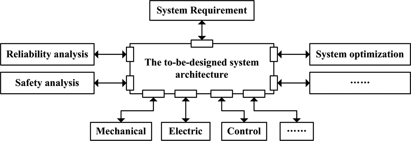
Before establishing an architecture model, it is necessary to analyze its context, that is, the factors it should communicate with. The architectural context diagram is proposed to make the communication relationship clear. As shown in Figure 1, the objects or subsystems that interact with the system architecture can be divided into the following categories:
-
1. The upstream system requirement: This is the starting point of system design. Each requirement should be satisfied, and any changes should be reflected in the system immediately.
-
2. Sibling operations: Because the system architecture is important to the entire mechatronic system design process, it is necessary to develop a series of related analysis and optimization operations to analyze and optimize the system architecture from different perspectives, for example, cost analysis, reliability analysis, security analysis, simulation analysis, and system optimization.
-
3. Downstream detail design: As previously mentioned, the system architecture is located in the middle of the system requirements and detail design. Therefore, it must contain enough unambiguous information to support the subsequent detail design.
Each external entity communicates with the system architecture through an interface that is depicted as a rectangle in Figure 1.
Architecture context diagram.

3.2. Fundamental elements of system architecture
Based on the analysis above, the following elements should be defined in the system architecture:
-
1. Function: It is the composition of the logical system architecture that is the medium of the user requirement and the physical component. However, there is no uniform, precise definition for it thus far although it is important for complex products. Researchers have different understandings based on a variety of views. Eisenbart et al. (Reference Eisenbart, Blessing and Gericke2012) concluded that the number of function models oriented to the mechanical, electrical, software, mechatronic, and service systems are 24, 8, 12, 10, and 16, respectively. These function models are generally divided into three categories: equipment based, process based, and functional concept based. The process-based function model is mainly used in the electrical domain, while the other two are used in the majority of domains (Eisenbart et al., Reference Eisenbart, Gericke and Blessing2013). In this study, for the convenience of automatic operation and function reuse, the definition proposed by Pahl and Beitz (Reference Pahl and Beitz2007) is used, whereby a function is regarded as the conversion from a specific input flow to a specific output flow. According to functional basis (Hirtz et al., Reference Hirtz, Stone, McAdams, Szykman and Wood2002), the type of a flow may be material, energy, signal, and their subtypes. Moreover, a function is completed by a series of processes that can be physical, chemical, or biological. Here, only the physical processes in mechatronic engineering are considered. A specific physical process may be realized by one or more specific working principles, which is composed of the physical effect, the material, and geometric properties (Pahl & Beitz, Reference Pahl and Beitz2007).
-
2. Structure: This is a physical system architecture whose basic element is a component. Given the complexity of the mechatronic system, the structure must have the following characteristics:
-
a. Hierarchy: According to Ulrich (Reference Ulrich1995), the function structure can be created at different levels of abstraction. Corresponding to the function, the structure should have different levels of description to make it easy to understand and organize.
-
b. Locality: As stated in Ulrich (Reference Ulrich1995), there are two types of architecture: modular architecture and integral architecture. The former includes a one-to-one mapping from the functional elements in the function structure to the physical components of the product and specifies decoupled interfaces between components. The latter includes a complex (non-one-to-one) mapping from the functional elements to the physical components and coupled interfaces between components.
-
c. Consistency: the complex mechatronic system involves subsystems of different domains. Uniform structure modeling is necessary to ensure the representation is consistent.
-
-
3. Behavior: The components are associated with each other following certain space relationships and behave in a predefined way to realize the specific function. The behavior model is important to verify the correctness of the complex mechatronic system. In the Oxford English Dictionary (Burchfield, Reference Burchfield1982), behavior is “the manner in which a thing acts under specified conditions or circumstances, or in relation to other things.” According to Umeda et al. (Reference Umeda, Tomiyama and Yoshikawa1995), a behavior is defined by one and more sequential changes of states over time and represented by the ordered list of (s, t), where s and t denote a set of states and an ordered set of time. According to Cao et al. (Reference Cao, Liu and Paredis2011), the complex mechatronic system may contain three types of behavior: continuous behavior, discrete behavior, and hybrid behavior. The behavior of a physical subsystem is described by the intrinsic equation of each component as well as Kirchhoff's law. The behavior of a control subsystem is mostly discrete behavior. In this study, the behavior definition proposed in Cao et al. (Reference Cao, Liu and Paredis2011) is used to support dynamic simulation.
In addition to the three basic elements mentioned above, the following auxiliary elements should also be involved in the architecture of a mechatronic system:
-
1. Elements used to connect elements in the same part: This is used to model the interrelationship between different objects in the same part. Components are connected to fulfil the required function; functions are linked together to meet the user's requirement.
-
2. Elements used to connect elements in different parts: This establishes the connections between elements in different parts; for example, there should be a connection element between the function and component because the function is realized by the component.
3.3. Metamodel of the ArchME
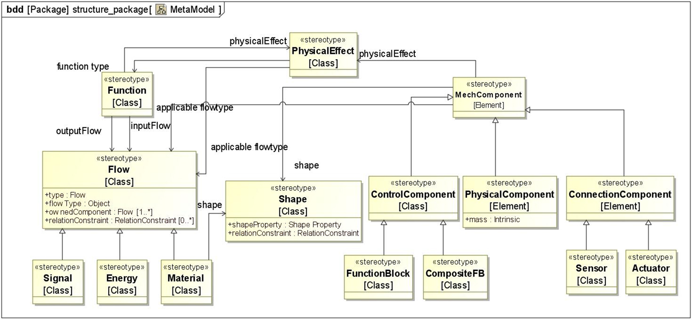
The metamodel is the core abstract class that is imperative for architecture modeling. The entire architecture of a system can be represented by the metamodel. They can be instantiated in many different ways according to the requirements of the system architecture design. The metamodel of ArchME is shown in Figure 2. Here, behavior is not an independent element; it relies on the component. Function is represented by flow. The component is divided into three types. In addition, the function and component are related to each other through the physical effect or flow.
Metamodel of ArchME.

4. ELEMENTS OF ArchME
Based on the discussion above, ArchME should involve four types of elements, that is, structure related, function related, behavior related, and connection related, which are detailed as follows.
4.1. Structure-related element
Structure-related elements are used to model the basic components of physical system architecture. The challenge is modeling components in different domains consistently. Structure-related elements are divided into two parts: elements to support dynamic simulation and elements to support detail design. The former refers to behavior-related information while the latter refers to geometry-related information.
4.1.1. Elements to support dynamic simulation
As mentioned previously, the mechatronic system is made up of a physical subsystem, control subsystem, sensors, and actuators. Although the physical components may belong to different domains, they are similar in behavioral aspects because they all follow energy conservation laws and material conservation laws.
Therefore, the components of the physical system, such as mass and spring, can be represented uniformly based on dynamic law at the system level. Generally, the following three attributes (intrinsic attribute, through variable, and across variable) should be considered:
-
1. Intrinsic attribute: This is the attribute whose value is constant for a specific component. It reflects the basic property of a physical component. During the process of system design, it should be set and adjusted if necessary.
-
2. Through variable and across variable: These are state variables of the physical component; their values are used to reflect the current state of the physical system. Note that each physical domain has its own specific through variable and across variable. The definition of the through and across variables of a specific component should be consistent with its present physical domain. For example, when a physical component is following translational motion, its through variable is force and its across variable is velocity. However, when it is following rotational motion, its through variable is torque and its across variable is rotational speed.
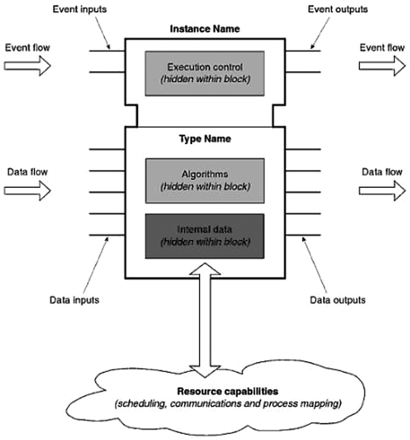
The components of the control subsystem are totally different from those of the physical subsystem because the signal flow is the main input and output of control components. The energy conservation law and the material conservation law are not suitable for control components. The International Electrotechnical Commission (IEC) proposed a new standard for representing the control components, that is, the IEC61499 standard based on IEC61131 (Lewis, Reference Lewis2001). The core part of this standard is the function block. The purpose of the standard is to make the design and implementation of the control subsystem separate. Therefore, designers can focus on system function design to improve the modularity and reusability of the system function and ignore subsequent deployment. This standard is becoming the basis of a new-generation control system design. In this study, the modeling of the control system is based on the IEC61499 function block.
It can be seen from Figure 3 (Lewis, Reference Lewis2001) that function block describes the software function unit of the control system in an object-oriented way. There are two kinds of function block: the basic function block and the composite function block. The latter is composed of the former. The basic attributes of the function block are event input/output, data input/output, and internal data. Different function blocks are connected through ports to fulfill certain functions. The port used to transmit an event is named the “event port.” Similarly, the port used to transmit data is named the “data port.” There is a relationship “with” between data port and event port, which means that the corresponding data port is refreshed according to a signal when an event occurs.
Illustration of IEC61499 function block (Lewis, Reference Lewis2001).

The behavior of the function block is described by the execution control chart (ECC) and a series of control algorithms. The ECC is the core of a function block and acts as the behavior organizer. Actually, it is a finite state machine that contains the EC state, EC transition, and EC action. Each EC state may be connected with many EC actions, which means that a specific algorithm is executed under this state and the corresponding output event is generated when the algorithm ends. EC transition is triggered by a specific Boolean condition or event.
4.1.2. Elements to support detail design
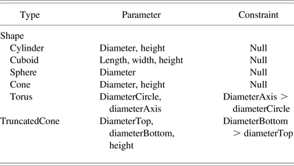
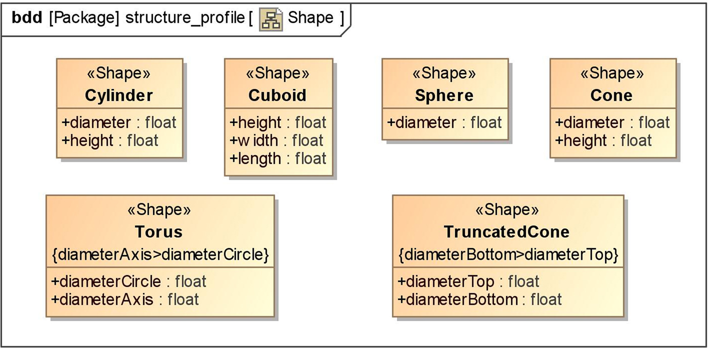
In the early stages of system design, although accurate geometric information is not necessary, architects need to know the approximate geometric information of components to design system layout. In this stage, the components’ shape can be approximated by the basic geometric shape (Komoto et al., Reference Komoto and Tomiyama2012). The rough geometric information may help the designers of the detail design stage greatly. In this study, six basic shapes are used as shown in Table 1: cylinder, cuboid, sphere, cone, torus, and truncated cone. Each shape has corresponding size parameters. In addition, some shapes should satisfy specific constraints. It should be noted that the six basic shapes may not be enough. New basic shapes can be defined if necessary.
Basic shape definition

The structure of a complex system can be defined by using basic components combined together through ports following certain geometry constraints. Therefore, the basic geometry constraints and ports should be defined. According to Chen (Reference Chen2008; Chen et al., Reference Chen, Bankston, Panchal, Schaefer, Wang and Nee2009), the relationship between basic elements such as the point, line, and plane are used to define the geometric constraints. In this way, the relative space relationship is defined, and the initial layout of the mechatronic system is generated. According to Chen (Reference Chen2008; Chen et al., Reference Chen, Bankston, Panchal, Schaefer, Wang and Nee2009), there are two kinds of space constraints in the computer-aided design (CAD) system: the point constraint and direction constraint. The former indicates the point coincidence, whereas the latter includes parallelism, verticality, and so on. The entire initial spatial layout is determined by the modeling of components’ shape and constraint.
4.2. Function-related elements
In functional basis, function and flow are classified and described. However, they lack clear semantic descriptions, and thus cannot be used directly during architecture modeling. Here, a study is conducted to clearly represent the physical property and shape property based on functional basis.
4.2.1. The modeling elements of the physical property of function flow
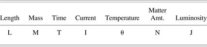
For a flow property, both property type and property value are considered. Generally, a flow may contain many properties belonging to different domains, and even the same property may contain different types of units. To conveniently identify the physical association between different properties, seven basic physical dimensions, as stated in Object Management Group systems modeling language, are introduced in Table 2 to add physical semantics to the value type. Each dimension of physical property can be derived from the seven basic dimensions except the dimensionless quantity. For example, the dimension of velocity is LT−1, and that of force is MLT−2. The introduction of dimension to the model flow property can support dimension analysis in the modeling of system architecture and then provide a foundation for reasoning in the system architecture model.
Basic physical dimensions

The relation constraints for the output elements of the Tetra Pak

In addition to single flow, there is composite flow. To support modeling of composite flow, OwnedComponent and OwnedRelation are defined in our previous work (Yuan & Liu, Reference Yuan and Liu2014). The former is used to represent the constituents of composite flow, whereas the latter is used to represent the relationships between these constituents. Take a stapler as an example; the input flows are the page and cover, the output flow is the book. At a high level, the output is only an object. However, the book has two OwnedComponents: the page and cover. Moreover, the OwnedRelation is used to describe the “link” relationship between the page and cover. Nagel et al. (Reference Nagel, Bohm, Stone and McAdams2007) noted that the “carry” relationship between the primer flow and carrier flow should be identified. Sen et al. (Reference Sen, Summers and Mocko2013) added constraints to the carry relationship logically. Generally, the material flow can carry energy flow, signal flow, and other material flow. The energy flow can carry signal flow. The material flow carrying other material flow can be implemented by the flow type mixture directly. However, the mixture relationship cannot describe the necessary semantics of solid-solid composite flows. Therefore, solid flow must be studied further, as described in the next subsection.
4.2.2. The modeling element of the shape property of solid flow
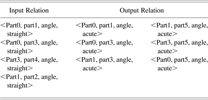
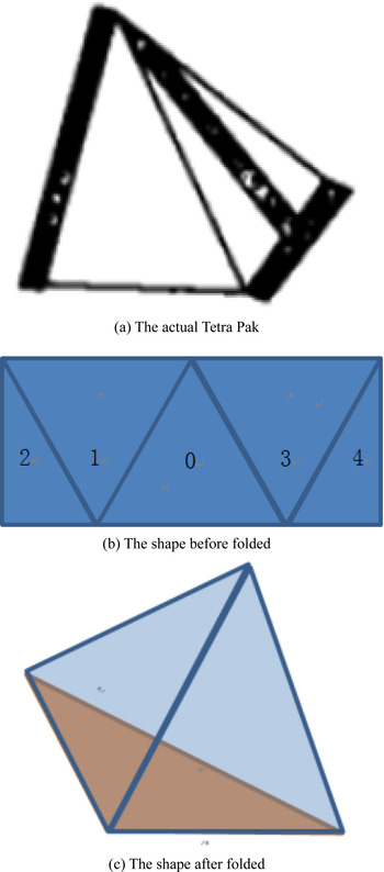
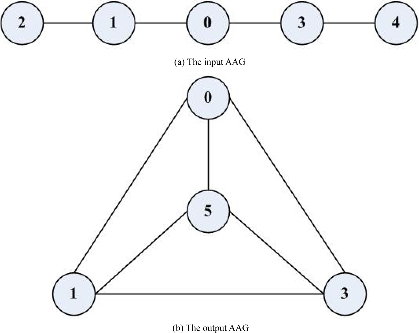
For solid material flow, shape property is an important semantic. Regular shapes can be described by basic shapes in Table 1. Irregular shapes can be represented as a combination of these basic shapes. To support function modeling and function reasoning, an adjacent attribute graph (AAG)-based method is proposed for complicated shape representation (Yuan et al., Reference Yuan, Zhang and Liu2015). In this method, the composite material shape is described by simple element shapes and the relation constraints between them. Take the Tetra Pak shown in Figure 4a as an example; the paperboard before being folded is flat with an imprint, as shown in Figure 4b. The flat paperboard becomes a tetrahedron after being folded, as shown in Figure 4c. Based on the proposed AAG method, the AAGs of the Tetra Pak's input and output are shown in Figure 5. The input paperboard is composed of five simple shape elements, which are all plane elements. As the five single elements are coplanar, the angle relationships between them are flat as shown in Figure 5a. The relationship between the output elements are shown in Figure 5b. Their specific relation constraints are shown in Table 3. It can be seen from the example that the AAG-based modeling method can clearly express the semantics of complex material flows.
The Tetra Pak and its shapes before and after being folded. (a) The actual Tetra Pak, (b) the shape before folded, and (c) the shape after folded.

The adjacent attribute graphs (AAGs) of input and output complex solid flows. (a) The input AAG and (b) the output AAG.

4.3. Behavior-related elements
Behavior modeling is important for complex mechatronic systems. It can be used to express the user requirements of system behavior. In addition, it can be used to support system-level simulation to verify the correctness of the designed architecture model. However, behavior modeling is difficult; its complexity is derived from two aspects:
-
1. Hybrid behavior modeling: A complex mechatronic system may contain three types of behavior. It is necessary to model them in a unified way.
-
2. Multidomain integration: Different domains may have different characteristics and influence each other.
Moreover, the two aspects are coupled with each other.
In this study, a state machine-based hybrid behavior modeling method (Cao et al., Reference Cao, Liu and Paredis2011) is used. It contains a series of states and transitions to indicate event-based discrete behavior. Each state has its activity, which indicates the continuous change in each state. In this method, the state machine is formalized based on discrete behavior, and then continuous behavior represented in the function is added to each state. In this way, the continuous behavior and discrete behavior are combined together, and thus hybrid behavior is modeled. Specifically, continuous behavior is represented by the differential algebraic equation, whereas discrete behavior is represented by the transitions between states. The core elements of discrete behavior are the state and transition. Here, the state is used to describe the condition of the mechatronic system. In each state, the system runs according to the same rule. The states are connected with each other by transitions, which are triggered by defined semantic rules.
4.4. Connection elements
Function, behavior, and structure are three separate parts of the system architecture. To model them together as a whole, connection elements are needed. Here, two kinds of connection elements are defined: the connection element used to connect elements in the same part and that used to connect elements in different parts.
4.4.1. Connection element used to connect elements in the same part
It is obvious that different parts may have different features, and thus they cannot be connected in the same way. There are mainly two types of connection elements to connect elements in the same part: the flow and the parametric model.
The flow is chosen as the connection element in the function part. As stated in Yuan and Liu (Reference Yuan and Liu2014), the changes of a flow can be divided into three types: property change of a single flow, type change of a single flow, and relation change between different flows. For structure and behavior, the parametric model is used to connect the related parameters. It is used to build a specific network of constraints according to mathematical equations such as {F = m × a}. It supports specific engineering analysis, such as performance analysis, and cost analysis. The elements that need to be modeled are the constraint, such as {F = m × a}, and the parameters of the constraint, such as F, m, and a.
4.4.2. Connection element used to connect elements in different parts
In the architecture model, structure, function, and behavior are influenced by each other. The changes of function will lead to changes of structure. The changes of structure may also cause the changes of behavior and function. Therefore, the constituents of the architecture model should be related to each other. To establish the connection mechanism, the connection elements for elements in different parts should be defined. Here, flow and physical effect are chosen as the connection elements, which will be detailed in Section 5.6.
As mentioned previously, SysML is a general purpose modeling language; it needs to be extended in order to support modeling for specific applications of a specific system. To support the architecture modeling of a mechatronic system, the semantics of the above four aspects (structure, function, behavior, and connection) must be added to SysML. In ArchME, the function element is used to model the logical system architecture, which considers the physical and shape property of flow (both are used to support function analysis and reasoning); the structure element is used to model the physical system architecture, which considers the physical and geometric property of the component (the former is used to support dynamic simulation, and the latter is used to support detail design); the behavior element is used to support the behavior modeling of components; and the connection element is used to connect the elements in the same part and between parts (the former is used to model the constraints and relationship between properties in an element, and the latter can support automated design).
5. DETAIL OF ArchME
Based on the above analysis of modeling elements, a SysML extension for mechatronic system architecture modeling named ArchME is proposed. First, a brief introduction to the SysML diagram is given.
5.1. A brief introduction to the SysML diagram
There are nine diagrams defined in SysML, and they can be divided into three categories. Of these, block definition diagram, internal block diagram, and parametric diagram are frequently used in this study. Block definition diagram defines the blocks and its properties; internal block diagram describes the relationships of internal subblocks; parametric diagram describes the parameter constraints that should be satisfied by block attributes.
5.2. The structure of ArchME
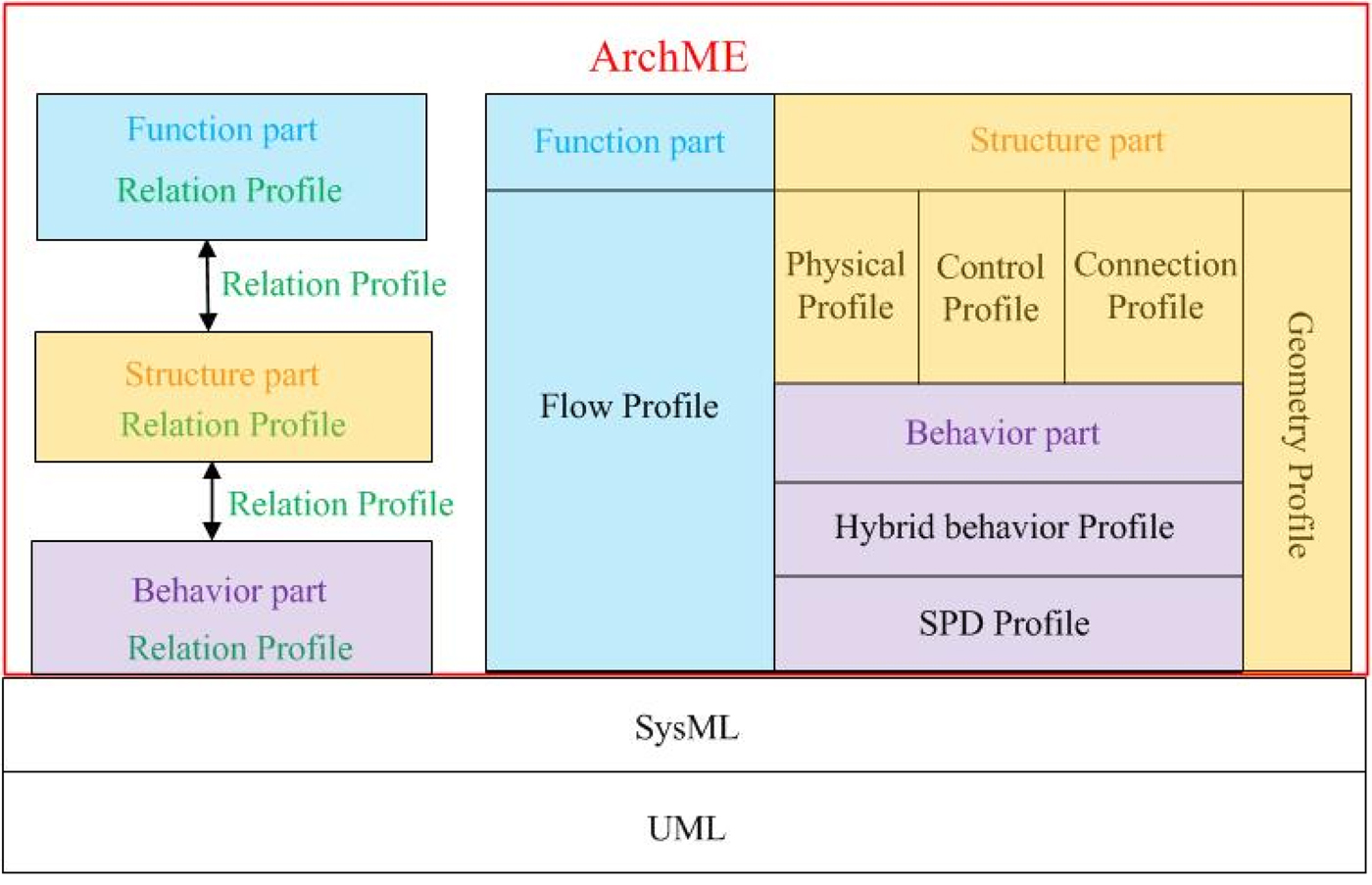
As shown in Figure 6, there are eight profiles in ArchME, which can be divided into three large parts and one relation profile. The different parts and relation profiles are shown in different colors. The function is modeled in the flow profile. The behavior of the structure is modeled using the physical, control, and connection profile, while the geometry of the structure is modeled using the geometry profile. The behavior of the structure is modeled based on the sequenced parametric diagram (SPD) profile and the hybrid behavior profile, which is included in the behavior part. The entire ArchME is divided into the left part and the right part to illustrate the relationship between the relation profile and the three basic parts. It is obvious that the relation profile is used to integrate different parts and different elements in the same part. The SPD profile, hybrid behavior profile, physical profile, control profile, and connection profile have been introduced in Cao et al. (Reference Cao, Liu, Fan and Fan2013) as components of a modeling language named UBML. In this study, they are extended to satisfy new needs such as design automation, detail design, and system verification in addition to dynamic simulation.
The structure of ArchME.

5.3. The structure part
Here, structure indicates the composition of components and how they are related to each other to achieve needed behaviors. There are three types of components: physical components, control components, and connection components (e.g., sensor, actuator). Different types of components have different behavior attributes to model, so three corresponding profiles are applied: the physical profile, control profile, and connection profile. Details of these profiles are defined in Cao et al. (Reference Cao, Liu, Fan and Fan2013). Each component has geometric attributes. To support subsequent detail design, rough geometric information is defined in the geometry profile (detailed in Appendix A). In addition, elements in the physical profile are connected through the relation profile, which is outlined in detail in Section 5.6, and the same is the case for elements in control profile, connection profile, and geometry profile.
5.4. The function part
To support automated design, function is represented in a formalized way. As elaborated in Section 4.2, function is abstracted as changes of flow, so the flow profile (detailed in Appendix B) is defined.
5.5. The behavior part
There are some studies on the hybrid behavior of the mechatronic system. Based on hybrid automata (Ho & Nicollin, Reference Ho and Nicollin1995), CHARON (Alur et al., Reference Alur, Dang, Esposito, Hur, Ivancic, Kumar, Lee, Mishra, Pappas and Sokolsky2003), form a hierarchical, modular model. The representation unit of behavior in CHARON is the mode that is divided into the composite mode and the atomic mode. The composite mode is composed of the atomic mode. Discrete conversion occurs between different modes, whereas continuous behavior is described in the atomic mode with the use of equations. However, CHARON is a textual modeling language without standard visual representation. HybridUML (Berkenkötter et al., Reference Berkenkötter, Bisanz, Hannemann and Peleska2006) is a UML2.0 profile based on CHARON. HybridUML takes a subset of UML, modifies it according to CHARON, and gives it precise semantics. However, because there is no continuous behavior modeling elements in UML, the continuous behavior in HybridUML is also modeled at the text level.
To model discrete behavior and continuous behavior consistently, two basic profiles (the SPD profile and the hybrid behavior profile) of mechatronic system behavior (defined in Cao et al., Reference Cao, Liu, Fan and Fan2013.) are applied in the behavior part. The physical profile, control profile ,and connection profile applied in the structure part are based on these basic profiles.
5.6. Relation profile
The relation profile is special because it is not included in the above three parts. Corresponding to the classification detailed in Section 4.4, the relation profile can be divided into two parts.
5.6.1. Models used to link elements in the same part
As mentioned previously, function can be abstracted as transformation between flows. The tuple <inputFlow, outputFlow> should be defined. Here, the number of inputFlow and outputFlow may be one or more. In this way, each function can be represented in a tuple including input flows and output flows. Different functions can be connected through flows.
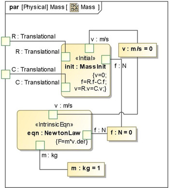
Similarly, elements are all represented through property parameters in behavior part and structure part. These parameters are connected together following specific constraints. Constraints are represented in equations. As shown in Figure 7, intrinsic equations and initial conditions of mass block are bound with its corresponding property parameters, so these parameters change according to specific rules. In this way, the behavior of a mass block is described.
The parametric diagram of a mass block.

5.6.2. Models used to link elements between different parts
To support automated design, elements that link different parts should be formalized. In our opinion, flow and physical effect can be regarded as connection elements. When the input flows and output flows of a component correspond to the input flows and output flows of a function, the component can be considered as a candidate to fulfill this function. The real match process may be more complex. For example, the input flows and output flows may not match completely. In this case, the physical effect can be used as a supplement for matching. It can be described by physical laws and its formula (Pahl & Beitz, Reference Pahl and Beitz2007). If a component can provide a physical effect that is just needed by a function, they can match with each other; that is to say, the function can be accomplished by the component. Similarly, there may be the problem of not matching completely. For example, a component may provide more than one physical effect, and it may provide some physical effects that contradict with the function. In this case, only the main physical effect is considered in this stage, and some evaluation mechanisms are used to select the optimal component. It does not matter whether flow is first considered or physical effect is first considered.
6. IMPLEMENTATION AND CASE STUDY
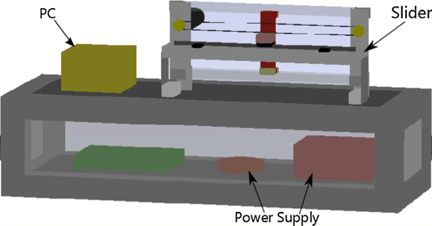
In this study, MagicDraw is used, which supports the modeling of UML/SysML. The mechatronic system shown in Figure 8, where the simplified ink-jet printer (Ni & Broenink, Reference Ni and Broenink2014) is used to verify the effectiveness of ArchME. The physical component “slider” moves back and forth under the control of an embedded computer.
A simplified ink-jet printer (Ni & Broenink, Reference Ni and Broenink2014).

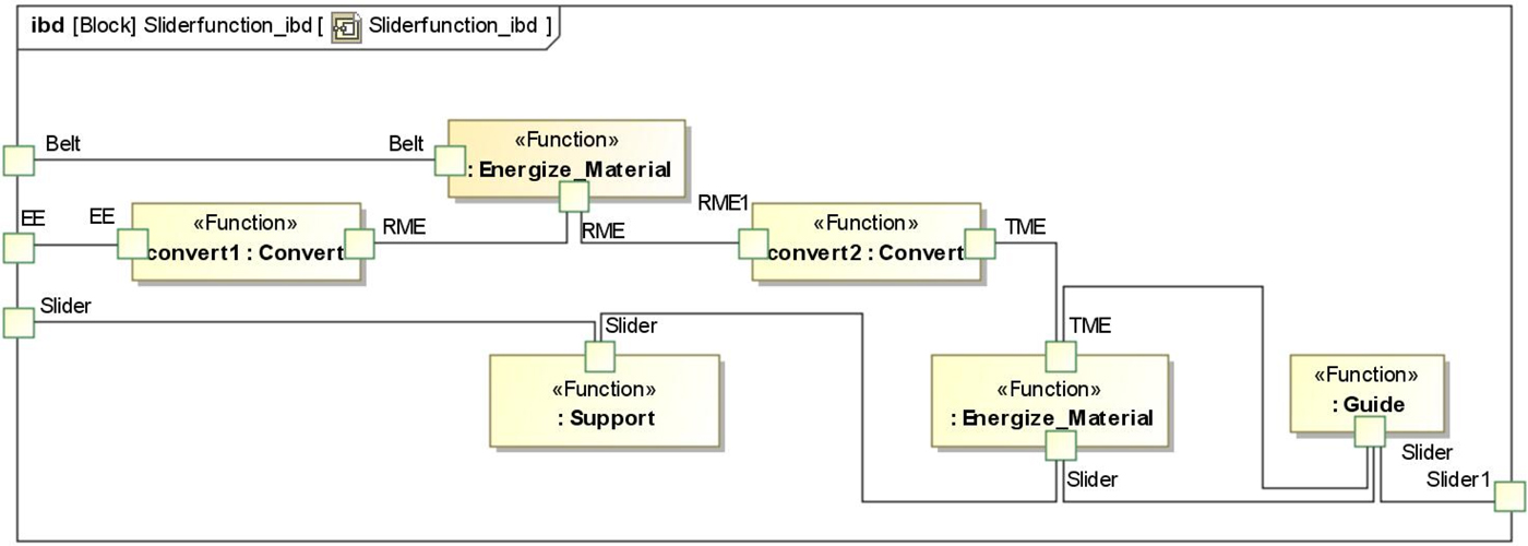
The function structure is studied from the perspective of flow; only the main flows are considered here. The example's general function is to convert electrical energy to translational energy. Using the proposed ArchME, subfunctions obtained from function decomposition are modeled as shown in Figure 9. If a component has an input flow whose type is “Electrical Energy” and an output flow whose type is “Rotational Mechanical Energy,” it can be chosen to realize the “Covert1” function. It is similar to function “Convert2.” As for the subfunction that has no obvious flow change, for example, function “support,” the physical effect can be used for matching between the function and component. In this way, several options of physical system architecture can be automatically derived from the logical system architecture shown in Figure 9.
The function model of the simplified ink-jet printer.

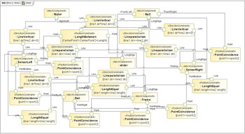
In the physical system architecture, several components are grouped together in a certain spatial relationship. As shown in Figure 10, the ink-jet printer system contains two sensors, one motor, one belt, one slider, one rail, and one frame (because the controller and actuator are embedded in the computers, they are not considered here). The shape of each component and the spatial constraints between these components are modeled by the geometric elements defined in the geometry profile. The rough spatial relationship between components can be seen with this figure. This geometry model can also be converted to CAD software (Fan et al., Reference Fan, Liu, Liu and Ye2015) to show the rough shape of the component and the spatial constraints between components. This model can be used to guide detail design.
The rough geometry information model of the simplified ink-jet printer.

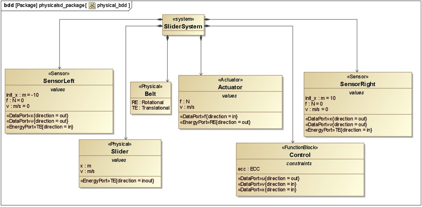
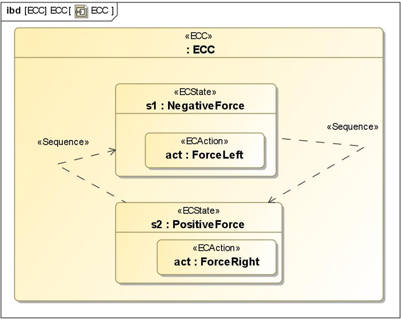
From the perspective of behavior, the system contains two sensors, one belt, one slider, one controller, and one actuator (the frame and rail that are not involved in hybrid behavior are ignored here). Each component has its own constitutive equation and value properties as shown in Figure 11. To realize the hybrid behavior, the specific control behavior is given by a controller as shown in Figure 12. There are two states: NegativeForce and PositiveForce. There is continuous behavior in each state. In the NegativeForce state, a left-directed force is given, whereas a right-directed force is given in the PositiveForce state.
The components of the simplified ink-jet printer.

The control behavior model of the simplified ink-jet printer.

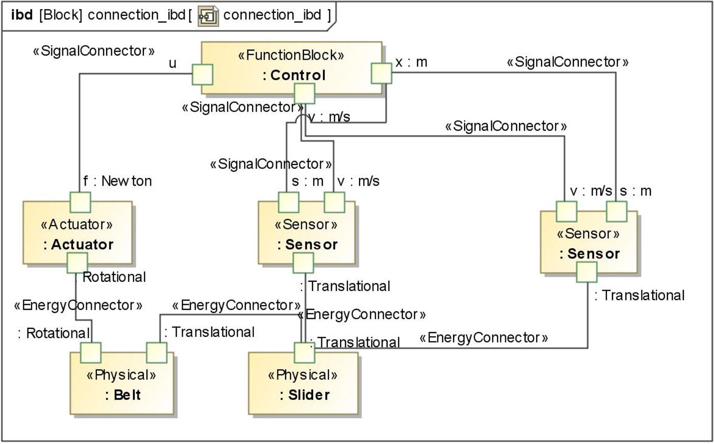
As shown in Figure 13, the components are connected through ports. The energy ports are connected through EnergyConnector, which follows the general Kirchhoff's law. Signal ports are connected through SignalConnector, whose values are transmitted as signals. By modeling hybrid behavior, dynamic simulation can be supported (Cao et al., Reference Cao, Liu, Fan and Fan2013).
The connection model based on an internal block diagram.

It can be seen from the above case study of the ink-jet printer that ArchME can be used to support automated system design, dynamic simulation, and detail design.
7. CONCLUSION
The architecture model is central to the entire system. It can be seen as the results of architecture design and the start of subsequent detail design. Although several modeling languages such as AADL, ExSAM, and UBML are proposed, they still do not support the entire process of mechatronic system architecture modeling. In this study, a SysML extension, ArchME, is proposed for the architecture modeling of complex mechatronic systems. The main contributions are as follows:
-
1. The requirement for the architecture design of mechatronic systems is analyzed from the system aspect. A series of profiles are defined in a consistent way to support modeling in different parts (function, behavior, structure). In this way, system designers can communicate easily using ArchME.
-
2. The modeling elements for a mechatronic system are defined explicitly. In particular, geometry-related and behavior-related modeling elements are both defined in ArchME, which can be used to support simulation analysis and detail design separately.
-
3. Architecture models from function to structure are related together formally and consistently. Therefore, design changes can be easily traced, and the system design process can be automated.
However, this study is still in its infancy. First, there is no rigorous grammar in ArchME, which is necessary for automated reasoning and consistency verification. Second, in the relation profile, it is easy to match function and corresponding component by comparing their physical effect or flow. However, the difficulty is finding the most suitable component to fulfill the function and connecting them using less space, and so on. Third, only modular architecture (Ulrich, Reference Ulrich1995) is considered in this study. The integral architecture (Ulrich, Reference Ulrich1995), which is another common architecture in design, should also be considered in future work. These deficiencies will be addressed in future research.
ACKNOWLEDGMENTS
The authors appreciate the support from the National Key Technology Support Program (2016YFD0400301), the National Science Foundation of China (61572427, 61672247), and the Key Project of Science and Technology of Zhejiang Province (2014C01052, 2014C01017).
Ruirui Chen is currently a PhD candidate in the State Key Lab of CAD&CG at Zhejiang University. Her main research interests are model-based systems engineering and system design.
Yusheng Liu is Professor in the State Key Lab of CAD&CG at Zhejiang University. He received his PhD in mechanical engineering from Zhejiang University and continued his postdoctoral research at the State Key Lab of CAD&CG at Zhejiang University and the City University of Hong Kong. He was a Visiting Scholar at the Georgia Institute of Technology. His main research interests are model-based systems engineering, computer-aided tolerancing and inspection, and content-based three-dimensional model retrieval.
Yue Cao is a PhD candidate in the State Key Lab of CAD&CG at Zhejiang University. Her main research interests are model-based systems engineering and system design.
Jianjun Zhao is an Associate Professor in the School of Mechanical Science & Engineering at Huazhong University of Science and Technology, where he received his PhD in mechanical engineering. Dr. Zhao's main research interests are uniform multidomain simulation, model-based systems engineering, and the integration of CAD/computer-aided manufacturing.
Lin Yuan is a PhD candidate in State Key Lab of CAD&CG at Zhejiang University. His main research interests are model-based systems engineering and system design.
Hongri Fan is a Lecturer in the College of Mechanical Engineering at Shanghai University of Engineering Science. He received a PhD in computer science from Zhejiang University. Dr. Fan's research interests include model-based systems engineering, SysML, and collaborative design.
APPENDIX A GEOMETRY PROFILE
To support subsequent detail design, a geometry profile containing approximate shape and spatial relation constraint information should be defined. Baysal et al. (Reference Baysal, Roy, Sudarsan, Sriram and Lyons2005) propose a method to model the geometry and position on UML, but the general position for each part is difficult to calculate using this method. Fan et al. (Reference Fan, Liu, Liu and Ye2015) studied geometry modeling of mechatronic systems in the early design stage by extending SysML. It has been used here because it is convincing and easy to understand. Therefore, “Shape” inherited from “Block” is proposed. As shown in Figure A.1, six basic shapes are defined: cylinder, sphere, cuboid, cone, truncated cone, and torus. For each shape, both the parameters and the constraints between them are defined. For example, the bottom diameter of a truncated cone should be greater than that of the top one.
Six basic geometric shapes.

Connection interfaces between basic shapes should also be defined to represent complex shapes and the spatial relation between different components. According to Chen (Reference Chen2008; Chen et al., Reference Chen, Bankston, Panchal, Schaefer, Wang and Nee2009), the constraint objects of space geometry can be divided into three types: point, line, and plane. Correspondingly, a component can have three types of interface. Here, BasicInterfaceFeat is used to define the interface property. As shown in Figure A.2, “point” contains the coordinate definition, “line” contains direction information, and “plane” contains normal and center point information, Moreover, two basic types of plane are further defined to support modeling flexibility: RectangularPlane and RoundPlane. Based on the definition of basic constraint objects, constraint relations such as fixed can be defined directly.
The basicInterfaceFeat.

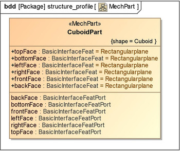
Based on the above analysis, the geometric information of the component is defined, which contains the shape information and interface features. Based on the shape information, different types of interfaces are defined. The spatial constraints are determined by defining the relationships of corresponding interfaces. Here, MechPart is defined to represent the mechatronic component. As shown in Figure A.3, a component named CuboidPart is represented with our mechanism. According to its shape, basic attributes and ports are defined, and each attribute and each port have their own stereotypes defined in this paper.
A component instance.

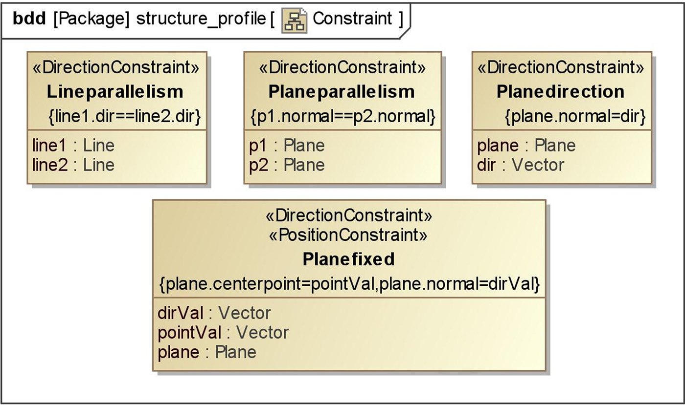
According to Chen (Reference Chen2008; Chen et al., Reference Chen, Bankston, Panchal, Schaefer, Wang and Nee2009), there are two types of spatial constraint relationships in the CAD system: point constraint and direction constraint. Correspondingly, two stereotypes are defined as follows: PositionConstraint and DirectionConstraint. Some instances of spatial constraints are given in Figure A.4. Here, LineParallelism and PlaneParallelism represent the parallelism relationship between two lines and two planes, respectively. Point coordinates and direction information can be constrained at the same time to represent Planefixed. Planedirection is used to fix the direction of a plane.
The instances of some constraints.

APPENDIX B FLOW PROFILE
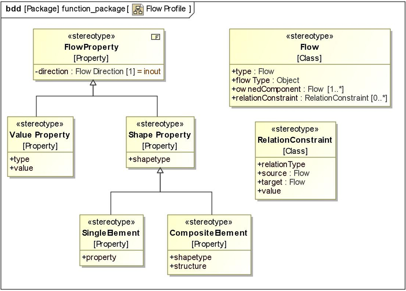
As shown in Figure B.1, the flow profile contains three main elements: flow type based on functional basis, flow property based on physical dimension, and shape modeling method of solid material based on AAG. According to functional basis, the flow type can be material, signal, energy, and their subtypes. For a value property, both property type and property value are considered. Here, the type is defined based on the physical dimensions mentioned previously. The shape property of a solid material can also be represented by using basic shapes defined in the geometry profile. In the flow profile, two stereotypes about flow property are defined: Value Property is used to represent regular properties and Shape Property is aimed mainly at solid material. Moreover, RelationConstraint is used to define relation constraints between basic elements in the composite flow, and Flow is used to represent flows in function.
Flow profile.