I. INTRODUCTION
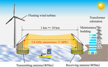
Expanded use of renewable energy is urgently required as an alternative to fossil fuels or nuclear power to develop a sustainable society. SSPS (Space Solar Power System) is proposed as a large-scale renewable power plant in space and is studied for the last 40 years [Reference Glaser1–Reference Matsumoto3]. Microwave power transmission technology was studied and developed as a method of transmitting electrical energy from space to earth [Reference Shinohara4–Reference Brown8]. Currently, other applications of microwave power transmission, including battery-less sensor systems [Reference Yoshida, Hasegawa and Kawasaki9] and wireless charging of electric vehicles [Reference Ishikawa and Shinohara10] were also examined. Furthermore, the ocean is known as another frontier of renewable energy. Recently, a terrestrial microwave power transmission system was proposed as an effective method to collect and carry solar and wind energy from sea to land [Reference Ishikawa11]. Figure 1 shows a schematic illustration of a terrestrial microwave power transmission system. In this system, microwave power can be transmitted for an approximate distance of 10 km with a 50 m diameter antenna at a frequency of 5.8 GHz. It is assumed that the total power of a microwave beam corresponds to approximately 1 MW. In contrast to overhead power lines and submarine cables, microwave power transmission does not cause significant disturbances in the fishing industry, dredging work, and marine traffic.
Terrestrial microwave power transmission for collecting ocean energy.

In microwave power transmission involving high power, it is important to sufficiently suppress energy leakage outside the system to ensure human safety and avoid interference with other wireless systems. Extant research has proposed and investigated an effective design method for a low-leakage microwave beam using synthetic electromagnetic field of spherical wave [Reference Matsumuro, Ishikawa, Ishikawa and Shinohara12]. It was shown that a low-leakage beam could be realized by inputting a complex amplitude distribution of the cross-section to the discrete array antenna. In practical conditions of terrestrial microwave power transmission, it is necessary for the retrodirective system to realize beam control toward the target receiving antennas. Fluctuations of the atmospheric refractive index and the vibration of the antennas by the ocean wind are required to consider. With respect to the retrodirective system of terrestrial microwave power transmission, it is necessary to use the same frequency for the pilot signal as that of microwave power to avoid frequency dependence of the atmospheric refractive index. Multipath propagation due to the ground or sea surface also poses challenges. Thus, this study involved advancing a fundamental single-frequency retrodirective system for terrestrial microwave power transmission. The proposed system has two advantage features. The first feature included a pilot signal that radiated from the entire surface of the power-receiving antenna in a beam formation. It was possible to avoid the influence of the ground or the sea surface by sharing the transmission path of the pilot signal and the microwave power. The second feature of this system was that vertical and horizontal polarizations were applied to the pilot signal and microwave power, respectively. It was possible to avoid the frequency dependence of the refractive index of the transmission path by using the same frequency for the pilot signal and the microwave power.
It is widely known that a retrodirective system is an effective technology of phased array antenna to transmit microwaves back in the arriving direction using a reciprocal theorem [Reference Pon13, Reference Sharp and Diab14]. However, the isolation of the pilot signal and microwave power is a problem in terms of practical design. An unrealistic isolation level is required for the circulator due to the difference in the power level when the same antenna elements are used for the pilot signal and microwave power. Recent studies on a retrodirective system for wireless power transmission [Reference Fairouz and Saed15–Reference Hsieh19] indicate that two different frequencies are typically used for the pilot signal and microwave power to avoid the isolation problem. Thus, it is necessary to arrange the antennas of the pilot signal and microwave power in different spaces to avoid mechanical interference. A small part of the microwave power antenna is replaced by that of the pilot signal in the case of a planar array antenna. As a result, degradation of reciprocity characteristics due to multipath propagation of the spread pilot signal and frequency dependency of the atmospheric refractive index are inevitable in terrestrial microwave power transmission.
Recently, a retrodirective system with the approximately single frequency using dual-mode antenna elements was proposed and high-performance phase conjugator was developed [Reference Fusco and Buchanan20, Reference Fusco and Buchanan21]. However, further improvement in the isolation of the antennas is required. Thus, a dual-mode dielectric resonator antenna was developed to solve the fundamental isolation problem of the pilot signal and microwave power in a single-frequency retrodirective system. It is also possible to emit the beam pilot signal from the entire surface of the power-receiving antenna since all the antenna elements deal with both the pilot signal and microwave power. The high-isolation level for the pilot signal and the microwave power is ensured by a cross-shaped hemispherical dielectric resonator structure. Various antennas with multiple frequencies and polarizations were studied in the research field of wireless communication [Reference Liu, Guo and Huang22–Reference Luk and Leung26]. However, few studies focused on the high-polarization isolation level as planer array antenna elements for a retrodirective system of microwave power transmission.
In this study, the feasibility and effectiveness of a single-frequency retrodirective system with a beam pilot signal for terrestrial microwave power transmission were basically studied. In Section I, the configuration of the system is elaborated and the expected effect is described. In Section III, the operation of the single-frequency retrodirective system with a beam pilot signal is simulated by a beam propagation method (BPM). In Section IV, a dual-mode dielectric resonator antenna element for sharing the beam pilot signal and microwave power is discussed.
II. CONFIGURATION OF A SINGLE-FREQUENCY RETRODIRECTIVE SYSTEM WITH A BEAM PILOT SIGNAL
In this section, the configuration of a single-frequency retrodirective system with a beam pilot signal is discussed in detail.
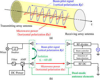
Figure 2 shows the schematic illustration of a configuration of the proposed retrodirective system. In the terrestrial microwave power transmission, there was a possibility that the refractive index of the transmission path could change according to the frequency as well as the weather and the altitude. The transmission distance of 10 km was equivalent to approximately 200 000 wavelengths of the microwave at a frequency of 5.8 GHz. The permissible value of the refractive index due to the change in the frequency was expected to be extremely small. In the single-frequency retrodirective system, precise reciprocity was expected under such a severe environment. It was difficult to ensure separation of the pilot signal and microwave power when the same frequency was used for the pilot signal and microwave power because signal-processing devices in the frequency domain cannot be used. In order to solve this problem, vertical and horizontal polarizations were applied for the pilot signal and microwave power, respectively. As shown in Fig. 2(a), a pilot signal with vertical polarization (denoted as E y ) is first radiated from the power-receiving antenna. Following this, microwave power with horizontal polarization (denoted as E x ) is radiated to the power-receiving antenna by conjugating the phase and amplifying amplitude of the pilot signal in the power-transmitting antenna. Additionally, in this retrodirective system, the pilot signal is transmitted from the entire surface of the power-receiving antenna to avoid the influence of multipath by ground or sea surface. It is possible to emit a non-spread beam by using a sufficiently large area for the wavelength. The influence of multipath can be eliminated because the energy does not reach by ground or sea surface. Given that the beam pilot signal is not affected by multipath propagation, polarization should be maintained assuming that the refractive index of the atmospheric transmission path has no anisotropy.
Schematic illustration of a retrodirective system with a beam pilot signal.

A degenerated dual-mode antenna element with high-level isolation as shown in Fig. 2(b) is important to realize this system. A side lobe or grating lobe due to the large pitch between each antenna elements is likely to occur if separate antenna elements are used for the pilot signal and microwave power. Degenerated dual-mode antenna elements are arranged in both the power-transmitting antenna and the power-receiving antenna. In the power-transmitting circuit, a conjugated phase of the pilot signal was produced by using such as a mixer and frequency doubler. The microwave is amplified by DC power for the power transmission. The isolation level of polarization of dual-mode antenna elements is required to exceed 60 dB assuming a system gain of the power-transmitting antenna of 20 dB and a margin of 40 dB for the high-accuracy operation of the phase-conjugating circuit. In this system, the power of the beam pilot signal is determined by the system gain of the power-transmitting antenna. The total power of the beam pilot signal corresponds to 10 kW assuming microwave power of 1 MW and a system gain of 20 dB.
It is possible to simplify the circuit configuration of the power-transmitting antenna by using the same frequency for the beam pilot signal and microwave power. Thus, high-power beam control equipment is not required. The power-transmitting antenna only generates the conjugate phase and the amplified amplitude of the beam pilot signal independently at each antenna element. The power-receiving antenna controls the power distribution and the beam direction of the microwave power by correcting low-power beam pilot signal. Improvement in total transmission efficiency is expected due to the installation of the phase shifter and the distributor in the power-receiving antenna in which the absolute value of the power is small. Moreover, in this type of retrodirective system, the pilot signal and microwave power propagate in almost the same transmission path in opposite directions. This system can be applied in a bi-directional power transmission system [Reference Popovic, Reveyrand, Schafer, Litchfield, Ramos and Korhummel27–Reference Ishikawa and Honjo29] by further development of the circuit configuration.
The configuration of a single-frequency retrodirective system with a beam pilot signal was discussed in this section. A pilot signal with the same frequency as that of microwave power was radiated from the entire surface of the power-receiving antenna to avoid multipath propagation and frequency dependence of the refractive index. As a result, the retrodirective system is expected to become simple, low-cost, and with high total efficiency. Thus, sufficient performance for the terrestrial microwave power transmission system will be obtained with this configuration.
III. EFFECT CONFIRMATION OF THE BEAM PILOT SIGNAL BY BPM SIMULATION
In this section, the propagation simulation of the beam pilot signal and the microwave power is simulated by the BPM.
In terrestrial microwave power transmission, it is necessary to assume the distributed refractive index as the perturbation from the designed value in the constant medium. The BPM is known as a powerful method to simulate the beam propagation without reflection in the case when the gradient of the dielectric constant of the medium in the cross-sectional direction is sufficiently small compared with the wavelength, such as that of an optical waveguide. It can be said that the BPM is suitable for the long-distance microwave power transmission because the refractive index distribution of the atmosphere is moderate as described in Section III(B). In the simulation of this section, it was assumed that the transmission distance was 10 km and that the diameter of transmitting and receiving antenna was 50 m each. The frequencies of the pilot signal and microwave power were 5.8 GHz (λ ≃ 5.17 cm) each. The time variation of the medium due to wind or temperature can be ignored because the propagation time for reciprocating the signal was approximately 5 ms. The microwave beam was simulated by a commercial simulation software OptiBPM using the FD-BPM algorithm [Reference Huang, Xu, Chu and Chaudhuri30]. The amplitude and phase distribution of the antenna input was determined by a methodology proposed in a previous study [Reference Matsumuro, Ishikawa, Ishikawa and Shinohara12] assuming that the electromagnetic field changed smoothly on the aperture of the antenna. Discretization effect of the array antenna elements was not included in this simulation. The grid length of the cross-section was set as 50 cm, and the step length of the propagation direction was set as 1 m.
By using the BPM simulator, it was first confirmed that the beam pilot signal could avoid multipath propagation. Next, it was shown that the propagation direction of the beam pilot signal was slowly bent by the gradient refractive index and that the transmission efficiency to the target degraded. The transmission path of microwave power was then simulated using the conjugate phase of the beam pilot signal, which constitutes a basic retrodirective method. It was shown that the microwave power accurately returned to the propagation path of the beam pilot signal in general. Finally, the correction of the radiation direction of the beam pilot signal to compensate the gradient refractive index was discussed. In the figures given in this section, the field distributions of the beam pilot signal and microwave power are displayed when the power-transmitting antenna is placed at 0 km and when the power-receiving antenna is placed at 10 km.
A) Multipath elimination by the beam pilot signal
The influence of multipath propagation can be avoided by using the beam pilot signal. This was confirmed via a simulation.
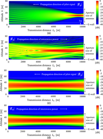
Figure 3 compares the electric field distributions of the spread pilot signal and the beam pilot signal. In this simulation, the electric wall was set at h = 0, which approximately represents the ground or the sea surface. The image method was used for the calculation of the boundary conditions of the electric wall since it was possible to set the boundary condition in the BPM. The altitude of the bottom edge of the antennas was set as 5 m. Interference fringes due to multipath emerged in the case of the conventional spread pilot signal from the small area of the power-receiving antenna as shown in Fig. 3(a). Figure 3(b) shows the electric field distribution of the microwave power by conjugating the phase of the pilot signal. The energy leakage occurred because the power and phase distribution of the transmitting antenna was disturbed by the interference fringes of the pilot signal. Conversely, the influence of the electric wall was eliminated in the case of the proposed beam pilot signal from the entire area of the power-receiving antenna as shown in Fig. 3(c). The beam pilot signal from the entire receiving antenna surface had high directivity compared with the spreading pilot signal from the small area of receiving antenna as shown in Fig. 3(a). Thus, the effect of multipath is eliminated because the energy did not reach the ground or sea surface represented by the electric wall. In this case, the transmission efficiency of the beam pilot signal exceeded 99%. Furthermore, conjugating the phase of the pilot signal resulted in a microwave power that almost corresponded to the distribution of the pilot signal as shown in Fig. 3(d). This result indicated that the terrestrial microwave power transmission with a beam pilot signal is available and effective.
Multipath elimination by a beam pilot signal. The electric wall sets at h = 0, which approximately represents the ground or the sea surface.

B) Beam propagation characteristics in the gradient refractive index
In terrestrial microwave power transmission, the beam is disturbed by a slight change of the refractive index. The effect of the gradient refractive index for the beam propagation was examined. The refractive index (denoted by n) of the atmosphere is often expressed as follows:
 $$n = 1 + N \times 10^{ - 6}. $$
The refractivity (denoted by N) generally reduces according to the altitude (denoted by h) based on an exponential law [Reference Bean and Thayer31, Reference Grabner, Kvicera, Pechac and Jicha32]. In this study, it was assumed that the refractivity N decreased in proportion to the altitude h in a narrow range. By using the gradient of the refractivity (denoted as ∂N/∂h [m−1]), the refractivity N is expressed in terms of the following equation:
 $$N = N_0 - \displaystyle{{\partial N} \over {\partial h}}{\rm \;} h,$$
where N 0 denotes the refractivity value on earth's surface. Specifically, it was set as N 0 = 315, which corresponded to the value calculated based on weather conditions with a pressure of 1 atm, a temperature of 15°C, and a relative humidity of 55%. The propagation characteristics were simulated with different gradients of the refractivity ∂N/∂h from 0.0 to 0.5 m−1. Although the gradient of the refractive index of the standard atmosphere was approximated as 0.05 m−1, it was assumed that the influence of humidity or temperature increases near the earth's surface.
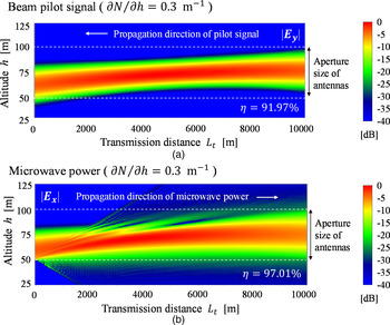
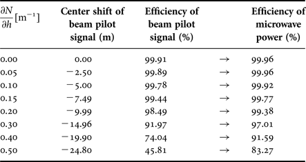
Figure 4 shows the electric field distributions of the beam pilot signal and microwave power with the gradient refractive index. The altitude of the bottom edge of the antennas was set as 50 m, which was above the meteorological surface layer. Figure 4(a) represents the electric field distribution of the beam pilot signal in the condition of ∂N/∂h = 0.3 m−1. It was shown that a small difference in the refractive index due to the altitude bends the direction of the beam in the terrestrial microwave power transmission. In this case, the amplitude center of the beam moved 14.96 m downwards and the transmission efficiency was degraded to 91.97%. Conversely, Fig. 4(b) shows the field distribution of microwave power in the case of ∂N/∂h = 0.3 m−1. The almost microwave power is returned to the receiving antenna area by conjugating the phase of the beam pilot signal, although the input area of the power-transmitting antenna is limited. In this case, transmission efficiency of 97.01% with respect to the microwave power was obtained.
Beam propagation characteristics in the gradient refractive index.

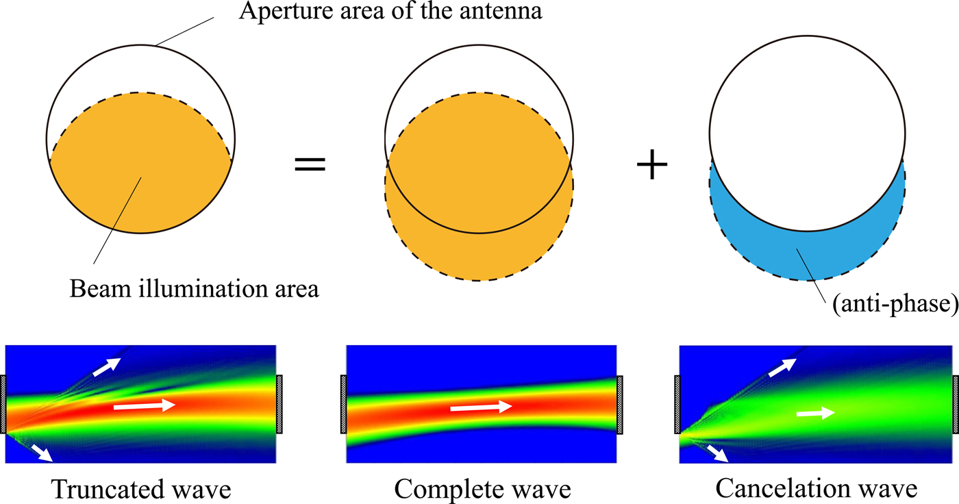
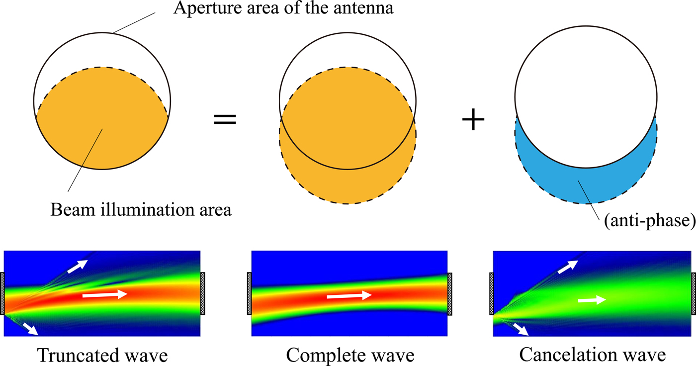
This efficiency was improved by approximately five points from that of the beam pilot signal. The improvement in the transmission efficiency with different refractivity gradients ∂N/∂h is summarized in Table 1. In the gradient refractive index, the intensity center of the beam pilot signal moved downward and transmission efficiency decreased. However, the degradation of the transmission efficiency of the microwave power was moderated by using the conjugating phase of the beam pilot signal. This improvement in the efficiency can be explained as follows. According to the radiation equation, the radiation wave truncated by a finite range of the transmitting antenna could be expressed as a superposition of the complete wave and the cancelation wave of the anti-phase as shown in Fig. 5. The cancelation wave completely canceled the complete wave outside the transmitting antenna. However, the cancelation wave diffused during propagation because the directivity of the cancelation beam with small aperture area was lower than that of the complete wave. The cancelation effect decreased on the receiving antenna surface. The improvement in transmission efficiency of the microwave power was then achieved.
Interpretation of the truncated wave as a superposition of the complete wave and the cancelation wave to understand the improvement in the transmission efficiency.
Improvement of transmission efficiency by beam pilot signal.

C) Collection effect of the beam pilot signal direction
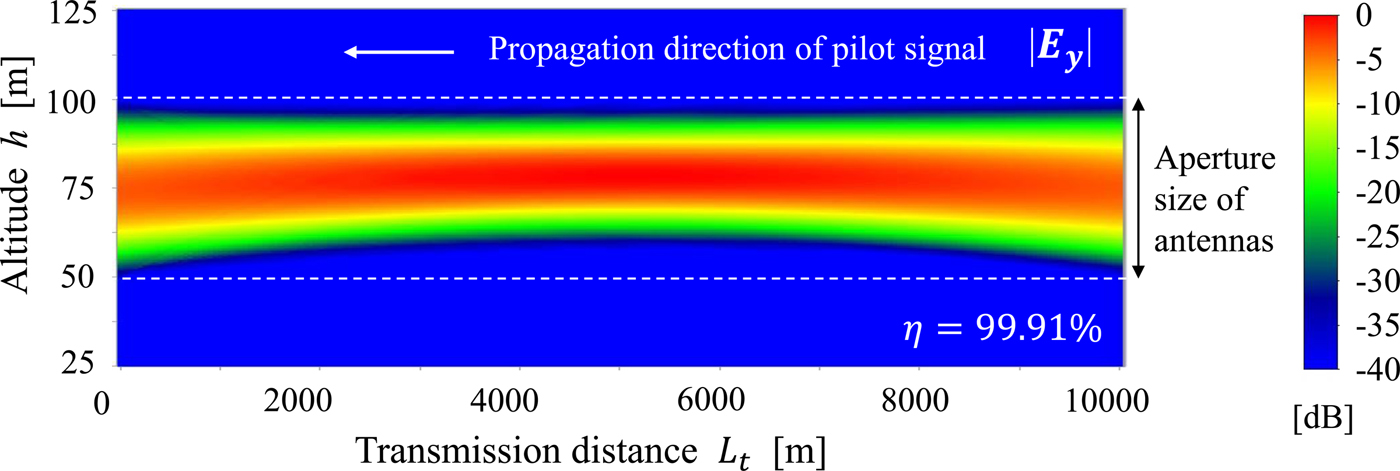
The radiation direction of the beam pilot signal was not controlled in the above simulation. By emitting the beam pilot signal in the appropriate direction, the transmission efficiency could be restored to the original value even when the fluctuated refractive index conditions changed over time. Figure 6 shows the electric field distribution of the beam pilot signal collected in the radiation direction. The gradient of the refractivity was set as ∂N/∂h = 0.3 m−1. The beam was initially radiated in the upward direction, and refracted in the downward direction while propagating. The inclination of the phase of the beam pilot signal was set as 10°/m. This was equivalent to the beam tilt angle of 0.082°. In this case, the transmission efficiency of the beam pilot signal was 99.91%, which was equal to the design value in the constant medium (∂N/∂h = 0.0 m−1). It was confirmed that the microwave power propagated through an approximately similar path with the beam pilot signal in the opposite direction.
Collected beam pilot signal under the gradient refractive index condition (∂N/∂h = 0.3 m−1).
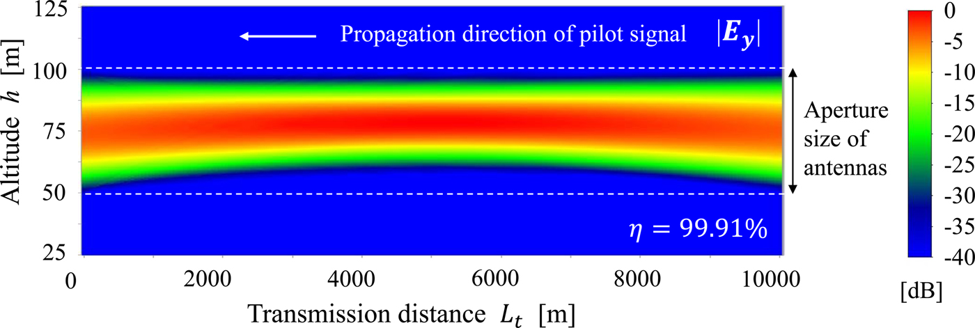
In this section, it was confirmed that the beam pilot signal and the microwave power can accurately share the propagation space. The collection method is required to radiate the beam pilot signal to the optimum direction. The beam direction of the pilot signal should be estimated from the phase and amplitude distributions of the microwave power. However, this is an issue that should be addressed in the future.
IV. DUAL-MODE DIELECTRIC RESONATOR ANTENNA ELEMENTS FOR SHARING THE BEAM PILOT SIGNAL AND THE MICROWAVE POWER
Degenerated dual-mode array antenna elements with high isolation levels were required to transmit and receive two orthogonal polarizations to realize a retrodirective system using the beam pilot signal as described in the previous section. The development of a dual-mode dielectric resonator antenna to share the beam pilot signal and microwave power is discussed in this section. A dual-mode antenna functions in a manner similar to that of the two isolated antennas shown in Fig. 2(b).
In this study, a hemispherical dielectric resonator antenna arranged on a large ground plane was proposed for the array antenna element. The outside field of the TE11-mode hemispherical dielectric resonator was identical to the field of infinitesimal magnetic dipole [Reference Matsumuro, Ishikawa and Shinohara33]. This implied that minimum mutual coupling of the hemispherical dielectric resonator was expected because the region of the resonant field was the smallest. Additionally, almost no mutual coupling by the surface wave mode of the substrate was observed. Thus, the hemispherical dielectric resonator antenna is suitable for the array antenna elements because mutual coupling is a major factor of the efficiency degradation of the phased array antenna. Furthermore, a cross-shaped structure is applied for the hemispherical dielectric resonator to isolate the two orthogonal modes, namely TE11x-mode and TE11y-mode with high isolation levels exceeding 60 dB as mentioned in Section II. It is considered that the cross-shaped structure improves isolation degradation caused by inhomogeneous of the dielectric material distribution that may occur during mass production.
This section discusses the development of a design method for the dual-mode dielectric resonator antenna with high isolation. The proposed antenna was first designed using an electromagnetic field simulator HFSS by the finite element method. Next, sensitivity analysis of the probe angle and the phase unbalance was examined. This was followed by investigating the measurement results of the isolation characteristics of a fabricated antenna element. The target isolation level of 60 dB was experimentally obtained. Finally, the mutual coupling between adjacent antenna elements was evaluated. It was shown that the mutual coupling of other antenna elements canceled against each other in the case of the square-arranged array antenna.
A) Design of cross-shaped hemispherical dielectric resonator antenna
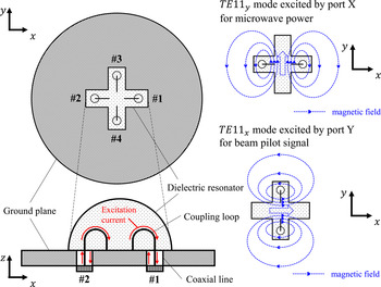
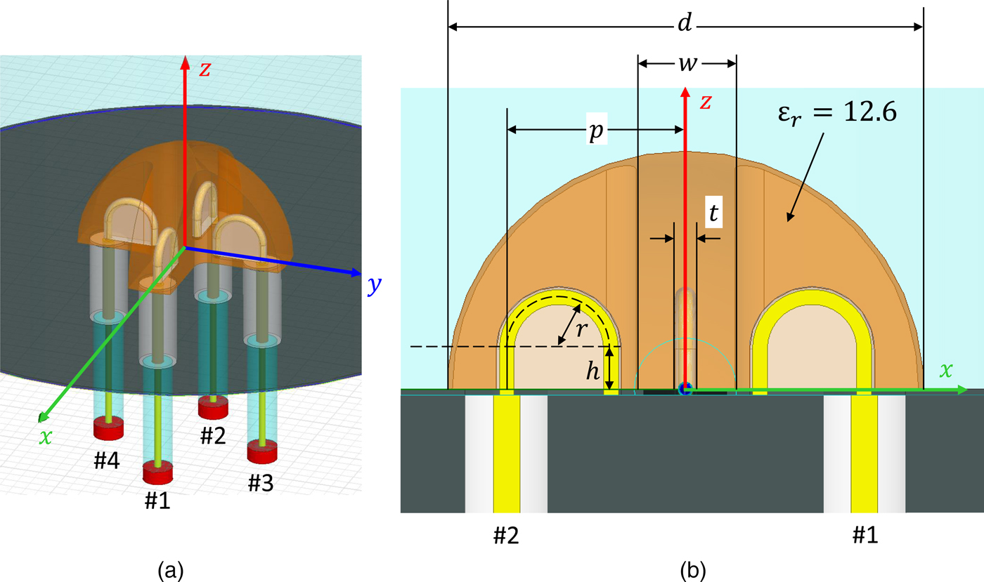
Figure 7 shows an overview of the dual-mode dielectric resonator antenna. The radiation element of the dual-mode dielectric resonator antenna comprised of a cross-shaped hemispherical dielectric resonator. Four coaxial lines were connected to the dielectric resonator by the magnetic coupling loop. The coupling loops were symmetrically arranged. Interport coupling by the floating capacitance was reduced by shorting the probe toward the center. Two single-ended coaxial lines were operated as a balanced port. The differential mode of coaxial lines #1 and #2 was termed as port X, and also the differential mode of coaxial lines #3 and #4 was termed as port Y. Ports X and Y were connected to TE11y-mode and TE11x-mode of the dielectric resonator, respectively. It was assumed that TE11y-mode and TE11x-mode were applied for the antenna element of the microwave power and the beam pilot signal, respectively.
Overview of the dual-mode dielectric resonator antenna element.

Figure 8 shows the simulation model of the dual-mode dielectric resonator with infinite ground. As shown in Fig. 8(a), the wave port for each coaxial lines was set and the four-port S parameter was obtained. The characteristics of the differential mode were evaluated by the conversion equation of the mixed-mode S parameters [Reference Huynh, Håkansson and Gong34]. For example, the transmission coefficient S YX is given by the following equation:
 $$S_{YX} = \displaystyle{{S_{31} - S_{32} - S_{41} + S_{42}} \over 2}.$$
Simulation model of the dual-mode dielectric resonator antenna with infinite ground (d = 16 mm, w = 3.3 mm, t = 0.7 mm, p = 6 mm, r = 1.75 mm, and h = 1.35 mm).
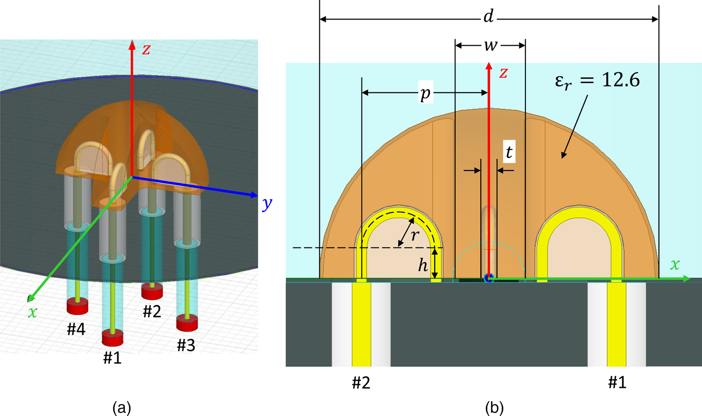
The dual-mode dielectric resonator antenna was designed by this simulation model. Figure 8(b) shows the design parameter of the configurations. A dielectric material was selected for the alumina ceramics. The relative permittivity of the material corresponded to 12.6. The dielectric Q of the material corresponded 20 700 at 5.8 GHz. The diameter of the dielectric resonator was 16 mm. The calculated radiation Q of the dielectric resonator was 23.6. Other design parameters of the dielectric resonator and the coupling probes are shown in Fig. 8(b).
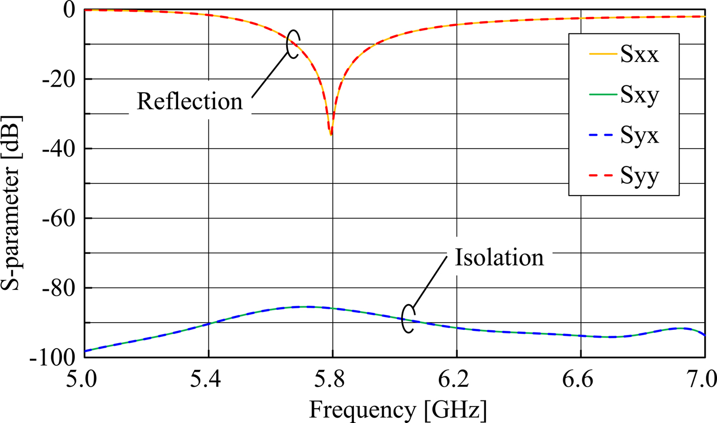
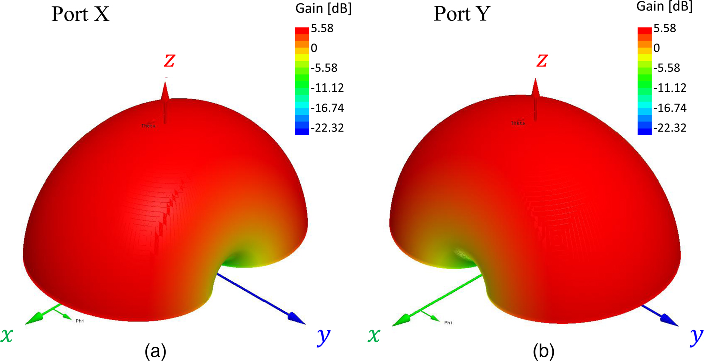
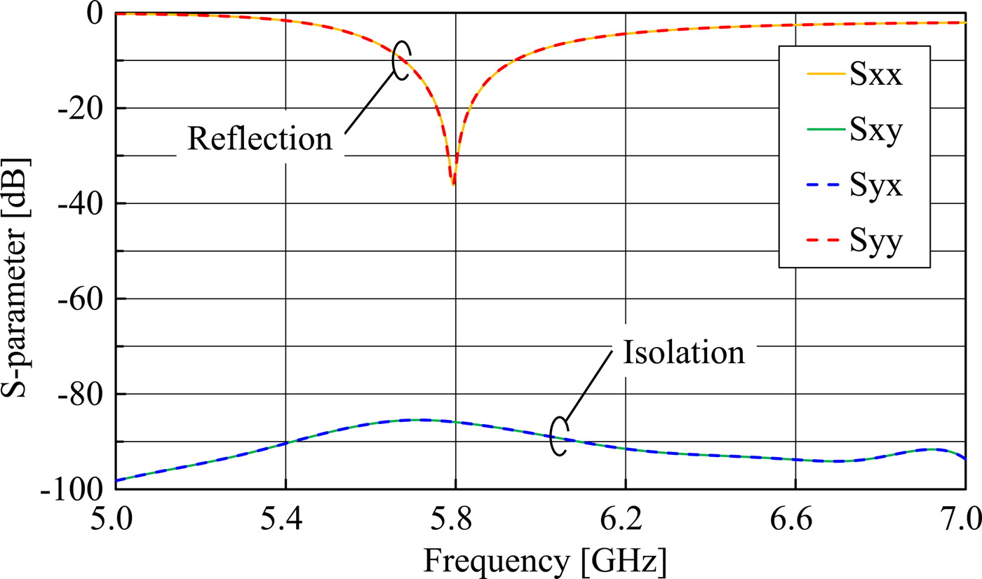
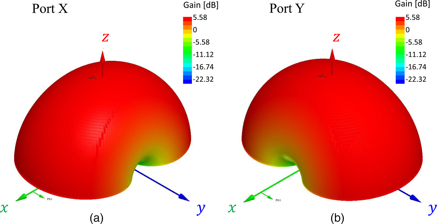
The input characteristics and the radiation pattern of the dual-mode antenna element were simulated by using this model. Figure 9 shows the simulation result of the reflection and transmission coefficient of the designed antenna. The parameter S comprised S XX , S XY , S YY was also calculated from the S parameter of four ports by the conversion equation of the mixed-mode S parameters as expressed in equation (3). Almost identical reflection characteristics were obtained in ports X and Y due to the symmetric structure. The reflection coefficients S XX and S YY corresponded −33.2 and −32.6 dB, respectively at 5.8 GHz. It was confirmed that the resonant frequencies of the TE11x-mode and the TE11y-mode were degenerated. Further, the transmission coefficient S YX corresponded to −85.91 dB. A sufficient isolation level could be designed. The radiation pattern of each port at the frequency of 5.8 GHz is shown in Fig. 10. It was observed that the radiation patterns of ports X and Y corresponded to 90° rotational symmetry with respect to the z-axis. It was confirmed from the figures that the TE11-mode was correctly excited by each port. Both gains in the front direction were 5.58 dBi.
Simulation results of the reflection coefficient and isolation of the designed dual-mode dielectric resonator antenna.
Radiation pattern of the cross-shaped dielectric resonator antenna in the simulation at 5.8 GHz.
B) Sensitivity analysis of the probe angle and the phase unbalance
High isolation exceeding 60 dB was confirmed in the simulation. However, it was expected that the isolation level depends on the manufacturing precision. The isolation degradation was then estimated by the manufacturing tolerances.
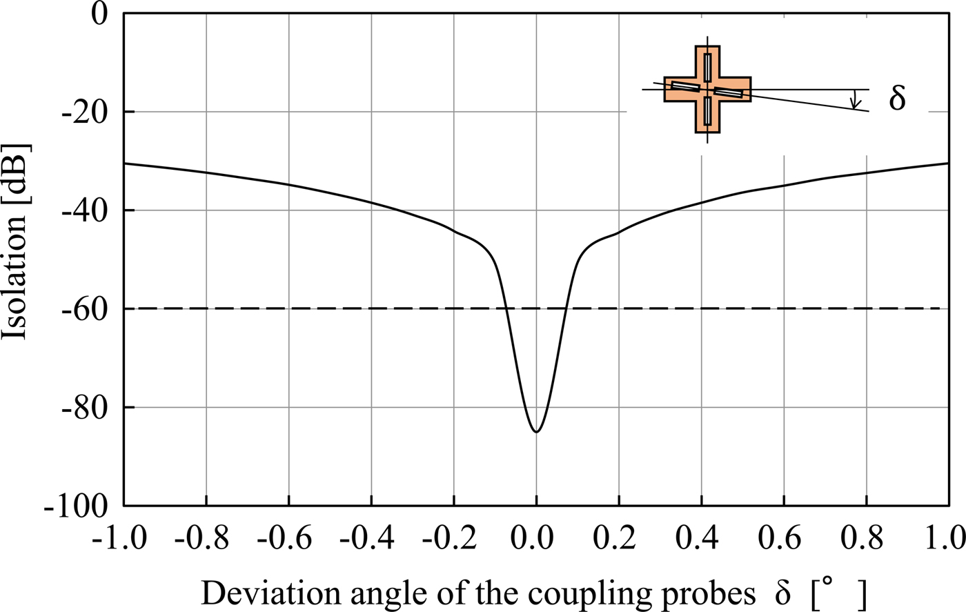
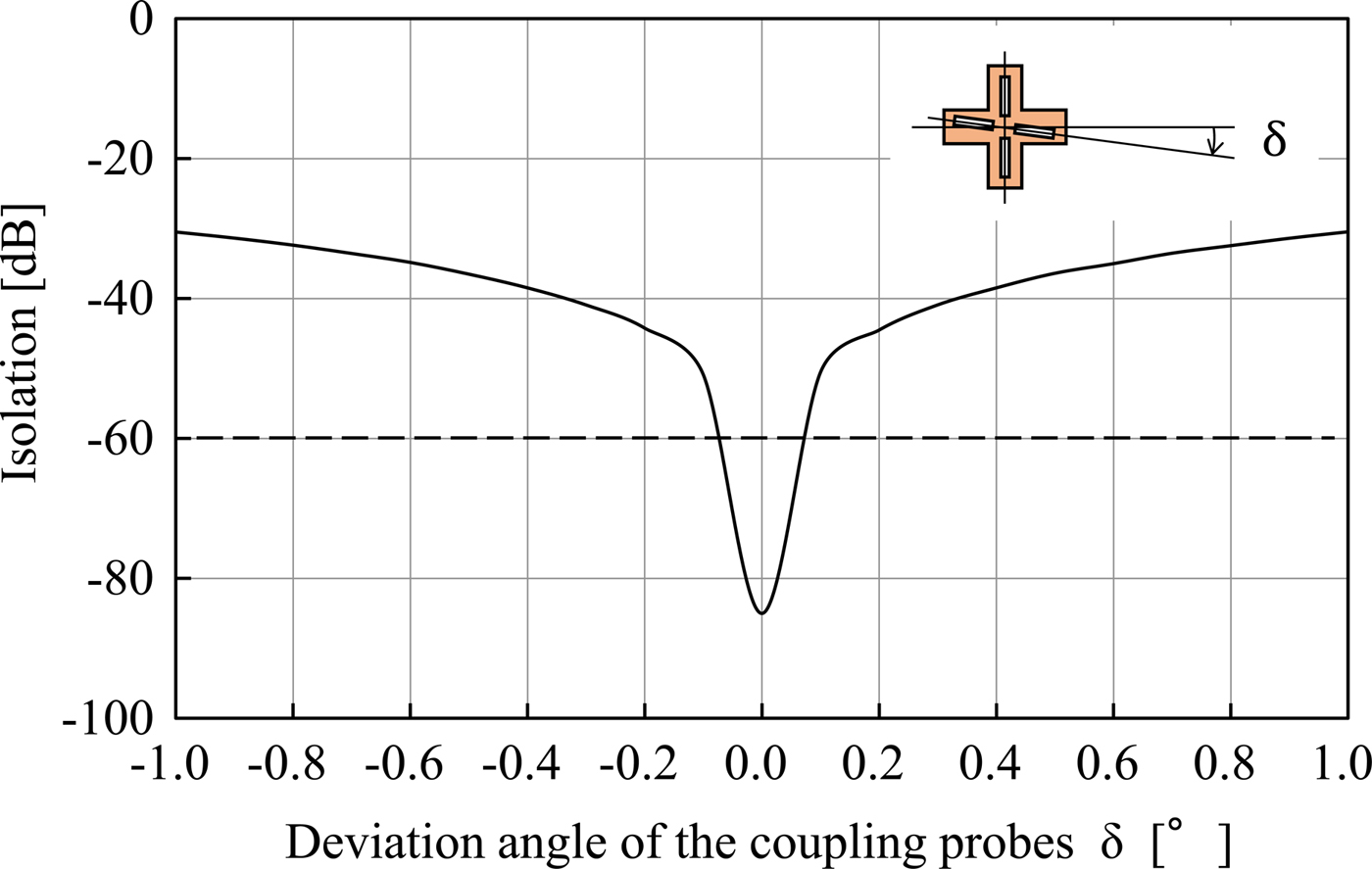
A serious manufacturing tolerance relates to the mechanical orthogonality of the coupling probes. Figure 11 shows the isolation degradation of the designed antenna simulated by changing the mechanical angle of the coupling probes. It was observed that the isolation level sensitively degraded as the absolute value of the deviation angle increased from 90°. In order to archive an isolation level exceeding the target value of 60 dB, it was necessary to keep the deviation angle within ±0.1°.
Isolation degradation by the deviation angle of the coupling probes.
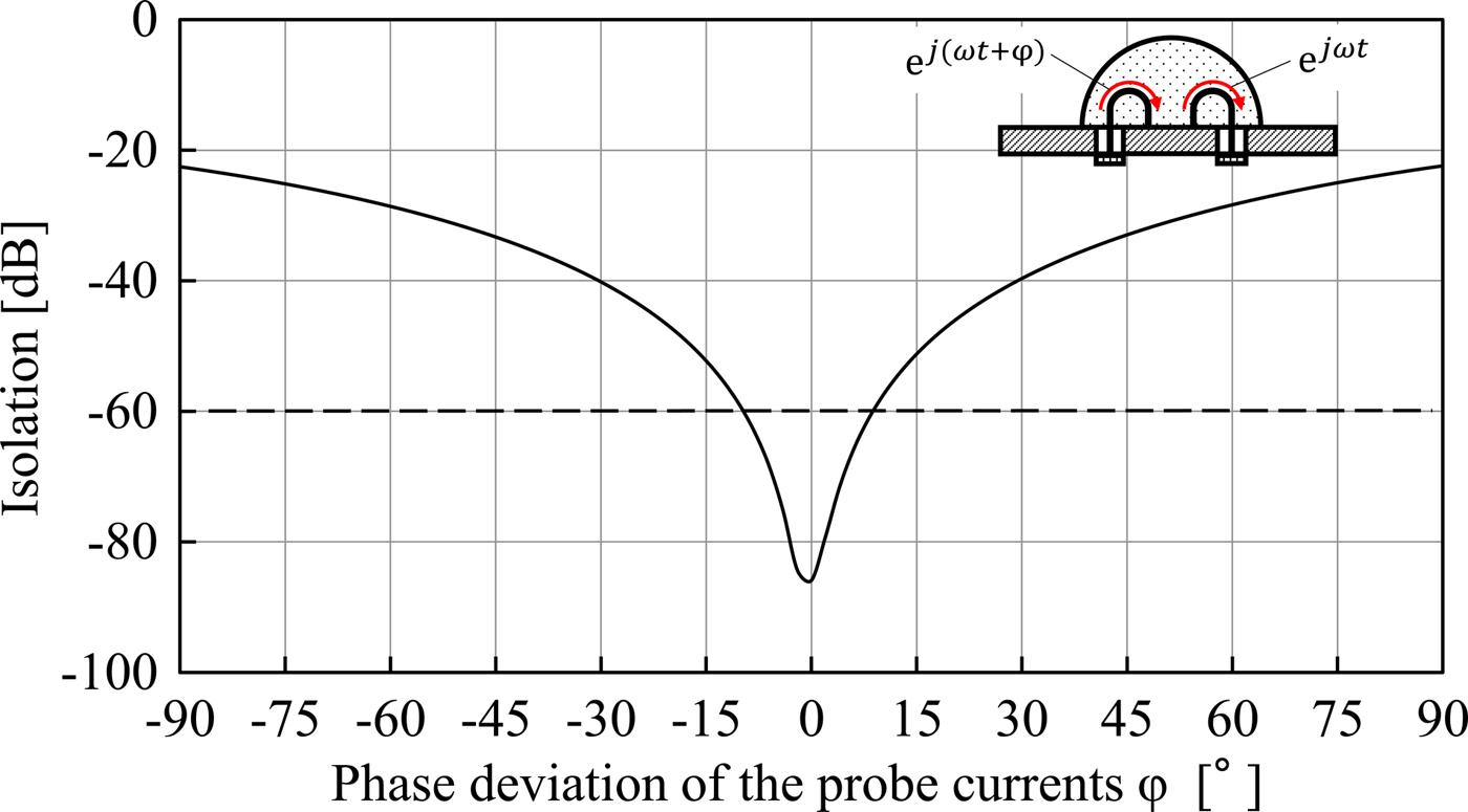
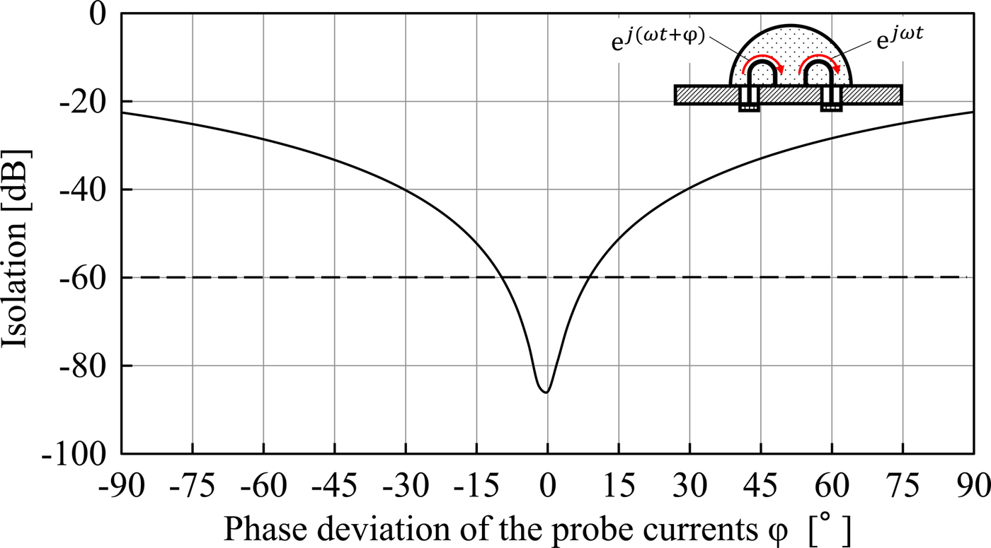
Another manufacturing tolerance includes the phase deviation of the input current of the differential mode. This type of isolation degradation was estimated by calculations involving the S parameters of coaxial four ports. In order to simplify the analysis, it was assumed that the phase deviation from the differential mode of ports X and Y is the same. In this case, the isolation degradation of the ports is expressed as follows:
 $$S_{YX} = \displaystyle{{S_{31} - S_{32} \; e^{j\varphi} - S_{41} \; e^{j\varphi} + S_{42} \; \; e^{j2\varphi}} \over 2}.$$
Figure 12 shows the isolation degradation of the designed antenna calculated by changing the phase deviation of the input current of the differential mode using equation (4). It was necessary to keep the phase deviation of the input current within ± 10° to archive the isolation level over the target value of 60 dB.
Isolation degradation by the phase deviation of the differential mode.
C) Measurement experiment of a fabricated antenna
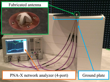
The designed dual-mode dielectric resonator antenna was fabricated and measured. Figure 13 shows an external view of the fabricated antenna and the configuration of the measurement experiment. The sphericity of the fabricated dielectric resonator corresponded to 55 µm over the diameter of 16 mm. The hemispherical dielectric resonator was bonded to a copper-plated metal plate with a thickness of 0.3 mm. The dielectric resonator with metal plate was fixed to a sufficiently large aluminum ground with a diameter of 150 cm. The coupling probe was a beryllium copper metal wire with a thickness of 0.5 mm with a U shape. Four coupling probes with a Teflon seal of 80 µm thickness were inserted into the slit of the dielectric resonator. The four coaxial cables were connected from the coupling probes to the four-port vector network analyzer from Agilent Technology (N5242A). The network analyzer was calibrated by an electronic calibration kit (N4691B). The center frequency was set as 5.8 GHz, the span as 2 GHz, and the step as 10 MHz, using a smoothing function of 1.5% to the span (30 MHz). The input signal level was set as −5 dBm. The temperature of the anechoic chamber corresponded to 22°C and the humidity was 39%.
Configuration photograph of the antenna measurement experiment.

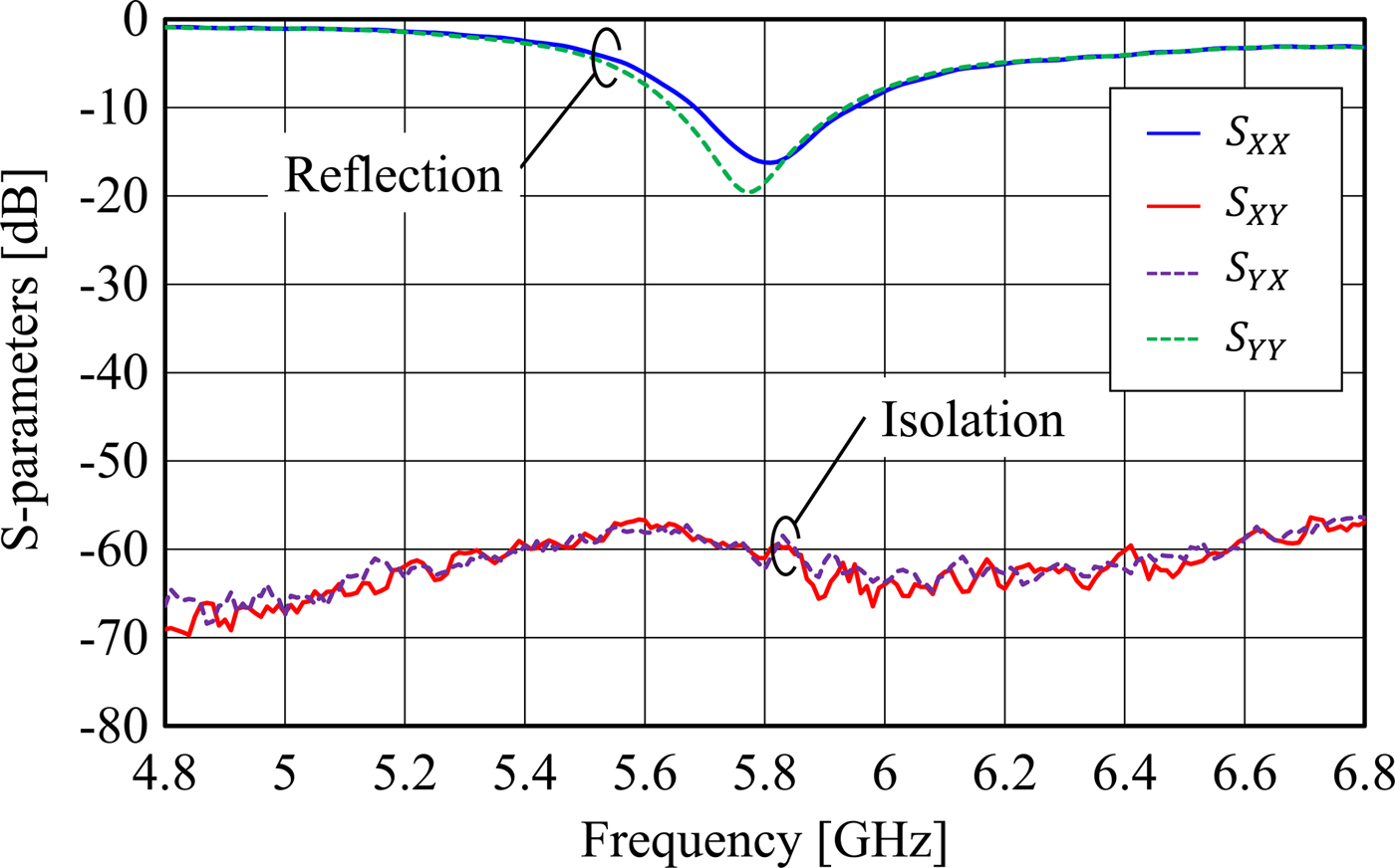
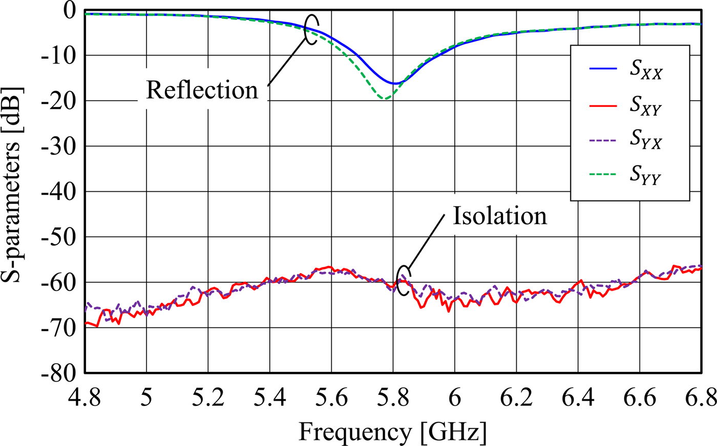
Figure 14 shows the measurement results of the reflection coefficient and isolation of the fabricated antenna. The reflection coefficients S XX and S YY corresponded to −16.2 and −18.4 dB at 5.8 GHz. The resonant frequency of the TE11x-mode excited by port Y was lower than that of the TE11y-mode of port X. This was because the electric field perturbation of the coupling probe of the port Y was slightly large. It was assumed that the two resonance frequencies coincided when the areas of the coupling probe of each ports were equal. The transmission coefficient S YX corresponded to −62.24 dB, which satisfied the target isolation value to realize the proposed retrodirective system. Thus, it was confirmed that a degenerated dual-mode dielectric resonator was constructed.
Measurement results of the reflection coefficient and isolation of the fabricated antenna.
D) Cancelation of the mutual coupling between adjacent antenna elements
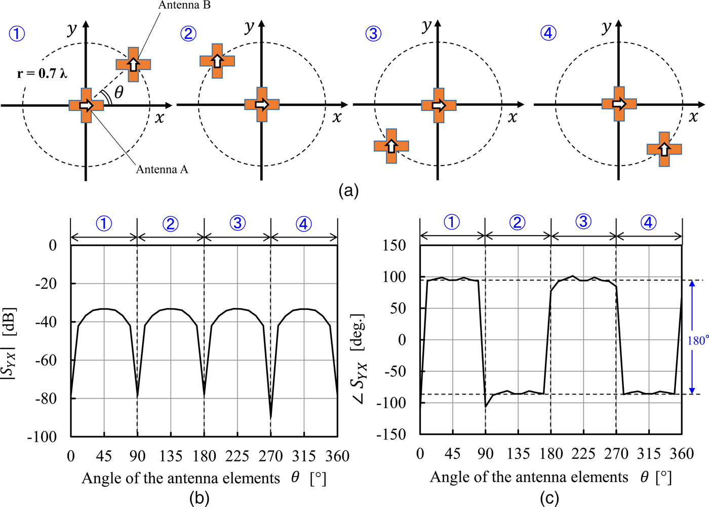
In the previous section, sufficient isolation was obtained between the orthogonal ports of a single antenna element. Meanwhile, it was necessary to consider isolation degradation due to mutual coupling between adjacent antenna elements in the case of array antenna. In this section, the mutual coupling between port X of the microwave power of an antenna and port Y of the pilot signal of another antenna was evaluated.
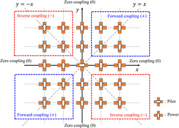
Figure 15 shows the simulation result of the isolation between two antenna elements. The isolation between port X of antenna A and port Y of antenna B was evaluated by changing the angle of the antenna elements from 0° to 360°. The design parameter of the antenna elements was the same as the simulation of the single element. The distance of the two antenna elements was set as 3.62 cm (0.7 wavelength at 5.8 GHz). The absolute value and the phase of the transmission coefficient are shown in Figs 15(b) and 15(c), respectively. Although the absolute value was below −60 dB at 0°, 90°, 180°, and 270°, it increased with respect to other angles. The largest observed value corresponded to −33.2 dB at 45°, 135°, 225°, and 315°. However, it was observed that the phase of the transmission coefficient was reversed in each quadrant. It was expected that the summation of four types of mutual coupling would be zero.
Simulation results of the transmission coefficient between adjacent antenna elements.
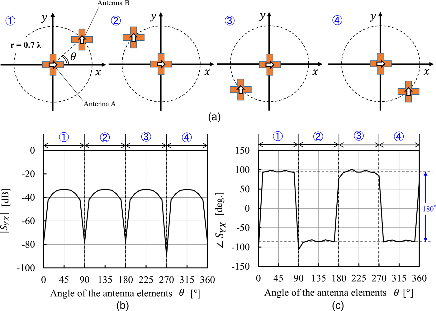
Several TE11y-mode resonators for microwave power were arranged around an arbitrary TE11x-mode resonator for the pilot signal in the case of the practical condition of the planar array antenna. We examined a layout design of antenna elements to cancel the mutual couplings of the pilot signal and microwave power based on the simulation results of two elements. Figure 16 shows the schematic illustration of the square-arranged array antenna. The central antenna represents any pilot signal antenna of interest. According to the simulation results shown in Fig. 15, the mutual couplings to the center resonator from the resonators on the x axis and the y-axis were almost zero. Moreover, the mutual couplings of the resonators on the line y = ±x were completely canceled at the center resonator. This indicated that the isolation of the resonators in the nearest neighbor was maintained. The same relationship was satisfied to the mutual coupling of any antenna for the microwave power and the surrounding antennas for the pilot signal. It could be inferred that isolation between the port of the microwave power and the pilot signal was evaluated by only that of a single antenna element. Then, it could be concluded that the pilot signal and the microwave power were isolated as the whole array antenna even in the case of using all antenna elements to transmit/receive the pilot signal and microwave power.
Estimation of the mutual coupling between an arbitrary antenna for the pilot signal and the surrounding antennas for the microwave power.

V. CONCLUSION
In this study, a single-frequency retrodirective system with a beam pilot signal was proposed using dual-mode dielectric resonator antenna elements for terrestrial microwave power transmission.
First, the configuration of the retrodirective system with a beam pilot signal was discussed. In this system, a beam pilot signal with the same frequency as microwave power was emitted from the entire surface of the receiving antenna to avoid multipath propagation and frequency dependence of the refractive index. Vertical and horizontal polarizations were applied to distinguish between the pilot signal and the microwave power, respectively.
The operation of the retrodirective system with a distance of 10 km through the gradient refractive index was then simulated by the BPM. A few influences of the ground were estimated in the case of the proposed beam pilot signal from the entire area of the power-receiving antenna. It was confirmed by conjugating the phase of the pilot signal that the microwave power had essentially the same distribution as that of the pilot signal. It was shown that the transmission efficiency of the microwave power was relatively maintained even when the transmission efficiency of the beam pilot signal was low.
Additionally, a dual-mode dielectric resonator antenna as an array antenna element for sharing the beam pilot signal and microwave power was proposed and discussed. Isolation exceeding 60 dB was experimentally obtained with a cross-shaped hemispherical dielectric resonator. Simulating the mutual coupling between different antenna elements indicated that the isolation between the port of the pilot signal and microwave power could be evaluated by that of a single antenna element. This suggested that the beam pilot signal and the microwave power were isolated in the whole array antenna.
Hence, this study successfully developed a dual-mode dielectric resonator antenna with an isolation exceeding 60 dB. This is an important device to realize a single-frequency retrodirective system with a beam pilot signal. The proposed retrodirective system is expected to improve the reliability of terrestrial microwave power transmission. Cost reduction of the power transmission system can also be expected due to the simplification of the power transmission circuit. A future study will examine the collection method of the beam direction of the pilot signal and the development of the circuit module.
ACKNOWLEDGEMENTS
This research was supported by the Japan Society for the Promotion of Science, Grant-in-Aid for JSPS Fellows 14J05138. The authors would like to thank Dr. Takaki Ishikawa and Mr. Akiyoshi Ono of Orient Microwave Corp. for the fabrication of the dual-mode dielectric resonator antenna elements. Antenna measurements were conducted through a collaborative research program: Microwave Energy Transmission Laboratory (METLAB), at Research Institute for Sustainable Humanosphere, Kyoto University.
 Takayuki Matsumuro was born in 1988. He received the B.E. and M.E. degrees in Electrical Engineering from Kyoto University, Kyoto, Japan, in 2012 and 2014, respectively. He has been a Ph.D. student in Electrical Engineering from Kyoto University and a Research Fellow for Young Scientists (DC1) of Japan Society for the Promotion Science since 2014. He has been engaged in research on microwave power transmission. He was awarded the Best Presentation Award in Thailand–Japan Microwave Conference 2013. He is a member of the IEEE and the Institute of Electronics, Information and Communication Engineers (IEICE).
 Yohei Ishikawa received the M.E. degree in Physics from Nagoya University, Aichi, Japan, in 1972. He received the Ph.D. degree in Communication Engineering from Tohoku University, Sendai, Japan, in 1994. He worked for Murata Manufacturing Co., Ltd. from 1972 to 2011. He was awarded the APMC Japan Microwave Prize in 1994 and the Commendation for Science and Technology by the Minister of Education, Culture, Sports, Science and Technology in 2006. He has been a professor in Research Institute for Sustainable Humanosphere, Kyoto University, Kyoto, Japan, since 2009. He was chair of IEEE Microwave Theory and Technique Society (MTT-S) Kansai Chapter from 2010 to 2013. He is the founder and president of the Kaiyo Inverse Dam Society (KID-S). He is chair of Technical Committee on Microwaves, Electronics Society, in the Institute of Electronics, Information and Communication Engineers (IEICE). He is a fellow of the IEICE, and a member of the IEEE.
 Tomohiko Mitani received his B.E. degree in Electronic Engineering, his M.E. degree in Informatics, and his Ph.D. in Electrical Engineering from Kyoto University, Kyoto, Japan, in 1999, 2001, and 2006, respectively. He was an Assistant Professor with the Radio Science Center for Space and Atmosphere, Kyoto University, in 2003. He has been an Associate Professor with the Research Institute for Sustainable Humanosphere, Kyoto University, since 2012. His current research interests include microwave heating application and microwave power transfer. He has been a board member of Japan Society of Electromagnetic Wave Energy Applications (JEMEA), and a treasurer of IEEE MTT-S Kansai Chapter since 2014.
 Naoki Shinohara received the B.E. degree in Electronic Engineering, the M.E. and Ph.D. (Eng.) degrees in Electrical Engineering from Kyoto University, Japan, in 1991, 1993, and 1996, respectively. He was a research associate in the Radio Atmospheric Science Center, Kyoto University from 1996. He was a research associate of the Radio Science Center for Space and Atmosphere, Kyoto University by recognizing the Radio Atmospheric Science Center from 2000, and there he was an associate professor since 2001. He was an associate professor in Research Institute for Sustainable Humanosphere, Kyoto University by recognizing the Radio Science Center for Space and Atmosphere since 2004. From 2010, he has been a professor in Research Institute for Sustainable Humanosphere, Kyoto University. He has been engaged in research on Solar Power Station/Satellite and Microwave Power Transmission system. He is IEEE MTT-S Technical Committee 26 (Wireless Power Transfer and Conversion) vice chair, IEEE MTT-S Kansai Chapter TPC member, IEEE Wireless Power Transfer Conference advisory committee member, International Journal of Wireless Power Transfer (Cambridge Press) executive editor, technical committee on IEICE Wireless Power Transfer, communications society member, Japan Society of Electromagnetic Wave Energy Applications vice president, Space Solar Power Systems Society board member, Wireless Power Transfer Consortium for Practical Applications (WiPoT) chair, and Wireless Power Management Consortium (WPMc) chair.
 Masashi Yanagase received the B.E. and M.E. degrees in Electrical Engineering from Nagoya University, Japan, in 1990 and 1992, respectively. From 1992 to 2000, he was a member of technical staff with Omron Corporation, Kyoto, Japan, and participated in the development of semiconductor optoelectronic devices. Since 2000, he has joined Murata Manufacturing Co., Ltd., Kyoto, Japan, and pursued in the new devices of renewable energy field. He is currently a principal researcher with New Process Engineering Development Department. He is a member of the Japan Society of Applied Physics (JSAP), the Institute of Electronics, Information and Communication Engineers (IEICE), and the Institute of Electrical and Electronics Engineers (IEEE).
 Mayumi Matsunaga received B.E., M.E., and Dr.Eng. degrees in Computer Science and Communication Engineering from Kyushu University, Japan. While she was a Ph.D. student, she studied electromagnetic theories at the University of Wisconsin-Madison. She received the Young Engineers' Award from IEICE in 2001. In 2007, she stayed in the University of Washington as a visiting scholar. She won the NE Japan Wireless Technology Award in 2013. Her current research fields are inventing novel antennas, analyzing EM propagation, and designing microstrip circuits. She is now with the Tokyo University of Technology. She is a member of IEEE, IEICE, and ASJ.