





Impact statement
Condition-based maintenance is increasingly being considered for maintaining the structural reliability of naval vessels, as it may improve the operational availability of vessels while simultaneously saving on maintenance costs or allowing for lifetime extension. But practical implementation of structural condition-based maintenance is still a challenge mainly because of the competing desires which can direct toward different maintenance strategies, the wide-ranging necessity for general to detailed information that different stakeholders are seeking, continuing challenges and open questions in environment and damage monitoring and prognosis, and different choices for parameter sensing. This paper presents a unique end-to-end perspective of structural condition-based maintenance for naval vessels, based on foundational and state-of-the-art literature and the practical experience of partners implementing structural monitoring solutions onboard such vessels. The resulting “baseline” structural health monitoring sensor system for condition-based maintenance offers a solution for practical implementation onboard naval vessels and calls for directed future research areas which should be further developed to facilitate such implementation.
1. Introduction
The hulls of Navy ships are subject to wave loading and corrosion degradation as they operate under harsh dynamic loading and stochastic environmental conditions with varying mission requirements. Despite extensive experience in the design and analysis of these structures, large uncertainties introduced at different stages of vessel fabrication (e.g., initial quality of the material and welds) and operation (e.g., loading history and environmental conditions) still impede a completely accurate prediction of extreme loads, fatigue accumulation, and corrosion. These uncertainties can increase the probability of incidents, reduce the efficiency of inspection and maintenance planning, and/or increase the lifecycle costs needed to mitigate lifetime risk. Considering damage accumulation in a probabilistic framework allows the assessment of structural reliability, relating to determined and experienced risk levels and return periods to failure. Monitoring systems that can accurately, reliably, and quantitatively identify and monitor the accumulation of fatigue and corrosion damage in navy ships are highly desired but do not exist fully to date. These monitoring systems can be beneficial in several aspects, such as making maintenance or end-of-lifetime decisions, aiding in event reconstruction, and possibly enabling better future designs.
In condition-based maintenance (CBM), maintenance activities are initiated because they are prompted by a (suspected) degraded condition of the system, as opposed to waiting to perform maintenance after a failure has already occurred, or performing maintenance potentially before any action is needed (Kothamasu and Huang, Reference Kothamasu and Huang2007). To define a system for implementing structural CBM onboard naval vessels, the major aims of such monitoring must first be decided. Vessels can be outfitted with many sensors, leading to many estimates, resulting in ever larger amounts of data to analyze. But unlimited data do not lead to better maintenance decisions, especially for short-term (near real-time) actions. Therefore, the CBM system not only consists of hardware but also requires specifications on data analysis procedures to ensure that the most useful information is eventually presented to end-users. To define the CBM system, the first questions to consider are as below; we already offer our answers to these questions to motivate the naval CBM paradigm envisioned in this paper:
-
• What are the desired outcomes from implementing CBM? Our desired outcome is to support a naval vessel to safely and effectively complete its mission, even with structural degradation. Crew onboard and support onshore should be able to operate and direct the vessel with an understanding of the underlying structural risk. The CBM system should be able to sense the initiation of important structural damage to make both short-term decisions (hours–days), which should be taken by the crew on-board based on locally generated warnings, and long-term (fleet management) decisions (months–years), which can be used for lifecycle and fleet management.
-
• What outputs from the CBM system are the most important to achieve or support those outcomes? The CBM system should globally identify and localize the beginnings of problem areas to be further investigated via more targeted monitoring or inspection. The system should further be able to indicate the risk level of those areas and estimate the probability that the damage will lead to failure based on different operating scenarios. The CBM system should be able to give a general warning level to the crew about the structural integrity (for short-term decisions) and more detailed descriptions to onshore support for lifecycle management (long-term decisions).
It should be noted that different possible CBM outputs, such as values, figures, plots, or estimates, should be of a limited number to effectively communicate the relevant information. However, the definition of the most useful information will change depending on the different stakeholders, such as governments/Ministry of Defense (MoD), crew members, and system/maintenance planners (e.g., onshore engineers). These users will have different goals and needs, but they will all provide some important input in the maintenance process. The main points of interest for these parties may include the following:
-
• Governments/MoDs: battle/operational readiness from a fleet perspective, state of system (presented and projected future), guidance for optimal operation, and summaries of technical reports
-
• Crew members: immediate/real-time alerts based on current structural status for a specific vessel (e.g., survivability advice, indication to reduce speed or change course), failure indicators, and operational abilities
-
• System/maintenance planners: risk and opportunities associated with delayed maintenance schedules and operational capabilities given potentially degraded structural integrity, again from a fleet perspective
Note that to implement a “full” CBM system would require also considering other onboard systems such as HVAC, pumps, chillers, and engines, which is beyond the (structural) scope of this paper. This paper then considers CBM for the vessel structure based on the structural reliability, structural damage, and structural integrity as defined:
-
• Structural reliability: The survival probability (i.e., non-failure) for either individual components or the system as a whole.
-
• Structural damage: The system is at a degraded state when compared to its original/designed state, leading to lower reliability.
-
• Structural integrity: The system is fit-for-purpose to function at designed operational levels, considering parameters such as strength, stability, safety, and performance.
For naval vessels to carry out their missions safely and efficiently, maintaining structural integrity is of utmost importance. Therefore, it is necessary to determine the probability of structural deterioration/failure of the ship’s components and systems under short-term mission situations. Degraded structural integrity can have cascading effects on other capabilities, such as (damage) stability. Different maintenance strategies can be used to ensure that the structural integrity remains at a high-enough level for the vessel to continue operating. Then, it is possible to assess the ability of the vessel to withstand the design and operational loads while considering the uncertainties associated with them as well as with the structure itself (material, loading, design, etc.). When further combined with a decision framework that incorporates uncertainties, such as based on risk and total ownership cost (Stambaugh, Reference Stambaugh2020), structural CBM can be achieved.
1.1. What makes naval vessels (and their maintenance) different?
This paper considers structural CBM for naval vessels. But it should be noted that many of the structural condition monitoring and maintenance principles examined here are also technically relevant for commercial vessels, as well as the offshore industry, and more broadly for aerospace, civil structures, and so forth What then makes naval vessels (and their structural maintenance) special? At least in terms of distinction from commercial vessels and the offshore industry, the main differences stem from the aims in mission/operational demands, the influence of regulation frameworks, and the ownership paradigm.
Naval vessels have missions set by MoDs, with variable deployments that can already be long and then further extended on short notice. Naval vessels must carry out their mission despite rough weather, and they may not simply be able to reduce speed or change course to reduce structural loading. Due to their unpredictable usage profile, naval vessels can have uneven fatigue consumption based on the alternating periods of deployments, maintenance, and refit. Naval vessels thus do not evenly use their fatigue lifetime and are not tied to time-based maintenance intervals, so CBM can be a useful strategy. The main aims for naval vessels are to ensure survivability for the crew onboard and maintain mission readiness, possibly at the expense of smaller maintenance activities which may be delayed due to mission needs or deployment extension. In that sense, an important question for naval crew is: are there significant structural damages present in the ship? What is the likelihood these damages lead to larger failures during a mission? These are the short-term decisions referenced in our answer for the desired outcomes for implementing CBM, above. Local on-board systems are needed for naval vessels to analyze sensed data and support crew in (near) real-time decision making to ensure sufficient structural integrity. For long-term (fleet management) decisions, estimating the fatigue usage of a vessel is important for possibly extending a vessel’s design life, even if that means costly repairs. For fleet-management decisions over a long timeline, such costly lifetime extensions may be worth it from the overall fleet perspective. Additionally with CBM, individual ship maintenance periods can be better scheduled to optimise fleet level availability and costs.
On the other hand, commercial vessels usually have regularly scheduled working intervals and operations are driven by profitability. These vessels can make use of weather-routing to avoid rough conditions, making the short-term maintenance decisions, like required for naval mission operability, less relevant. In this sense, time-based maintenance, as also recommended by many equipment manufacturers, is not necessarily a bad thing, as proper planning for maintenance intervals can reduce unexpected downtime to maximize profit. Commercial vessels, as opposed to naval vessels, also follow the classification societies’ lead, where guidelines concerning CBM are slowly coming online, but in general following the lead of industry, and still as an aid to, rather than a replacement of, time-based inspections. As noted in a review on implementing smarter maintenance strategies in the maritime field from the classification society perspective: “Based on the current review of Class related documents, physical surveys will not be replaced any time soon. Instead, the physical surveys will be more efficient and targeted” (Liang et al., Reference Liang, Knutsen, Vanem, Æsøy and Zhang2024). In this sense, the real-time condition monitoring (CM) linked with CBM is not as useful if scheduled physical surveys remain the major paradigm.
A final distinction between naval and commercial vessels, which makes CBM more meaningful for naval vessels, is the differences in ownership. Naval vessels almost always stay with their original owner (the navy) over their entire lifetime. In that sense, upfront investments to track the vessel condition for maintenance planning in accordance with changing operational demands makes sense. Naval owners are thinking over the vessel lifetime and from a fleet perspective. But commercial vessels are less likely to stay with the same owner over their lifetime, making the initial investment in a structural CM system for lifetime management, and the lifetime payback via more informed maintenance decision making, less attractive. Therefore, the technologies enabling CBM are not necessarily specific to naval vessels, but there is a clearer motivation for implementing CBM for naval vessels.
1.2. Paper composition
This paper presents a review of both foundational and state-of-the-art literature corresponding to the different aspects of structural CBM for naval vessels. Of course, there are many noteworthy recent reviews on ship structural health monitoring; see, for example, Sindi et al. (Reference Sindi, Kim, Yang, Thomas and Paik2024), Mandal et al. (Reference Mandal, Roy and Ghoshal2026), and Pezeshki et al. (Reference Pezeshki, Adeli, Pavlou and Siriwardane2023). This particular review considers the foundational and recent advances in ship structural health monitoring specifically from the naval vessel perspective. While many of the technologies remain relevant across the commercial maritime sector and farther into civil structures and aerospace, the naval focus of this review has the dual aim of suggesting a baseline naval structural health monitoring sensor system for condition-based maintenance onboard naval vessels while pointing out areas of future research which are further needed to achieve this monitoring paradigm. Such naval monitoring is further distinguished based on the main differences regarding naval vessel maintenance discussed in Section 1.1 and the long- and short-term decisions which are also special for naval vessels.
The review is organized as follows: first Section 2 defines possible maintenance strategies, Section 2.5 defines the aims of CBM for naval vessels, and Section 2.6 describes the system architecture for an onboard CBM system. This architecture comprises six modules which are then discussed in the paper: data acquisition (Section 3), data manipulation (Section 4), state detection, also referred to as condition monitoring (Section 5), health (diagnostic) assessment (Section 6), prognostic assessment (Section 7), and advisory generation, also referred to as decision support (Section 8). Based on the state-of-the-art literature and experience and lessons learned from three noteworthy previous monitoring campaigns performed by the paper authors, discussed in Section 9, a baseline minimum sensor system for structural CBM of naval vessels is defined in Section 10. Finally, Section 11 concludes with final reflections and calls for further targeted research.
2. Maintenance motivation and possible strategies
Assessing the structural damage accumulating on naval vessels is challenging and is further complicated by the stochastic nature of ocean excitation. Maintenance activities to repair non-battle structural damage will be needed over the vessel’s lifetime, but when these activities occur and how they are initiated depends highly on the overall maintenance strategy. This strategy can be defined by several aims, which may have complementary or competing ends. Such possible aims include the reduction of maintenance costs, increase in operational availability, increase in safety, optimisation of operational performance, and possible extension of vessel service lifetime. Depending on which of these aims is ranked as the “most important,” or based on some weighting which balances these aims, a specific maintenance strategy can be defined.
Smart maintenance strategies have become tightly linked with readiness capabilities, where delayed maintenance activities have caused serious issues with vessel availability. In a Government Accountability Office report presented to the United States Senate Subcommittees on Seapower and Readiness and Management Support (Committee on Armed Services), it was noted that between (fiscal years) 2014 and 2019, United States Navy ships spent 33,700 more days in maintenance than expected (United States Government Accountability Office, 2019). The same report noted that 75% of the naval maintenance activities were not completed on time, and that there were “persistent and substantial maintenance delays that affect the majority of its maintenance efforts and hinder its attempts to restore readiness.” Clearly, smart maintenance strategies, and only performing maintenance activities when really needed, are of utmost importance to maintain naval asset readiness.
Maintenance strategies are either reactive or proactive by definition, where proactive activities may be either preventative or predictive in nature, and these strategies lead to different levels of “success” in terms of possible maintenance aims (e.g., reduction of maintenance costs, increase in operational availability, increase in safety, optimisation of operational performance, and possible extension of vessel service lifetime). Key elements in asset integrity management (AIM) are inspection, maintenance, and repair, where strategies have in general gone through the following five stages:
-
1. Breakdown maintenance in the 1940s (Barlow and Hunter, Reference Barlow and Hunter1960),
-
2. Preventive maintenance based on detection of degraded components in the 1960s (Barlow and Proschan, Reference Barlow and Proschan1965),
-
3. Reliability-based maintenance in the 1970s to 1980s (Andreou and Marks, Reference Andreou and Marks1987),
-
4. Reliability-based design and preventive maintenance based on mathematical modeling in the 1990s (Abdel-Hameed, Reference Abdel-Hameed1995),
-
5. Risk-based design and preventative maintenance in the 2000s (Khan et al., Reference Khan, Haddara and Bhattacharya2006).
The history of ship structural maintenance began with reactive (breakdown) maintenance and has been slowly progressing toward more proactive strategies (Lazakis et al., Reference Lazakis, Turan and Aksu2010). With the progression of onboard sensor technologies and the advanced modeling and analysis techniques (especially concerning the advent of machine learning [ML]/artificial intelligence [AI]) needed to analyze such data, AIM for naval vessels can be realized within a CBM paradigm.
2.1. Reactive maintenance
Reactive maintenance is generally the least-desirable maintenance option because action is taken only after failure occurs. For critical components of naval vessels, this could mean a loss of operational availability at an unexpected moment, which is a potentially unacceptable outcome. Such an unexpected failure could have a strong negative impact on vessel safety. In addition, fixing structural problems only after they occur may lead to higher maintenance costs, related to higher shipyard fees due to urgency and separated maintenance activities to fix individual issues that (might have) been instead fixed together. For small structural problems, reactive maintenance may be acceptable, as long as the structural damage is monitored, though reactive maintenance is now generally avoided as the overarching strategy for strategic structural components.
2.2. Proactive maintenance
In contrast to reactive maintenance, a proactive solution is to determine dynamic maintenance intervals that are timed for the precise moment when needed, that is, neither too early nor too late. Proactive maintenance strategies can be divided into preventative and predictive maintenance (Tinga, Reference Tinga2013; Basri et al., Reference Basri, Abdul Razak, Ab-Samat and Kamaruddin2017):
-
• Preventative maintenance predetermines maintenance tasks based on the functionality or expected lifetime of a specific part/structure (Rijsdijk et al., Reference Rijsdijk, Alves da Silveira and Tinga2020), but can still be an expensive option because it is an inherently conservative approach. Optimal maintenance intervals may be determined based on vessel usage profiles (Tinga et al., Reference Tinga, Wubben, Tiddens, Wortmann and Gaalman2021), measured loads (Tinga, Reference Tinga2010), or the overall monitored condition (Tinga and Loendersloot, Reference Tinga, Loendersloot, Lughofer and Sayed-Mouchaweh2019). Preventative maintenance activities may be performed for naval vessels if they are already in dry dock to minimize the chance of later failures while on deployment. In this case, the conservatism of preventative maintenance may be useful for maintaining structural integrity and mission readiness.
-
• Predictive maintenance advances preventative maintenance by utilizing various CM systems (Tinga et al., Reference Tinga, Tiddens, Amoiralis, Politis, Cepin and Bris2017) to not only assess the present condition but also predict the remaining time to a failure. By examining the current and future system state, the individual component functions, and the relative importance (the associated risk of failure and level of resulting consequence), CM can help identify issues before they become major problems, helping to avoid time-based replacement or maintenance (Ross, Reference Ross2002). This is the most forward-thinking approach and therefore the most attractive for considering the future readiness of naval vessels.
Selection of the most appropriate maintenance strategy depends on the ambition level and the availability of knowledge, sensors, and data (feasibility) (Tiddens et al., Reference Tiddens, Braaksma and Tinga2023; da Silveira et al., Reference da Silveira, Meghoe and Tinga2024).
2.3. Condition-based maintenance
CBM is a proactive and predictive strategy where maintenance activities are triggered based on the current or future expected status of the structure or structural parts, thereby reducing the risk of unexpected failures while minimizing the need for (potentially unnecessary) repairs performed during planned maintenance intervals. CBM assesses the condition of the hull structure by combining design information, modeling approaches, sensed data about the structural state and loading condition, and reliability assessments of the structure to ensure structural integrity and therefore safety (Barltrop et al., Reference Barltrop, Hu and Hifi2010; Emmett et al., Reference Emmett, Churchman and Hooley2011). Including risk-based approaches (Yang et al., Reference Yang, Khan, Lye, Sulistiyono, Dolny and Oldford2013; Kujala et al., Reference Kujala, Goerlandt, Way, Smith, Yang, Khan and Veitch2019; Stambaugh, Reference Stambaugh2020) can optimise the design and operation of onboard sensor systems to support CM-based AIM (Chen et al., Reference Chen, Reniers, Khakzad and Yang2021). Risk-based maintenance scheduling for naval vessels can also help maintain vessel availability while reducing maintenance costs (Cullum et al., Reference Cullum, Binns, Lonsdale, Abbassi and Garaniya2018).
2.4. Planning strategies for maintenance activities
Maintenance activities for the naval vessel need to eventually be scheduled at a system level, after analyzing the condition of individual subsystems or components. Here different optimisation schemes can be applied, again based on the overall maintenance goals, such as:
-
• Dynamic planning: grouping maintenance activities to save on set-up costs (Wildeman et al., Reference Wildeman, Dekker and Smit1997; Tinga and Janssen, Reference Tinga and Janssen2013; de Jonge et al., Reference de Jonge, Klingenberg, Teunter and Tinga2016),
-
• Cost-based planning: comparing the cost of a solution versus the revenue the solution generates (Turkcan et al., Reference Turkcan, Akturk and Storer2007),
-
• Time-based planning: looking at duration of operation, time for repair, time lost because of failure, based on, for example, dynamic programming (Dekker, Reference Dekker1995),
-
• Failure-based planning: reducing failure probability by considering system deterioration, CM (de Jonge et al., Reference de Jonge, Teunter and Tinga2017), and reliability models.
Similar to the questions defining the purpose of the CBM system and the different points of interest for different stakeholders, the prioritized planning strategy will differ depending on the stakeholder and the current mission status. Again, this makes a distinction between commercial and naval vessels. For commercial vessels, there may be a different owner and operator, each with different priorities (e.g., maintaining sufficient condition for the vessel to have the maximum service life and possible re-sale value vs. maximizing operability while staying within design limits). For naval vessels, the owner is the operator, and the most important thing is mission readiness. In that sense, failure-based planning for naval CBM is the most logical choice to ensure that the vessels maintain sufficient structural integrity.
2.5. Aims for a CBM system for naval vessels
CBM is a strategy which determines the optimal maintenance intervals to maintain the needed equipment at the right time. To accomplish this, CBM systems consist of sensing hardware, data analysis procedures, data/analysis architecture, and presentation. A CBM system can be used to reduce maintenance costs, increase operational availability, increase vessel safety, optimise operational performance, and possibly extend a vessel’s service lifetime. However, some of these aims may come at the expense of others. For example, CBM can aid in service life extension, though it is important to consider that ships used past their original design life likely require more maintenance activities, possibly increasing the lifetime maintenance costs. In such cases, trade-offs will have to be considered to determine the optimal outcome. As an example, for the service life extension versus maintenance cost reduction challenge, this trade-off can be considered using a cost–benefit ratio and a net present value to optimise the duration for a service life extension (Liu et al., Reference Liu, Yang and Frangopol2021).
Naval vessels are operated with a long-term vision, informed by short-term mission needs. A naval CBM system should accommodate both perspectives, that is, allow for and support both short-term and long-term maintenance decisions. A particular aim for naval vessels is to ensure that the vessel maintains structural integrity, especially during an intense mission, so systems which indicate the short-term risk of damage and the resulting long-term fatigue damage trends are useful (Phelps and Morris, Reference Phelps and Morris2013). Vessels will almost always have some level of damage, but some damage like initial cracks may be small enough (and above the waterline) to not pose an immediate threat. But what would be problematic is if such a crack is hidden (e.g., behind insulation) and unknown to the crew. During a mission, possibly in rough weather, it would be very important to monitor whether that small crack grows significantly. An onboard global monitoring system which could indicate the start of such a crack, and therefore suggest either a more targeted monitoring campaign or visual inspection, would be therefore very useful. That is one of the motivations driving the envisioned baseline CM system introduced in Section 10. In addition, from the long-term perspective, keeping track of when fatigue life is consumed in the naval vessel lifecycle via monitoring can be useful for making later decisions about lifetime extension, especially when considering how a vessel contributes to fleet operations and missions. Extending maintenance intervals is often feasible, possibly leading to large cost reductions, but this is only possible when the condition can be assessed.
2.6. CBM system architecture definition
Achieving the CBM strategy requires monitoring and assessing the vessel structural health based on sensed and analyzed data, coupled with some decision framework to determine when maintenance activities should be triggered. This whole system should be contained within a digital framework which manages and controls the data flow, stores historical data, and manages the system configuration. Then, there should be a physical human–system interface to share the resulting information with people both onboard and onshore.
To practically work onboard naval vessels, this entire process needs to be organized within a coherent framework. As a possible framework, we propose the Machinery Information Management Open System Alliance (MIMOSA) Open System Architecture for Condition-Based Maintenance (OSA-CBM), a standard architecture specification for CBM (MIMOSA, 2010) and an integration of the functional specification of ISO-13374, Condition Monitoring and Diagnostics of Machines (ISO, 2025). The MIMOSA OSA-CBM framework defines six functional CBM blocks and provides an interface between these blocks, defining a “standardized information delivery system for condition based monitoring.” This CBM framework incorporates different layers of increasing complexity, moving from data acquisition to analysis and modeling and to diagnostic and prognostic analysis, which enables decision-support guidance based on vessel structural health, organized via the MIMOSA framework (Thurston and Lebold, Reference Thurston and Lebold2001):
-
1. Data acquisition: data may come from sensor modules which measure onboard data or may be retrieved from public data sources or simulation databases, etc., which is then digitized.
-
2. Data manipulation: takes input from the sensor modules and performs signal processing, such as transformations/feature extractions, data fusion, normalization, cleansing, and compression, leading to outputs such as digitally filtered sensor data, frequency spectra, virtual sensor signals, or condition features.
-
3. State detection (condition monitoring): takes input from sensor and signal processing modules and compares condition features with expected/allowable values or operational limits. This may output some condition indicators. Here, data from the sensor and signal processing modules may be archived.
-
4. Health (diagnostic) assessment: takes input from the CM system to determine the current health of the monitored system, based on the health history, operational status, loading history, and maintenance history. If the system health is degraded, some diagnostic record may be generated and output.
-
5. Prognostic assessment: takes input potentially from all previous levels and projects current health into the future, based on estimates of the current health and future usage profile. Here, there may be an estimate of the remaining design life of the system. At this level, there may also be an archive of the utilized historical data.
-
6. Advisory generation (decision support): takes input from the health assessment and prognostic layers to recommend actions (e.g., maintenance schedule, change of operations) based on the operational history (past usage and maintenance profiles), current and future operational profiles, overall system objectives, and resource constraints, and displays overall status levels (health/prognostic assessment, decision support recommendations, etc.).
We follow this framework structure in the remainder of the paper, discussing both the general concept, the foundational and state-of-the-art research supporting such blocks, and the research further needed to facilitate onboard implementation. To link these modules, we point to the MIMOSA OSA-CBM framework as a possible data architecture system.
3. Data acquisition
Sensors are needed to gather information about the vessel state and operating environment and can be supplemented by data from visual inspections, simulations, online databases, and global weather models. Data acquisition systems (DAcS) collect data from the sensors and transmit and pre-process that data for further analysis. An important aspect here is data standardization, where Fonseca and Gaspar (Reference Fonseca and Gaspar2021) suggest an open standardization for ship digital twin data. Some specific sensor categories relevant for naval structural CBM are discussed below:
-
• Accelerometers can be used to determine local accelerations and vibrations in the hull and are specifically useful for detecting slamming when placed in the ship bow or stern. Several sensing techniques can be used, for example, piezo transducers or (highly sampled) fiber Bragg grating (FBG) in optical fibers (Marinho et al., Reference Marinho, Loendersloot, Wiegman, Grooteman and Tinga2025). Acceleration and strain measurements can also be analyzed (separately or combined) using Operational Modal Analysis (OMA) or empirical mode decomposition to consider changes in the modal behaviour of a ship structure over time (Hageman and Drummen, Reference Hageman and Drummen2019; Li et al., Reference Li, Hancock, Yang, Wang and Meng2022).
-
• Motion sensors serve as a baseline for model simulations and/or as a means to back-calculate environmental conditions from ship (or fleet) motions. An inertial measurement unit (IMU) or motion reference unit (MRU) measures the six-degree-of-freedom vessel motions, velocities, and accelerations using multiple accelerometers and gyroscopes.
-
• Strain gauges measure strain in materials and can be used to detect and quantify the deformation of ship structures. Using long-base strain gauges (LBSG) can indicate global hull girder bending, while short-base strain gauges can indicate local strain measurements. It is important to note the limitations of strain gauges: namely, their relatively large size is a limiting factor for onboard placement, and they cannot measure shear strains. Therefore, LBSGs can only give good strain measurements for linear damage scenarios under the stress–strain relation from Hooke’s law (Phelps and Morris, Reference Phelps and Morris2013). That being said, strain gauges have been extensively used for vessel structural health monitoring campaigns when combined with finite element models of the structure (Brady, Reference Brady2004a; Okasha et al., Reference Okasha, Frangopol, Saydam and Salvino2011; Phelps and Morris, Reference Phelps and Morris2013). Fiber optic sensors like FBG are useful for distributed strain sensing (Wang et al., Reference Wang, Pran, Sagvolden, Havsgård, Jensen, Johnson and Vohra2001) and have also been used to monitor vessel slamming loads (Jensen et al., Reference Jensen, Havsgård, Pran, Wang, Vohra, Davis and Dandridge2000; Yang et al., Reference Yang, Wang, Qiao and Liu2021). When multiple sensors are incorporated into a single fiber in a distributed network, the amount of cabling is reduced, and time and wavelength multiplexing can indicate the strain of each sensor (Kersey, Reference Kersey1996; Jensen et al., Reference Jensen, Taby, Pran, Sagvolden and Wang2001).
-
• Pressure sensors measure changes in external hull pressures and can indicate the dynamic (wave) loading on the vessel. Pressure sensors can also indicate slamming loads acting on the vessel. However, as the installation of pressure sensors requires hull penetrations, these are not frequently installed. Pressure loads may also be estimated using strain gauges (van der Cammen, Reference van der Cammen2008).
-
• Acoustic sensors measure sound waves and can be used to detect and quantify the intensity and direction of acoustic emissions (AE). AE sensors measure the emission of high-frequency transient elastic waves (20 kHz to 1 MHz), which are emitted when a material undergoes irreversible changes in its internal structure, such as crack and corrosion initiation/growth. For fatigue cracks, the ultrasonic emissions occur at different stages of crack initiation and crack growth, that is, plastic deformation along persistent slip bands, irreversible slip along different glide planes, crack nucleation, stable propagation, and unstable growth (Kappatos and Dermatas, Reference Kappatos and Dermatas2012; Pahlavan et al., Reference Pahlavan, Pijpers, Paulissen, Hakkesteegt and Jansen2013; Deschanel et al., Reference Deschanel, Rhouma and Weiss2017). AE monitoring can monitor the joint effects of corrosion and fatigue (Riccioli et al., Reference Riccioli, Alkhateeb, Mol and Pahlavan2024) and can also be used to collect resistance information about the hull girder welded joints (Rogers, Reference Rogers2017).
-
• Fatigue damage sensors can link short- and long-term accumulating fatigue damage. Since it may take a long time before useful information for future naval vessel fatigue limit state designs becomes available, sensors providing short-term fatigue damage information, allowing for extrapolation to the long-term design lifetime, may solve the problem (Kobayashi et al., Reference Kobayashi, Muragishi and Nihei2004; Yamamoto et al., Reference Yamamoto, Koiwa and Takaoka2007; Nihei et al., Reference Nihei, Muragishi, Kobayashi, Ohgaki and Umeda2010). However, accurate estimations require significant similarity between the damage sensor and the welded joint fatigue resistance (Hadyia and Güngör, Reference Hadyia and Güngör2019), making practical implementation of fatigue damage sensors difficult.
-
• Electrochemical sensors can measure the condition of protective coatings (based on electrochemical impedance spectroscopy [EIS] or electrochemical noise [EN]) and/or the corrosion process directly (based on EN).
-
• Environmental monitoring provides the basis for estimating the hydrodynamic and wind loads that influence the ship’s motions and strain responses. An anemometer can measure real-time wind characteristics, such as speed, direction, temperature, and pressure. Wave radar can give measurements of wave characteristics, such as the spectral density, and statistics, such as significant wave height, wave direction, and different wave periods.
-
• Navigational monitoring using (Differential) Global Positioning System ((D)GPS) can provide the spatial relationship of the vessel with respect to its surroundings using a Global Navigation Satellite System.
It is important to note that data quality, which is a factor of sensor accuracy, data transmission accuracy, and sensing relevance (is the right location being sensed? Is the right data being measured for the intended analysis?) will have a major impact on the analysis and interpretation of the sensed data. The optimal number and placement of sensors (for dynamic measurements like dynamic strains and accelerations) for modal identification and vibration-based damage identification can be examined via an optimisation process. Optimal sensor placement algorithms are based on maximizing the norm of the Fisher Information Matrix, built using the vessel’s structural mode shapes obtained from finite element modeling (FEM) (Kammer, Reference Kammer1990). The most relevant degrees of freedom can be identified based on the mode shape observability and shared information between sensors to minimize the number of placed sensors (Stephan, Reference Stephan2012). Using a forward sequential placement scheme, such an algorithm can find the minimum number of sensors and their optimal placement to capture a defined minimum threshold of information. This allows a reasonable number of sensors to be defined and placed onboard. Many additions and updates have been made to improve this general algorithm, also considering the effect of damage on the optimal placement (Loutas and Bourikas, Reference Loutas and Bourikas2017).
It is also possible to do wireless sensing by processing sensed data using wireless sensing nodes distributed across the vessel. This approach can provide accurate estimates for ship CM when compared with a wired system (Swartz et al., Reference Swartz, Zimmerman, Lynch, Rosario, Brady, Salvino and Law2012; Xiong et al., Reference Xiong, Wei, Li, Han and Guan2014). The advantage of a wireless system is that it can be more adaptable, can introduce redundancy into the system, and save weight and cost (Jerome Lynch et al., Reference Lynch, Swartz, Zimmerman, Brady, Rosario, Salvino and Law2009; Swartz et al., Reference Swartz, Zimmerman, Lynch, Rosario, Brady, Salvino and Law2012; Johnson et al., Reference Johnson, O’Connor, Collette and Lynch2016).
4. Data manipulation
Data Analysis Software (DAnS) is responsible for analyzing the data collected by the sensors and processed through the DAcS, automatically checking the time series, and reducing the data to its essential information (data summarization). Examples include:
-
• Signal processing algorithms: These algorithms are used to analyze the raw data collected by the sensors and to filter out any noise, artifacts, or unwanted signals. They may use techniques such as Fourier transforms, wavelet transforms, or bandpass filters to isolate specific frequency bands or signal components.
-
• First-principles models are used to compare the measured values (e.g., motions and stresses) against expected values based on the design limits. Special algorithms are developed to identify patterns, trends, or anomalies that may indicate potential structural issues. Here, it is important to distinguish whether anomalies are due to sensor error or instead indicate an important structural change or event; an updated Bayesian dynamic linear model is introduced by Zhang et al. (Reference Zhang, Wang, Wan, Mao and Xu2021) for such purposes.
-
– First, in general, computer-aided design software is used to model the vessel geometry used as the input for hydrodynamic or structural software. This should be based on the as-built condition and should be updated, especially for the structural model, with important known and sensed changes over the vessel’s lifetime.
-
– Hydrodynamic tools can be used to calculate the estimated hydrodynamic loading due to waves.
-
– FEM software may be used separately for structural analysis.
-
– Computer-aided engineering tools may be used in conjunction with the aforementioned tools for simulations pairing the vessel hydrodynamic and structural models to evaluate the vessel structural and dynamic responses.
-
-
• Machine learning algorithms: These algorithms are used to analyze the data collected by the sensors and to identify patterns, trends, or anomalies that may indicate potential structural issues. They may use techniques such as clustering, classification, or regression to analyze the data and make predictions. Especially since the number of onboard sensors must be reasonably limited, ML can be useful for structural health diagnosis. Multiple ML paradigms for making best use of monitored structural data are suggested in Bao and Li (Reference Bao and Li2021), for example, modal identification, damage classification, and fatigue life prediction. The use of ML is growing, and further advances in ML will increase the value of onboard sensing.
-
• Visualization tools: These tools are used to display the results of the data analysis in a meaningful and intuitive way. They may include graphs, charts, or heat maps that show trends in the data over time or highlight specific areas of concern.
-
• Automated alerts and notifications provide input to the vessel’s integrated automation system, alarm system, or ship management system.
-
• Data logging and storage: These aspects are used to store the data collected by the sensors and to provide a historical record of the ship’s structural condition over time. These data can be used for trend analysis, performance monitoring, and event detection, among other purposes.
4.1. Digital twin
Given the data from the sensors, processed through the DAcS and DAnS, a digital twin (DT) can analyze the sensed quantities to assess the vessel structural condition and health. A DT can, in general, have three pillars (Oracle, 2023):
-
• Virtual twin: A virtual representation of a physical asset or a device.
-
• Predictive twin: Physics-based, data-driven, or hybrid models operating on the virtual twin to predict the behaviour of the physical asset.
-
• Twin projection: Integration of insights generated by the predictive twin into the business operation and processes.
The three pillars above are all necessary for implementing CBM, but simplifications are necessary to practically achieve such twins. At the virtual level, the preference would be for a realistic model of the as-built system, as opposed to the as-designed one. Considering the many uncertainties in the manufacturing and fabrication process, the as-designed system is an idealized system, while the true structural condition depends on the initial as-built state, which, in general, is never the same as the designed state (Lazakis et al., Reference Lazakis, Leira, Chen, Drumond, Lee, Jurisic, Liu, Mondoro, Pahlavan, Shi, Song, Sugimura, Jochum and Coppola2022). It is possible to define the as-built state using various NDT techniques, such as ultrasonic testing, guided waves, magnetic flux leakage, eddy current testing, or vibration-based testing (Solla and Riveiro, Reference Solla and Riveiro2016; Amirafshari et al., Reference Amirafshari, Barltrop, Bharadwaj, Wright and Oterkus2018); a detailed review on ship hull NDT is offered in Lin and Dong (Reference Lin and Dong2023).
However, building a perfect as-built virtual twin could take unreasonable effort in initial inspections and NDT. At the predictive level, the virtual twin should be combined with sensed data about the vessel state and excitation environment; for naval vessels, where operational readiness is the top priority, continuous monitoring via onboard sensors is preferred to inspections at regular intervals. These sensed data can then be implemented in a hybrid analysis and modeling framework which combines reduced-order physics-based and data-driven methods to update the predicted vessel state. While there will always be uncertainty surrounding sensed data, including possible bias, faults, and non-sensed locations, data-driven approaches are becoming more standard in analyzing structural health data. Model-based approaches are more likely to be co-implemented in hybrid schemes, rather than focusing solely on high-fidelity model-based approaches. Such a high-fidelity approach is extremely useful for detailed and accurate understanding of the system behaviour, but it comes at a high computational cost. For short-term decisions about maintenance for naval vessels, where local sensing feeds into local analysis for near real-time alerts and guidance, such high-fidelity modeling is not fully justified. This high-fidelity modeling may instead be used for onshore analysis of the vessel to make long-term maintenance decisions. Finally, the twin projection would be needed to extrapolate the vessel state to the future for making fleet maintenance choices. In that sense, we adopt the DT definition for the purpose of naval structural CBM defined by Wincott and Collette (Reference Wincott and Collette2019): a physical system of interest, one or more numerical models of the system, data sensors/fusion logic to link the model and system, and one or more decisions based on the twin’s prognostic output. For onboard, short-term decision making, simple physical models can be reasonably utilized, while longer-term decisions will require prognostics informed by more complex physical models.
DTs at different levels of detail and fidelity are already in use in the maritime field for tracking vessel performance and efficiency, voyage planning, and engine performance and emissions. A DT can be used over a ship’s lifecycle (Mauro and Kana, Reference Mauro and Kana2023) to link with risk assessments and emergency management procedures (Zio and Miqueles, Reference Zio and Miqueles2024) and can further incorporate the different stakeholders in the process, namely, shipyards, ship owners/operators, and maritime classification societies (Van Os J, 2018). A DT combining dynamic sensor data and a physical model was used to examine whole-life fatigue crack growth prognosis and validated via lab experiments (Ye et al., Reference Ye, Yang, Zhang, Meng and Wang2023). Though not developed for ship-specific structures, such a method offers interesting possibilities for naval DTs, especially as their DT was able to capture the accelerated crack growth and degradation of reliability toward fracture. Fatigue crack growth diagnosis and prognosis were also considered in a probabilistic DT in Leser et al. (Reference Leser, Warner, Leser, Bomarito, Newman and Hochhalter2020).
4.2. Structural response reconstruction in the DT
For CBM, a structural DT is of particular interest to simulate the loading experienced by the vessel and the resulting strains and displacements and infer the current structural condition. Here, we follow a strain-based load estimation process, and in this case, it is necessary to reconstruct stress fields over the whole hull structure, even when only informed by a limited number of sensed locations. The vessel structural model can then be used to convert these measured strains into internal loads. The structural model for this stress-load conversion can range in fidelity from simple beam models (a representative longitudinal beam with the ship’s global properties) to a detailed global model of the ship structure. The simple beam approach is computationally efficient and can evaluate overall responses like global bending and shear, but it cannot resolve local effects or torsional loads. The detailed model can resolve global and local effects, but it will be very computationally expensive, making it unfeasible for real-time or long-duration estimations. A combined approach can be employed, where the simple model can be used for global responses and detailed models are then used to examine local behaviour in specific areas of interest.
Originally, inverse FEM (iFEM) was implemented to estimate real-time strains, stresses, and displacements based on a finite number of strain measurements (Maniatty et al., Reference Maniatty, Zabaras and Stelson1989; Tessler and Spangler, Reference Tessler and Spangler2003; Tessler and Spangler, Reference Tessler and Spangler2005). The iFEM approach is useful in the naval context where it can be difficult to measure external loads directly. When considering load reconstructions for a ship structural DT, a combination of using direct structural calculations based on sea state reconstructions was suggested for short-term statistical assessments and iFEM for real-time response assessments (Fujikubo et al., Reference Fujikubo, Okada, Murayama, Houtani, Osawa, Iijima, Hamada, Toh, Oka, Hirakawa, Shibata, Ashida, Arima, Tanaka, Tatsumi, Takeuchi, Mitsuyuki, Mikami, Kobayashi, Komoriyama, Ma, Chen, Ochi and Miratsu2024). Matrix conversion methods can also be used to recreate the full-field global structural response from a limited number of strain measurements (De Lauzon et al., Reference De Lauzon, Benhamou and Andoniu2021; Thompson et al., Reference Thompson, Jiang and Benhamou2021; Sireta et al., Reference Sireta, van der Cammen and Storhaug2022; Sireta and Storhaug, Reference Sireta and Storhaug2022; Jagite et al., Reference Jagite, Sireta, Zilakos, Sagvolden, Hareide and Brubak2025). The reconstructions from iFEM are also useful as training data for AI models, which is the focus of much current research. A deep learning generative adversarial network was suggested for this purpose by Sun et al. (Reference Sun, Chen, Yi and Li2024) and Sun and Chen (Reference Sun and Chen2024). Modal superposition can also be used, as recently considered for time-domain stress reconstructions by Jing et al. (Reference Jing, Yuan, Guo and Tang2025). In Liu and Ren (Reference Liu and Ren2022), a coherent scheme was described to construct a vessel structural DT and incorporate measured onboard stresses. The authors later suggested a rapid acquisition method to evaluate the structural strength of the ship DT, allowing the evaluation of stresses at non-sensed locations (Liu and Ren, Reference Liu and Ren2023).
The external hydrodynamic (wave) loading on the vessel can also be reconstructed for use in hydrodynamic or structural simulations. Here, the exciting wave environment can be directly, inversely, or virtually estimated; this topic is discussed further in Section 5.4.
5. State detection (condition monitoring)
Condition monitoring is simply observing the state of a system. To observe the system state requires sensing/estimating data from the vessel and then analyzing that data (i.e., converting the sensed data into some description of the system condition). At the most fundamental level, a CM system requires sensor technology (to collect data), data acquisition systems (to collect and process data), and data analysis software (to analyze the processed data, leading to some diagnosis of the vessel structural health and prognosis of the future state). This analysis is often done within the context of a DT. Within some decision framework, the structural diagnosis/prognosis can lead to optimal maintenance intervals. The CBM system here considers damage due to fatigue, corrosion, and extreme loading.
5.1. Fatigue
Due to the cyclic wave loading on a vessel, cracks due to fatigue may be initiated. Fatigue failure occurs in a series of stages: crack initiation, stable crack growth until a critical length, then the initiation of unstable crack growth, potentially leading to fracture. An efficient combination of monitoring can be made by combining global load measurements from the start of the ship’s lifetime (e.g., via the baseline sensor system later described in Section 10) with dedicated measurements in a more localized area when indicated; such localized measurements may be done using the methods described in the following sub-section. The former set of measurements will be able to provide an overview of the historic loads acting on the vessel. In addition, it might be possible to indicate specific areas of the hull structure which have seen increased loads to indicate further investigation. When the overall loading suggests that crack initiation and growth are imminent, dedicated monitoring of the initiation and propagation (i.e., before the onset of unstable crack growth) should start. As thoroughly described in the review by Bjørheim et al. (Reference Bjørheim, Siriwardane and Pavlou2022), NDTs to monitor fatigue can be separated into the categories of fatigue damage and fatigue crack monitoring, as discussed below.
5.1.1. Fatigue damage monitoring
Fatigue damage monitoring focuses on the structural state before cracks initiate. The method types include electric resistance, hardness-based, X-ray diffraction, thermometric, strain-based, and magnetic:
-
• In electric resistance monitoring, increased material resistivity occurs due to point defects and micro/macroscopic crack propagation (Polák, Reference Polák1969; Mao et al., Reference Mao, Yi, Mao, Tang, Huang, Li and Sun2019). This resistivity depends on the applied stress amplitude, as demonstrated in Germann et al. (Reference Germann, Starke and Eifler2012).
-
• In hardness-based methods, fatigue damage is correlated with changes in surface hardness of the material (Pavlou, Reference Pavlou1994; Ye et al., Reference Ye, Wang and An1996, Reference Ye, Tong, Yao and Yin1998). However, in this method, the material must be electrochemically polished before performing the hardness measurements, possibly limiting usage in onboard applications (Ye et al., Reference Ye, Wang and An1996).
-
• In X-ray diffraction, residual stresses are determined by characterising the X-ray diffraction profile (Pinheiro et al., Reference Pinheiro, Lesage, Pasqualino, Benseddiq and Bemporad2012).
-
• Fatigue damage can also be monitored via thermometric monitoring, where absorbed hysteresis energy in the fatigue cycle is dissipated via heat (Harig and Weber, Reference Harig, Weber, Sih and Provan1983; Teng et al., Reference Teng, Wu, Boller and Starke2020). The temperature-rise angle, or rate of temperature rise, has also been suggested as a good way to monitor fatigue damage (Amiri and Khonsari, Reference Amiri and Khonsari2012; Liakat and Khonsari, Reference Liakat and Khonsari2014).
-
• Strain-based methods work by measuring the inelastic strain range during controlled constant-amplitude loading tests. Such tests allow the division of the fatigue life into three periods separated by crack nucleation and the formation of the dominant crack (Socha, Reference Socha2003).
-
• In magnetic methods, changes in the material (namely, fatigue damage) can be linked with changes in the magnetization process (Dong et al., Reference Dong, Xu, Dong, Chen and Dan2008; Chongchong et al., Reference Chongchong, Lihong, Haidou, Guolu and Binshi2016; van der Horst, Reference van der Horst2018).
5.1.2. Fatigue crack monitoring
Fatigue crack monitoring is utilized once a fatigue crack has initiated and can be monitored via potential drop, AE, and ultrasound (US):
-
• In potential drop, electrical currents are sent and measured throughout the structure, with the idea that the presence of cracks will change the component’s electrical potential field (Ritchie et al., Reference Ritchie, Garrett and Knott1971).
-
• Cracks can be localized and monitored using long-range passive guided ultrasonic waves emitted due to evolution of damage (AE) and then translated to damage location and growth. AE testing has been used to localize stable fatigue crack growth and when used in combination with strain monitoring can predict the crack growth life of a structure (Anastasopoulos et al., Reference Anastasopoulos, Kourousis, Botten and Wang2009; Rogers and Stambaugh, Reference Rogers and Stambaugh2014; Angulo et al., Reference Angulo, Tang, Khadimallah, Soua, Mares and Gan2019). Fatigue crack growth rates for real-time CM have recently been estimated using AE with phase space reconstruction (Bhange et al., Reference Bhange, Joshi, Pandu, Mankari, Acharyya, Sridhar and Acharyya2022). A framework for implementing AE within a CM system was suggested by Lee et al. (Reference Lee, Wang, Ternowchek and Botten2014), where AE was employed on an in-service containership to detect and monitor crack and corrosion activities.
-
• US is an active method where piezoelectric transducers send an ultrasonic wave that is measured across the structure. The wave reflects and refracts with discontinuities such as cracks, and the crack size and location can eventually be determined by the wave velocity (van der Horst et al., Reference van der Horst, Kaminski and Puik2013; Masserey and Fromme, Reference Masserey and Fromme2015). A thorough review on using guided waves such as US for fatigue crack detection can be found in Mitra and Gopalakrishnan (Reference Mitra and Gopalakrishnan2016).
These fatigue crack monitoring methods are very useful in a naval vessel CBM context, as they can give insights into local damages that crew may want to monitor to ensure safety and mission readiness.
5.2. Corrosion
Corrosion of the vessel structure can cause material loss of the hull, reducing the vessel’s strength or fatigue properties, for example, by generating corrosion pits that act as crack initiation sites. Therefore, corrosion, in general, increases the likelihood of structural failure. In addition, corrosion can also directly result in functional failure. Microbiologically Influenced Corrosion (MIC) pitting can compromise ballast tanks and cause leakage. It should be noted here that the root cause of corrosion does not necessarily have to be electrochemical: degradation of a protective coating system due to, for example, UV radiation or loss of adhesion can also lead to corrosion and subsequent mechanical failure. These parameters can act as reliable predictors for corrosion-related problems.
There are many types of corrosion, three of which are of interest for this work. General corrosion (often referred to as uniform corrosion, although it is not uniform) is mostly spread over the exposed surface, and the corrosion process over this surface occurs mostly at the same rate. In contrast, pitting corrosion is localized to a very small area, typically in the micrometer to millimeter range, resulting in cavities. MIC is affected by the activity of microorganisms, depending on the temperature and pH of the surrounding environment. Climatic conditions have a strong influence on the corrosion behaviour of marine structures and should also be considered when defining maintenance strategies (Abbas and Shafiee, Reference Abbas and Shafiee2020). The loss of structural integrity due to corrosion, for example, due to the presence of deep corrosion pits at critical locations, or a significant loss of wall thickness for structural parts is the final phase of the corrosion process. At that stage, corrective actions are drastic and can be very expensive, as typically parts of the structure need to be replaced and the ship safety is compromised. Accordingly, maintenance costs related to corrosion make up approximately one-fifth of the total maintenance costs of a ship (Herzberg et al., Reference Herzberg, Change, Daniels and O’Meara2012).
As maritime systems are so prone to corrosion, significant effort is additionally put into corrosion coating management, corrosion prevention, and mitigation. This can be achieved by inspecting the structure periodically or by ensuring that corrosion processes cannot take place at all (or occur at a reduced rate). Preventing corrosion processes from taking place at all can be achieved by corrosion management methods like cathodic protection and application of protective coatings. These methods should also be monitored over time to ensure they still work properly and to prevent the structure reaching the final phase of severe corrosion damage. Periodic inspections can be done visually but are preferably performed by CM systems.
5.2.1. Protective coating monitoring
The main measure to prevent corrosion of ship hulls is the application of protective coatings. These coatings seal the surface and prevent the underlying structure from corroding. However, the coatings also degrade over time, which reduces their protective performance. This means that coating systems must be repaired (e.g., spot repairs at specific locations) or fully replaced (which typically requires docking the ship) after some time. An important part of the corrosion management is, therefore, the assessment of the coating performance to determine the optimal moment for coating repair or replacement.
The barrier properties of a coating can be determined with EIS, which is mostly applied as a periodic manual inspection on several (critical) locations on a structure that are assumed to be representative for the rest of the structure. In these cases, typically a series of multiple EIS measurements is performed, for example, in an array along the height of a ballast tank to monitor differences in coating conditions over the entire tank and to be able to focus on specific areas of interest, such as the bottom, where the presence of sediment facilitates the development of microorganisms. Recently, an EIS sensor concept has been developed to continuously monitor coating integrity, allowing the inclusion of coating monitoring in a ship CM system (Gergely, Reference Gergely2022). More research to make EIS measurements feasible for in-situ monitoring, like allowing for rapid non-invasive measurements (Dong et al., Reference Dong, Ter-Ovanessian, Abe, Mary, Watanabe and Normand2025), will benefit the CM needed for CBM implementation. Further, there is more research into the usage of smart materials for corrosion-sensing including self-healing for corrosion coating, as detailed by Feng et al. (Reference Feng, Patel, Young, Zunino and Xanthos2007). It should be noted here that to the authors’ best knowledge, currently, “self-healing” is only used at an industrial scale when referred to active inhibition of a coating damage, for example, by the use of chromates (which are toxic and not REACH compliant, meaning they do not comply with the EU’s Registration, Evaluation, Authorization, and Restriction of Chemicals regulation), lithium, or praseodymium in primer systems.
Using EIS technique for the barrier properties of protective coatings, maritime coating systems generally exhibit relatively large impedances, in the order of minimum 108 Ω/cm2. Provided that the array of monitoring locations is chosen as representative for the rest of the structure, it may be assumed that the coating system is still in acceptable condition in that case. Ideally, EIS inspections are first performed immediately after curing of the newly applied coating system at the end of a maintenance phase and repeated regularly at the same locations over the lifetime of the protective coating system. A correct interpretation of the equivalent circuit in that case leads to the calculation of a reliable trend, upon which CBM intervals can be determined.
5.2.2. Corrosion process monitoring
As corrosion prevention measures will never be fully perfect, monitoring the corrosion process of the structure is still useful. This is also the case because localized corrosion may arise at hard-to-reach locations, which are difficult to monitor otherwise, and moreover, they cannot be predicted sufficiently.
One suitable technique for monitoring the corrosion process is performing EN measurements (Homborg et al., Reference Homborg, Tinga, Westing, Zhang, Ferrari, de Wit and Mol2014). This is a passive technique that monitors the (very tiny) charge transfer that originates from the electrochemical process. This charge transfer leads to potential differences and very tiny local electric currents. By applying suitable signal processing techniques, the EN signals can serve as fingerprints for the corrosion process taking place. EN signals are classified by their amplitude and specific (time-)frequency information. Here, defining a threshold value of some sort is much less straightforward. Different forms of localized corrosion generate different signal characteristics, so it is important to verify these characteristics beforehand in a relevant test environment. However, in general, it can be stated that if frequencies in the order of 10−2 Hz up to 1 Hz become dominant in the EN signal with respect to frequencies below 10−2 Hz, a localized corrosion problem exists, which warrants further inspection. The identification of corrosion by EN and the need to complement with another physical detection method like AE is discussed by Xia et al. (Reference Xia, Deng, Macdonald, Jamali, Mills, Luo, Strebl, Amiri, Jin, Song and Hu2022), whose authors stress that for real-world corrosion sensing, this combination of sensing methods is needed.
The corrosion process can also be monitored via AE for the detection of critical corrosion events (Saidarasamoot et al., Reference Saidarasamoot, Olson, Mishra, Spencer and Wang2003). In terms of maritime classification societies, American Bureau of Shipping (ABS, 2016), Det Norsk Veritas (2022), and Bureau Veritas (Reference Veritas2023) have all published guidelines for planning and performing AE testing in the maritime, offshore, oil and gas industries, as the technology is maturing and coming into greater field usage. The applicability of using AE to detect cracks and corrosion on an ocean-going double-hull oil tanker was investigated by Wang et al. (Reference Wang, Lee, Serratella, Botten, Ternowchek, Ozevin, Thibault and Scott2010), via a joint project between ABS, the Alaska Tanker Company, and MISTRAS (a specialized NDT inspection service company). The project found that higher measured AE activity indeed corresponded to areas with active corrosion and cracking and concluded positively on the potential to use AE onboard vessels.
US measurements can also be used for the assessment of wall thickness to determine material loss due to corrosion. Corrosion-induced ultrasonic emissions are due to the rupture of the passive film, bubble formation, metal dissolution, stress corrosion, etc. (Jomdecha et al., Reference Jomdecha, Prateepasen and Kaewtrakulpong2007; Van Steen et al., Reference Van Steen, Pahlavan, Wevers and Verstrynge2019). In plate-like structures, these ultrasonic emissions propagate as multi-modal dispersive guided waves with notable energy content up to a few hundreds of kHz. When sensors are placed at relatively large distances from the damage source, these waves additionally interact with stiffeners and other structural discontinuities, leading to additional scattering and mode conversion (Park et al., Reference Park, Kang, Hong and Sohn2008; Reusser et al., Reference Reusser, Holland, Chimenti and Roberts2014). Monitoring a variety of corrosion types via AE including general, pitting, crevice, stress corrosion cracking, abrasion, and erosion-corrosion was investigated by Faisal et al. (Reference Faisal, Droubi and Steel2017). Experimental investigations of the transmission characteristics, attenuation, and source localization of the damage-induced ultrasonic signals in an offshore jacket platform were given in Liu et al. (Reference Liu, Wang, Xie, Tian, Leng, Malekain and Li2018), further indicating the potential of AE.
5.3. Extreme load monitoring
Apart from the cyclic wave loading leading to fatigue and the compounding effect of corrosion damage, extreme wave loading can also lead to structural damage. The wave bending moment is a major contributor to the extreme bending moment for naval vessels (Brown, Reference Brown1999), and extreme wave impacts can lead to large whipping loads (extreme hull girder vibrations initiated by slamming wave impacts), especially for long slender vessels (Storhaug, Reference Storhaug2014). This wave impact-induced whipping can significantly increase the number of stress cycles and therefore strongly impact the resulting fatigue life of the vessel. Whipping responses can also lead to significant increases to the total midship bending moment of a vessel in a specific operating condition (Kim et al., Reference Kim, Engle and Troesch2011) and can subsequently have a strong impact on the fatigue life of a vessel, as noted by Kahl et al. (Reference Kahl, Fricke, Paetzold and von Selle2014) and Storhaug (Reference Storhaug2014, Reference Storhaug2007). However, when vessels operate primarily in moderate sea states, and especially for smaller and/or more stiff vessels, the contribution of whipping to the total fatigue accumulation may be limited. For example, it was found that whipping loads for a frigate type hull do not significantly contribute to the accumulating fatigue damage for small wave heights (less than 4 m) (Drummen et al., Reference Drummen, Schiere, Dallinga, Thornhill and Stambaugh2014). These caveats further motivate the need for environment monitoring to determine whether the vessel has encountered these whipping-prone sea states.
For high-speed vessels, slamming loads (on the bottom for monohulls and wetdeck for multi-hulls) can become significant. Slam identification using empirical mode decomposition was carried out on the HSV-2 SWIFT, a former high-speed catamaran ferry converted for use by the US Navy, by Alsalah et al. (Reference Alsalah, Holloway, Mousavi and Lavroff2021). In this monitoring approach, strain gauges at midships and bow accelerometers were used to identify slam occurrences and subsequent whipping responses. Slamming was also monitored on a different wave-piercing catamaran using strain gauges, accelerometers, a MRU, GPS, and US sensor paired with ML techniques by Shabani et al. (Reference Shabani, Jason Ali-Lavroff, Spiridon Penev and Thomas2021), though more focused for seakeeping performance and passenger comfort. Such an ML approach was also taken by Dessi et al. (Reference Dessi, Sanchez-Alayo, Shabani and Ali-Lavroff2023) to monitor and identify bottom slamming on a high-speed monohull, though this time in a model-scale experiment. Alternatively, slamming was monitored on a polar research vessel using an array of accelerometers at the waterline by Bossau and Bekker (Reference Bossau and Bekker2022). With the addition of strain gauges to the accelerometer array, accumulated extreme loading damage due to whipping was monitored by Pferdekämper and Bekker (Reference Pferdekämper and Bekker2024). Here, the use of OMA indicated that slamming-induced whipping led to increased excitation of the flexural bending modes of the vessel, increasing the fatigue damage. It was noted that the accelerometer array allows identification of the wave impacts and better understanding of the global hull deformation.
5.4. Environment (wave) monitoring
Environmental monitoring is important for both short-term decisions, to determine how rough the seas are and the resulting vessel capability in possibly degraded status, and long-term decisions by comparing the designed and the experienced environmental conditions to evaluate fatigue usage. In both cases, it is necessary to estimate the environmental parameters acting on the system, most importantly the encountered wave energy density spectrum. In general, information about the wave environment encountered by the ship is essential for analysis of the service life maintenance and sustainment efforts, since knowing the encountered wave energy density spectrum allows adjustment in fatigue life estimations when compared to the designed environment. To monitor the excitation environment consists of sensing parameters associated with the wind, wave, and current loading, where the wave loading is the most relevant for structural CBM. These parameters feed into the DAcS and DAnS described above. It is important to note that these environmental parameters are estimated from indirect measurements and are usually not directly sensed or measured, which introduces new challenges. There are multiple ways to determine the exciting wave environment, such as by direct estimation (wave radar), inverse estimation (via measured ship responses), and virtual estimation (hindcast), as discussed further below.
5.4.1. Direct estimation (wave radar)
Wave radar can provide information about the three-dimensional energy density spectrum of the encountered waves (Miros, Reference Miros2005) and can also be used for predicting incoming waves which a vessel will experience (Naaijen, Reference Naaijen2017). However, as a vessel is a moving platform, these measurements need to be calibrated, often by coupling with measured vessel pitch responses and pitch transfer functions to properly estimate the wave energy (Drummen et al., Reference Drummen, Schiere, Dallinga, Thornhill and Stambaugh2014). Wave radar can give good estimations of the spectrum shape and peak wave direction, but the wave energy estimates are not reliable. Radar estimations of the significant wave height can come from using a signal-to-noise ratio of the radar measurements (Borge et al., Reference Borge, Reichert and Dittmer1999), visibility functions of the shadowing from radar images (Wijaya and van Groesen, Reference Wijaya and van Groesen2016), or by a reference calibration based on measured vessel motions or buoy measurements (Naaijen and Wijaya, Reference Naaijen and Wijaya2014). It is worth noting that radar is also an important cost driver in a monitoring system and can contribute toward the ship electro-magnetic signature, possibly limiting its appeal for naval vessels.
5.4.2. Inverse estimation (ship as a wave buoy)
Ship as a wave buoy (SAWB) methodologies utilize MRUs or IMUs (measuring the vessel’s acceleration, angular velocity, and the direction of the magnetic field, from which it is possible to deduce the vessel’s orientation) to estimate the encountered wave spectrum using various inverse algorithms. Wave parameters can be inferred from ship motion responses using feature extraction paired with temporal, spectral, wavelet, and statistical analyses (Han et al., Reference Han, Li, Skjong, Wu and Zhang2021). SAWB offers a more cost-effective solution than wave radar but also comes with its own estimation challenges. Without modifications, SAWB typically cannot estimate high-frequency wave excitation, since the ship motions act as a low-pass filter on the wave excitation, though research has been carried out to capture this high-frequency wave content within the SAWB context (Nielsen, Reference Nielsen2008; de Souza et al., Reference de Souza, Tannuri, de Mello, Franzini, Mas-Soler and Simos2018). SAWB, in general, depends heavily on the vessel motion dynamical models, though recent studies have been done showing how corrections can be made to account for inaccuracies stemming from assuming linear system responses (i.e., from using linear vessel Response Amplitude Operators) (Mas-Soler and Simos, Reference Mas-Soler and Simos2020).
SAWB can be performed in either the frequency or time domain, though most studies have traditionally focused on the frequency domain; see, for example, Nielsen (Reference Nielsen2017); Hua and Palmquist (Reference Hua and Palmquist1994); Iseki (Reference Iseki2004); Nielsen (Reference Nielsen2006); Carlos et al. (Reference Carlos, Soares and Sørensen2006); and Montazeri et al. (Reference Montazeri, Nielsen and Jensen2016). In the frequency domain, the wave parameters are estimated via a minimization problem to relate a measured set of ship response spectra with an unknown wave excitation spectrum. Some assumptions are necessary, as there is either a parametric estimation of the wave spectrum assuming a certain spectral type or a non-parametric estimation based on assumptions about the smoothness and general shape of the wave spectrum. The SAWB approach has been extended using a hybrid framework, combining a Bayesian approach with convolutional neural networks to cover deficiencies in the physical model (Nielsen et al., Reference Nielsen, Mittendorf, Shao and Storhaug2023) and further by using model-free artificial neural networks, connecting a vessel response to wave inputs without the use of a physical model (Scholcz and Mak, Reference Scholcz and Mak2020; Long et al., Reference Long, Sgarioto, Garratt and Sammut2022). Deep-learning model-free ML can also be used, as in Mittendorf et al. (Reference Mittendorf, Nielsen, Bingham and Storhaug2022).
While not as extensively applied as the frequency domain approaches, SAWB methods in the time domain are more being considered. The advantages of the time domain are the possibility for real-time estimations, plus the consideration of non-stationary conditions, such as changing sea conditions or vessel operations. SAWB approaches in the time domain can be either data-driven (e.g., Han et al., Reference Han, Li, Skjong, Wu and Zhang2021; Cheng et al., Reference Cheng, Li, Han, Skulstad, Chen and Zhang2022; Majidiyan et al., Reference Majidiyan, Enshaei and Howe2023) or model-based approaches; model-based approaches include the stepwise procedure (e.g., Belleter et al., Reference Belleter, Galeazzi and Fossen2015; Nielsen et al., Reference Nielsen, Galeazzi and Brodtkorb2016), Kalman filtering (e.g., Pascoal and Soares, Reference Pascoal and Soares2009; Kim et al., Reference Kim, Park, Jin, Kim and Lee2023; Bourkaib et al., Reference Bourkaib, Kok and Seyffert2025b; Komoriyama et al., Reference Komoriyama, Iijima, Houtani, Tatsumi and Fujikubo2025), and brute-force approach (e.g., Nielsen et al., Reference Nielsen, Brodtkorb and Sørensen2018). The advantages of the time domain approaches are more applicability to real-time estimation and the ability to handle non-stationary vessel conditions that are common in real-world scenarios operating (Bourkaib et al., Reference Bourkaib, Kok and Seyffert2025a).
5.4.3. Virtual estimation (hindcast)
Numerical methods and global weather models developed over the last decades have opened the door for virtual monitoring. In the most efficient manner, the location of the ship is used to determine the significant wave height and modal period from hindcast data bases such as Copernicus (Copernicus Climate Change Service Information, 2020), WaveWatchIII (Tolman, Reference Tolman2014) and ERA5 (ECMWF, 2020). By combining the hindcast wave conditions with vessel heading/speed information and response transfer functions in a vessel DT, the motions, global load effects, and resulting fatigue damage can be determined. Investigation of the accuracy of oceanographic databases in the light of their intended goal is ongoing. It has already been noted that different wave hindcast models can give diverging conclusions on wave parameters, especially on extremes (de Hauteclocque et al., Reference de Hauteclocque, Zhu, Johnson, Austefjord and Bitner-Gregersen2020). It should further be noted that differences in hindcast models can lead to large difference in the resulting vessel response and fatigue predictions using the hindcast data, as demonstrated by Kodaira et al. (Reference Kodaira, Sasmal, Miratsu, Fukui, Zhu and Waseda2023).
6. Health (diagnostic) assessment
Given information from the system CM, as well as insight on the excitation environment and loading, it is possible to determine when the system deviates from its expected response, thereby indicating possible damage. Again, this damage diagnosis can be for local damage, like individual crack corrosion initiation/progression or for global assessments of the current fatigue usage of the vessel compared to the original design state, possibly updated by the addition of corrosion degradation (Ayyub et al., Reference Ayyub, Stambaugh, McAllister, de Souza and Webb2015; Garbatov, Reference Garbatov, Rodopoulos and de Jesus2016). For local damage, different classification methods are used to determine when a measurement indicates a deviation from normal and therefore a possible damage. Such research is ongoing for local damage sensing (such as crack initiation and thickness loss due to corrosion) via combinations of strain gauge (Makris, Reference Makris2023; Silionis, Reference Silionis2024) and AE measurements (Anastasopoulos et al., Reference Anastasopoulos, Kourousis, Botten and Wang2009; Rogers and Stambaugh, Reference Rogers and Stambaugh2014; Angulo et al., Reference Angulo, Tang, Khadimallah, Soua, Mares and Gan2019; Bhange et al., Reference Bhange, Joshi, Pandu, Mankari, Acharyya, Sridhar and Acharyya2022; Saccone and Pahlavan, Reference Saccone and Pahlavan2025). Many diagnostic methods rely on some sort of anomaly detection to determine when a measurement indicates damage. On the other hand, Stull et al. (Reference Stull, Earls and Koutsourelakis2011) employ a fully model-based approach to infer an analytical model directly from observed data. The authors were able to test this model-based approach to identify damage when looking at the global ship structure and suggest that such approaches can also help bridge between diagnostic and prognostic assessment, though this can require high-fidelity models like non-linear FEM.
For global assessments, different methods have focused on determining the progressing structural deterioration and, in general, compare the loading on the vessel with the structural capacity. The structural response can be inferred either via the iFEM approach or by estimating the hydrodynamic loading based on the vessel operational and environmental conditions and simulating the structural response of the vessel based on that hydrodynamic loading. Fatigue calculations estimate the fatigue lifetime of the vessel, for example, by using the Palmgren-Miner Rule to correlate stress cycles with resulting fatigue damage, rain flow counting to estimate the number of stress cycles, and SN curves to extrapolate the number of cycles to failure. These calculations can be done, for example, within the open source “pyLife” tool, which can produce distribution maps of fatigue damage and determine the remaining useful life (Bosch Research, 2019). The value of such a tool is that its source code is open-access, providing clear documentation of the methods and analysis and customization for unique situations (which often arise in naval contexts). pyLife also provides a link between global ship fatigue assessment and a damage distribution map across the vessel structure, allowing location-specific maintenance decisions. Using a global stress time series, for example, midships deck stress, pyLife can scale that loading across the structure using the vessel FE model, giving damage calculations across the vessel. This approach can illuminate the fatigue accumulation across the vessel structure to indicate areas which should have further inspection or maintenance. The strengths of this open-access tool make it an attractive option for implementation within a naval CBM system.
To facilitate diagnostic analysis, some classification society rules require checking the structural design using a dynamic load approach, based on applying critical seakeeping conditions on a detailed structural FEM and comparing resulting stresses with acceptable design limits (ABS, 2003, 2007). Considering a reliability analysis instead of a deterministic limit check, statistical damage detection techniques have been applied to link strain gauge data with fatigue damage detection for high-speed naval craft (Brady, Reference Brady2004a, Reference Brady2004b; Okasha et al., Reference Okasha, Frangopol, Saydam and Salvino2011). Due to the stochastic ocean excitation, this statistical analysis was focused on determining whether changes in the vessel’s vibration response were due to damage or simply environmental/operational changes. Full-field stress and strain reconstructions from iFEM compared with anomaly indices can also be used to detect damage. In Colombo et al. (Reference Colombo, Sbarufatti and Giglio2019), damage indices (independent of loading/operation condition) were used to compare iFEM reconstructions of a healthy and damaged system, thereby identifying damage locations. A damage parameter was also defined based on comparing healthy and measured Von Mises strain (Li et al., Reference Li, Kefal, Cerik and Oterkus2020, Reference Li, Wu, Yang and Huang2021). Further research on using such methods to classify the damage size needs to be conducted, but the iFEM approach for damage detection is already proving promising.
6.1. Role of ML and AI
ML and AI are also proving very useful by helping in signal and feature classification for different sensing methods, eventually linking monitored data with diagnostic markers. It is particularly envisioned that continuing advances in ML/AI will enable local monitoring techniques like US and AE to become more reliable for onboard damage detection and classification (Yang et al., Reference Yang, Yang, Tian, Deng, Hu, Ma, Gao, Zhang, Ma, Yang, Xu and Wu2023). While AE has been used by the petrochemical industry for many years and shows strong potential in experimental investigations for marine applications, there are still challenges to be solved for further real-world application (Laflamme et al., Reference Laflamme, Ubertini, Di Matteo, Pirrotta, Perry, Fu, Li, Wang, Hoang, Glisic, Bond, Pereira, Shu, Loh, Wang, Ding, Wang, Yu, Han, Goldfeld, Ryu, Napolitano, Moreu, Giardina and Milillo2023), especially relating to signal classification in the presence of noise and the transmission of AE signals through complicated ship structure geometries. An ongoing challenge with AE in the marine environment is signal processing for classification, something ML is well-suited for. To this end, a deep ML procedure for identification of corrosion and fatigue damage in ship structures based on AE was proposed by Karvelis et al. (Reference Karvelis, Georgoulas and Stylios2021). The authors employed feature selection first by applying a Discrete Cosine Transform on the AE signals and then reducing the signal dimension by Piecewise Aggregate Approximation. These signals were then fed into a Deep Belief Network trained on historical data for damage localization. The authors noted that for complicated ship structural geometries, such deep learning will likely be needed for AE to accurately localize damage.
Using strain as inputs, Katsoudas et al. (Reference Katsoudas, Silionis and Anyfantis2023) evaluated different classification algorithms (statistical models plus an artificial neural network) to determine which worked best for corrosion induced thickness loss. The authors found that the binary-classifier artificial neural network performed the best with the minimum amount of information, and that in general all classifiers did better for classifying local pitting corrosion than for global uniform corrosion. Deep learning has further been identified to detect and monitor material degradation (Nash et al., Reference Nash, Drummond and Birbilis2018) and can be used in combination with EN to characterise the type of process (Homborg et al., Reference Homborg, Mol and Tinga2024). Major damages, resulting in large load re-distributions across the structure, were considered by Silionis and Anyfantis (Reference Silionis and Anyfantis2022) as a statistical pattern recognition problem. The resulting damage identification framework offers a first step toward identifying different damage modes (both fatigue and corrosion) leading to structural degradation. The detection of cracks and their propagation, along with localization and sizing of cracks, were considered using a convolutional neural network and stress data by Zhu et al. (Reference Zhu, Xu, Yue, Chen, Sun, Wang, Ao and Gan2025), offering a direct example of damage diagnosis in ship structures.
7. Prognostic assessment
To make maintenance decisions, prognostic assessments are needed to determine how bad damage is and when the structural reliability will be appreciably compromised because of that damage. Again, this can be assessed at the local level (how long will it take before a specific crack enters the unstable growth phase?) or the global level (what is the remaining useful fatigue life of the vessel?).
At the local level, dynamic Bayesian networks (DBNs) can be used for crack growth prognosis and to examine the interaction of multiple damages (cracks) toward the overall structural degradation based on measurements. An interesting example is given by Zhang and Collette (Reference Zhang and Collette2022), where the DBN used two different crack growth models of varying fidelity to determine the level of physical fidelity needed within the model. The authors note that a simplified fatigue crack growth model (Paris law) can work for short-term prognostic decisions, since the model predicts the crack growth well at beginning stages, but that this simple model breaks down for longer-term growth. The authors also noted that the Bayesian updating was adjusting the network with “physically unlikely parameter settings” to fit the data, possibly explaining why the short-term prognosis was accurate but not the long-term prognosis. The more complicated model (based on FEA) could describe the interactions between the different growing cracks also on the longer term but at the cost of a very complex network. There is then a trade-off: DBNs with simple physical models can reasonably be used for short-term prognosis, but long-term prognosis will require more complex models.
Bayesian Model Updating was also used by Silionis and Anyfantis (Reference Silionis and Anyfantis2025) to examine the structural deterioration process due to combined bending and accelerated corrosion, indicating that proper knowledge on the damage form is critical. The authors assessed different model fidelities within a decision-theoretic model of a slowly deteriorating process and eventually concluded that a priori selection of high-fidelity models was not optimal if the damage morphology was not properly identified beforehand (Silionis and Anyfantis, Reference Silionis and Anyfantis2025). The method was further applied on an in-service coast guard vessel by analyzing measured vibrations to get modal frequencies to update stiffness parameters of the global vessel FE model (Silionis et al., Reference Silionis, Panagiotopoulos, Andersen, Sandström, Psoni and Anyfantis2025). Such an approach may be needed for long-term CBM decision making by updating the more complex vessel structural model needed for the long-term prognostics.
For global prognostic assessment, CM systems typically include loading and response sensors to capture fatigue limit state capacity information (e.g., via a fatigue damage sensor; Kobayashi et al., Reference Kobayashi, Muragishi and Nihei2004; Yamamoto et al., Reference Yamamoto, Koiwa and Takaoka2007; Nihei et al., Reference Nihei, Muragishi, Kobayashi, Ohgaki and Umeda2010). Bayesian inference is often adopted to update the loading and response input to keep track of the hull girder fatigue limit status (e.g., Cadini et al., Reference Cadini, Zio and Peloni2012; Groden and Collette, Reference Groden and Collette2013; Sankararaman and Mahadevan, Reference Sankararaman and Mahadevan2013; Cadini et al., Reference Cadini, Sbarufatti, Corbetta and Giglio2017). Hybrid approaches, combining physical models with Bayesian inference, enable accurate prediction of the remaining lifetime, also under varying operating conditions (Keizers et al., Reference Keizers, Loendersloot and Tinga2021, Reference Keizers, Loendersloot and Tinga2025). DBNs can further be integrated with inspection data to determine optimised inspection/repair cycles based on developing and projected fatigue damage, as in Yang and Frangopol (Reference Yang and Frangopol2018). As local monitoring techniques like AE and EN become more reliable, these methods can also be used to replace the inspection modules within such frameworks.
7.1. Role of ML and AI
ML and AI also have a role to play in prognostic assessments, though these are more recent advances. It has historically been noted that data-driven methods are better suited for diagnostics than prognostics, since data-driven methods cannot reliably extrapolate outside of their data range (Farrar and Worden, Reference Farrar and Worden2012). Hybrid models are useful to exploit the value of CM capabilities while maintaining a link to physical (and therefore explainable) processes. Different levels of physical fidelity will then be needed based on the timeline of the damage analysis. This is especially relevant for the use of DBNs, where simple physical models can suffice for short-term prognostics, but not for longer-term damage growth and decision making. As such, Bayesian frameworks combined with neural networks have been proposed as diagnostic tools for structural health monitoring when physics-based models are not available (Cadini et al., Reference Cadini, Sbarufatti, Corbetta, Cancelliere and Giglio2019). The balance between trusting a model (of varying fidelity) and data streams has also been considered for damage prognosis by using a Kalman filter to solve the recursive Bayesian estimation problem for sizing a fatigue crack, using AE measurements as input (Rabiei and Modarres, Reference Rabiei and Modarres2013). Data-driven fatigue crack prognosis is examined by Ye et al. (Reference Ye, Yang, Zhang, Meng and Wang2023) in a DBN where model parameters are updated based on sensed data to reduce model uncertainty. The authors were able to model and predict the accelerated fatigue crack growth stage up to fracture by additionally considering loading uncertainty. The loading in the prognosis analysis was based on corrected structural modes and strain input data, reducing the load uncertainty and allowing a longer-term prognosis. Such a result confirms that prognosis is possible, but is only reliable given high-fidelity models and loading definition.
8. Advisory generation (decision support)
Structural CBM can be achieved when CM and diagnostic/prognostic assessments are combined with decision support which links structural status with maintenance decisions. A decision support framework is needed to analyze the system state and determine optimal maintenance intervals based on the CBM aims, allowable risk levels, and so forth. Ensuring the integrity of vessel structure is of considerable significance to safe vessel operation.
In general, decision frameworks for linking CM with maintenance activities are being developed based on motivations such as reducing risk and increasing availability/utility. The appropriate decision framework depends on the motivations for implementing structural CBM, as introduced in Section 1, and usually using failure-based planning for maintenance intervals. Decision making for naval vessel structural CBM can be divided into onboard short-term and onshore long-term decisions. Decisions typically taken from onboard sensed data can be on four ambition levels: detection (is something wrong?), diagnosis (what is wrong?), health assessment (how wrong is it?), and prognosis (when will it be completely wrong?). The two lowest levels are typically for the short term (on-board), while the two highest levels are mainly for overall (long-term) fleet management.
8.1. Short-term onboard versus long-term onshore decision framework
Short-term decisions for naval vessels are mainly related to determining if a vessel can complete its mission, even with known structural damage. As noted above, DBNs with simple physical models can be useful for short-term prognostics and therefore short-term decision making (Zhang and Collette, Reference Zhang and Collette2022). Practically speaking, the difference in the analysis between the short-term and long-term decision making will be based on the fidelity of the physical models, the defined decision intervals, and the damage definition (growth of a single crack vs. the remaining fatigue lifetime of the ship). Short-term decisions will be taken by crew onboard, reacting to locally sensed and analyzed data about individual damages which may affect mission capabilities. For these decisions, a damage-tolerant mission planning view can be taken, as illustrated by Karve et al. (Reference Karve, Guo, Kapusuzoglu, Mahadevan and Haile2020). There, the authors use a model-based Bayesian damage diagnosis model paired with probabilistic damage prognosis to eventually support intelligent mission planning to minimize growth of existing damage. This could be a very relevant approach for dealing with existing damage during on-going missions, but it may require high-fidelity models to forecast up to critical damage states.
Longer-term decisions concerning the remaining useful life of the vessel and the connection with inspection and maintenance decisions will be performed by engineers onshore analyzing measured data and comparing the experienced and designed environments. Generally, a direct “data-to-decision” chain is found in decision-oriented structural health monitoring literature. Such approaches are increasingly based on the value of information (Silionis and Anyfantis, Reference Silionis and Anyfantis2025), value of structural health monitoring information (Kamariotis et al., Reference Kamariotis, Chatzi and Straub2023, Reference Kamariotis, Chatzi, Straub, Dervilis, Goebel, Hughes, Lombaert, Papadimitriou, Papakonstantinou, Pozzi, Todd and Worden2024), dynamic Bayesian networks (Zhang et al., Reference Zhang, Qin, Lu, Liu and Faber2023), and (partially observable) Markov decision processes because these concepts and frameworks inherently connect sensed information to sequential decisions related to inspection, maintenance, and operations. Markov Decision Processes and Partially Observable Markov Decision Processes can help in the global optimisation needed for CBM planning. To deal with such a complex system like a ship, deep reinforcement learning is being utilized with Partially Observable Markov Decision Processes to optimise integrity management planning given many dimensions and constraints (Morato et al., Reference Morato, Andriotis, Papakonstantinou and Rigo2023).
A good example of linking digital twin-enabled virtual monitoring data to inspection-timing decisions can be found in Li and Brennan (Reference Li and Brennan2024). The approach illustrates how a CM data pipeline, specifically from a virtual monitoring system, can feed into data-driven forecasting, fatigue reliability, and finally inspection planning, making a clear connection from the digital “data” domain back to the physical vessel. Including physically monitored data in such a scheme can further help reduce uncertainty and conservatism, thereby elongating inspection intervals, as noted by Hageman et al. (Reference Hageman, van der Meulen, Rouhan and Kaminski2022). Another DT approach for fatigue damage monitoring and prognosis was offered in VanDerHorn et al. (Reference VanDerHorn, Wang and Mahadevan2022) using a fully virtual monitoring system. Uncertainties within the fatigue damage prediction were still to be further addressed, such as the finite element and hydrodynamic models and SN curve parameters, and the link from fatigue prediction to an explicit decision model was not fully formalized, but the model nonetheless was demonstrated on an in-use containership.
A probabilistic framework for risk-informed decision making for vessel maintenance due to fatigue damage was presented in Dong and Frangopol (Reference Dong and Frangopol2016), where the risk for both inspected and uninspected fatigue details was examined. Utility theory was employed by Sabatino and Frangopol (Reference Sabatino and Frangopol2017) to link risk allowances with CM to develop a cost-effective CM program, applied to the HSV-2-Swift naval vessel discussed previously in Section 5.3 about extreme load monitoring. Life cycle performance of a vessel relating to reliability and system redundancy were considered by Okasha et al. (Reference Okasha, Frangopol and Decò2010), where CM was employed within Bayesian updating of the lifetime reliability assessment. Both the effects of corrosion and fatigue damage on vessel structural integrity, plus the inclusion of random extreme loads, were examined by Akpan et al. (Reference Akpan, Koko, Ayyub and Dunbar2002); such risk assessments are integral in the decision frameworks employed within structural CBM. The joint effects of corrosion and fatigue were also examined by Dong and Frangopol (Reference Dong and Frangopol2015) to determine risk-based optimum maintenance intervals, though not informed by CM but by probabilistic assessments of damage formation and growth. Evaluation of structural status by either inspection or CM was considered by Han et al. (Reference Han, Yang and Frangopol2019) to develop a probabilistic life cycle maintenance framework to manage ship structural damage due to fatigue and corrosion. A structured decision making process has also been introduced to make maintenance plans and “optimal decisions” in the face of uncertainty related to the vessel loading and structural response (Nichols et al., Reference Nichols, Fackler, Pacifici, Murphy and Nichols2014), leading to extensions of vessel fatigue life. Vessel fatigue lifetime has been estimated based on in-service measurements combined with maintenance data to allow for informed decision making (Magoga et al., Reference Magoga, Aksu, Cannon, Ojeda and Thomas2019), and calculation procedures have been suggested to include stress monitoring in real-time vessel decision support (Nielsen et al., Reference Nielsen, Jensen, Pedersen and Ito2011). As another decision framework, Risk and Total Ownership Cost was examined by Stambaugh (Reference Stambaugh2020) to compare the possible risk due to the failure modes of fatigue cracking and corrosion.
9. Selected previous monitoring campaigns
Despite the challenges facing the widespread adoption of naval CBM, some significant naval structural health monitoring campaigns have still been undertaken. This section outlines three notable examples and highlights the main monitoring features and lessons learned. The vessel types considered below are all different (composite multi-hull in Section 9.1, fast response cutters in Section 9.2, and sealift service containership equivalent in Section 9.3), but they offer valuable insights on structural monitoring, which can be useful for implementing structural CBM on naval vessels. Further monitoring paradigms are also briefly discussed.
9.1. Royal Norwegian Navy
The Royal Norwegian Navy was an early adopter of CM systems through research programs running at the Norwegian Defence Research Establishment from the mid-1990s to about 2010, focusing on CM of the new Skjold and Alta/Oksøy class surface effect ships (Pran et al., Reference Pran, Johnson, Jensen, Hegstad, Sagvolden, Farsund, Chang, Malsawma, Wang, Claus, William and Spillman2000, Reference Pran, Havsgård, Sagvolden, Farsund and Wang2002; Sagvolden et al., Reference Sagvolden, Pran, Vines, Torkildsen and Wang2002; Torkildsen et al., Reference Torkildsen, Grovlen, Skaugen, Wang, Jensen, Pran and Sagvolden2005).
The Skjold series corvette was designed based on data collected on a pre-series vessel during sea-trials in 1999 using the CM system. The system was based on 20 FBG sensors distributed over four fibers, each fiber with either three or seven sensors (Jensen et al., Reference Jensen, Taby, Pran, Sagvolden and Wang2001), as shown in Figure 1. These sensors were placed using the hull FE model for optimal measurement of the major hull girder loads, and additional sensors were placed to monitor key local loads. Sensors A, B, C, and D on the midship section, as shown in Figure 2, were used to estimate the vessel’s hogging/sagging bending, horizontal bending, torsion, vertical shear force, and longitudinal compression force. Sensor arrays E and F monitored split moments between the twin hulls and rosettes at the wetdeck (locations G, J, and K) were meant to measure wetdeck slamming (Pran et al., Reference Pran, Johnson, Jensen, Hegstad, Sagvolden, Farsund, Chang, Malsawma, Wang, Claus, William and Spillman2000). During trials, the vessel was also outfitted with a Seatex MRU (Kongsberg seatex MRU-6 motion sensor, 2025), MirosSM048 “Seabat” RadarAltimeter (Miros, 2025), and Trimble DSMPro DGPS (Trimble, 2025).
Sketch of FBG sensor placement on Skjold (Wang et al., Reference Wang, Pran, Sagvolden, Havsgård, Jensen, Johnson and Vohra2001).
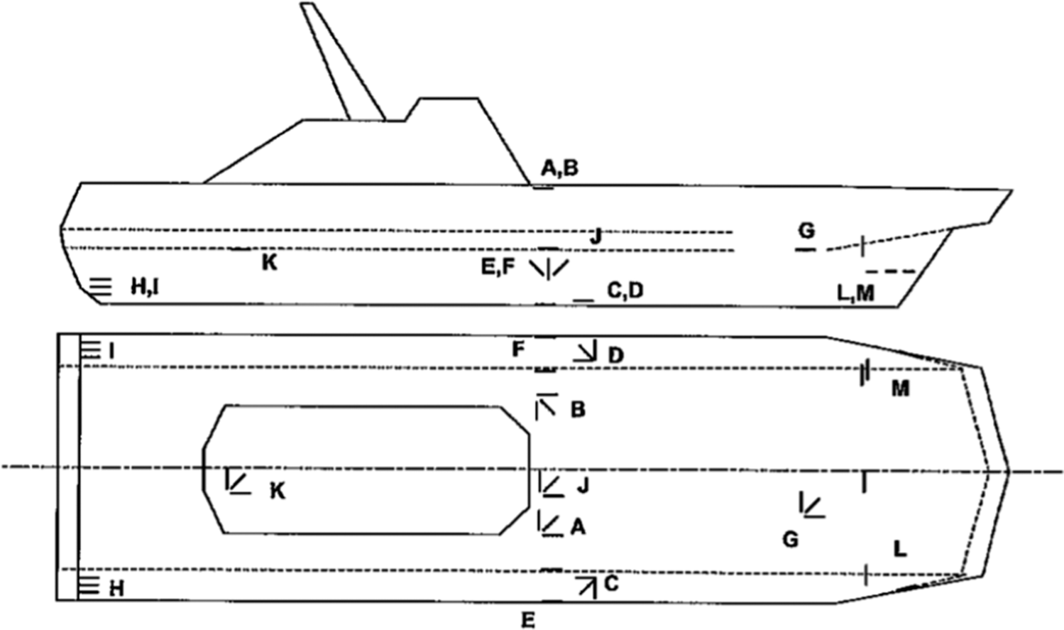
Midships cross-section of Skjold, with sensor placement (Wang et al., Reference Wang, Pran, Sagvolden, Havsgård, Jensen, Johnson and Vohra2001).
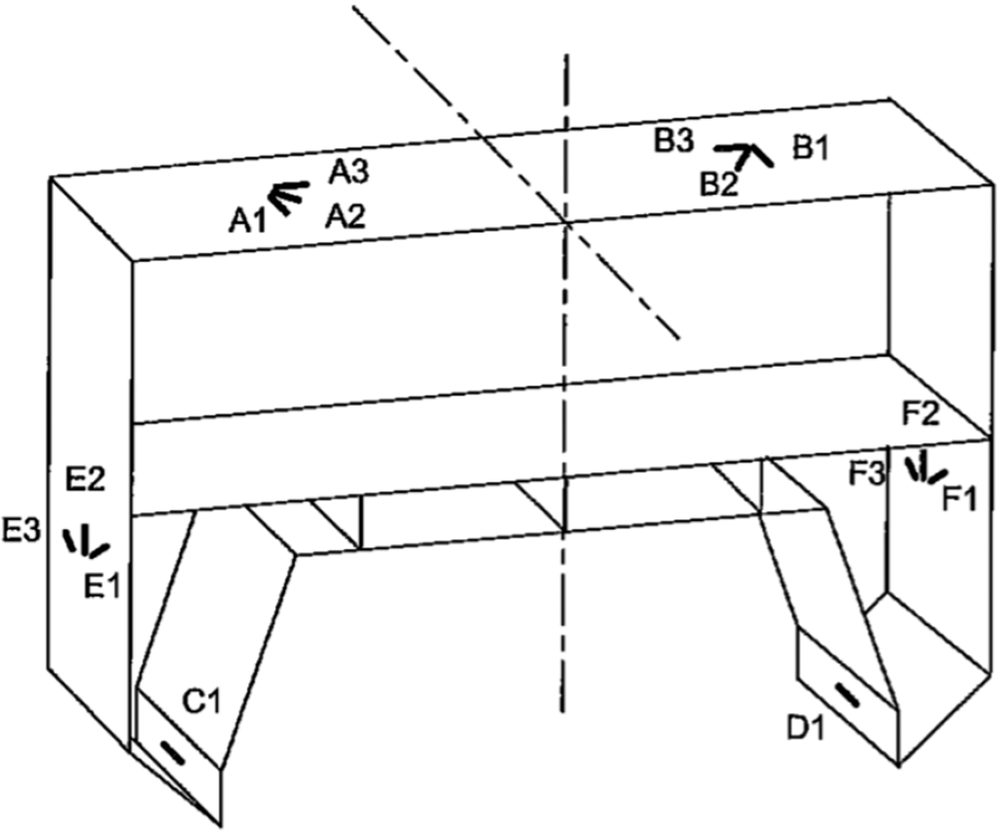
The system was further developed for the Alta/Øksøy class of mine countermeasure vessels with a view to providing risk-based operator guidance and CBM tools. Using load distributions and the recent load spectrum, the operator was provided guidance on the current overloading risk with alarm and warning levels set by the ship owner’s policy. In addition, a data-driven tool based on vessel motions and fleet history provided additional guidance parameters. The onshore CBM tool focused on providing information on load histories and local/global overloading events, which helped guide the inspection of the sandwich hull. A prototype of the system was installed in 2008 and has been in operation on the series since 2013.
9.2. United States Coast Guard
The United States Coast Guard (USCG) has adopted a fleet-wide CM program for the 154 ft Sentinel-class fast response cutters, using a system consisting of three unidirectional strain gauges and two to three multi-directional gauges (rosettes). The systems are in operation on all 50 vessels in active service, providing information on fatigue development and load spectra in the form of an automatically generated weekly data transfer, containing a pdf report as well as summary data files.
Other monitoring campaigns have been done on the USCG vessels based on their “Fatigue Life Assessment Program” (Stambaugh et al., Reference Stambaugh, Drummen, Cleary, Sheinberg and Kaminski2014). As part of the project, a hull structure monitoring system was installed on board two USCG National Security Cutters (NSC) (Drummen et al., Reference Drummen, Schiere, Dallinga, Thornhill and Stambaugh2014; Hageman et al., Reference Hageman, Drummen, Stambaugh, Dupau, Herel, Derbanne, Schiere, Shin and Kim2014; Stambaugh et al., Reference Stambaugh, Drummen, Cleary, Sheinberg and Kaminski2014; Drummen et al., Reference Drummen, Rogers, Benhamou, Hageman and Stambaugh2019). The system was designed as the minimum system to quantify fatigue life and extreme loads of the hull structure of this class and support long-term structural maintenance decisions. The instrumentation consisted of three LBSGs, three unidirectional strain gauges, one MRU, and one DGPS. Measurements from the three LBSGs were used to infer the vertical and horizontal bending moments. The overall position of the LBSGs and local strain gauges is presented in Figure 3. The number and positions of LBSGs were optimised using hydro-structural software.
Locations of the strain gauges on NSC (Drummen et al., Reference Drummen, Rogers, Benhamou, Hageman and Stambaugh2019).
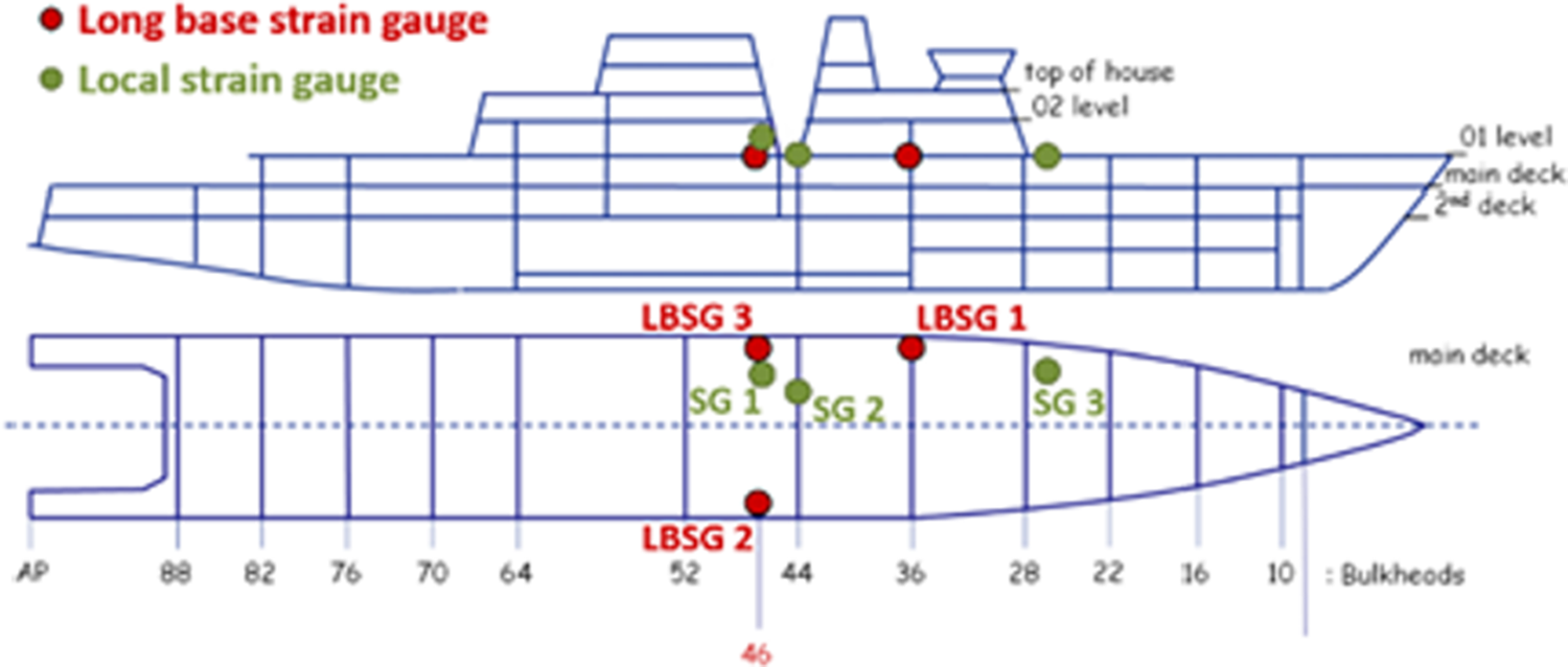
9.3. Sealift service containership equivalent
Naval sealift services, although not at the forefront of warfare operations, are of vital importance to their support. Vessels dedicated to this mission are varied in types, sizes, and functions; many navies use civil merchant fleet services alongside their own sealift fleet for cost-optimised operations when risk of attack is not an issue. Large ships (200–300 m in length) such as dry cargo, tankers, and containerships work in the sealift fleet to perform prepositioning and seabasing. A notable example of this is the vessel MV Maj. Bernard F. Fisher (T-AK-4396), a containership operated by the U.S. Military Sealift Command. Equivalently, the authors had access to a CM campaign of a 260 m ship of the same type (and therefore with similar structural design and behaviour): the ZIM Luanda containership.
In the Research & Development project FIBRESHIP (Fibreship, 2019), the structural health of the ZIM Luanda containership was monitored in the navigation route from Valencia, Spain to Halifax, Canada (about 3300 nm). The sensor network was composed of an environmental tracker, inclinometers, strain gauges, and an IMU, as shown in Figure 4. The data provided by the sensors were recorded and processed by a DAcS. The main objective was to constantly track the structural integrity of the ship in real time, guaranteeing efficiency and safety throughout the transatlantic voyage. It is important for any CM system to target the critical properties of the ship structure to provide meaningful results to downstream consumers, such as CBM policies or procedures. For this vessel, due to its length, the CM system targeted structural deformation (torsional and bending moments) to assess integrity and structural failures. The results were correlated to sea state and simultaneously measured weather conditions (via GPS location and hindcast) to validate the hydro-structural numerical model developed in the project. The sensors in this monitoring campaign included:
-
• Environmental tracking system: This system combines data from the Airmar 220WX WeatherStation (220WX weatherstation® instrument, 2025) (wind speed, wind direction, vessel location) with wave information obtained via hindcast at specific GPS points. Note that if radar is available, this system directly receives and processes the data in real-time; otherwise, the system uses GPS to retrieve sea state information from public databases and then merges all the data together. It provided sea waves’ direction, height and periods, and wind direction and speed.
-
• Biaxial inclinometers: Five sensors distributed along the ZIM Luanda ship were installed. These sensors provided real-time information on the ship’s rotational movements in the X and Y axes which were fundamental for assessing the hull’s hogging, sagging, and torsional deformations.
-
• Strain gauges: Installed at the mid-section, where bending stresses were presumed to be highest, these gauges measured the local deformations, using a targeted configuration to focus on axial deformations.
-
• Relative displacement sensors: Here, eddy current displacement sensors (TQ-402) (Data sheet, 2025) measured strain by correlating hull displacement with changes in the magnetic field. These sensors were tested as an alternative method of capturing local deformations, correlating them with strain gauge data, thus ensuring the reliability of the monitoring system. The sensors were mounted facing the hull on a rod, maintaining a small gap to detect any hull movement at the sensor tip through changes in the magnetic field.
-
• Inertial measurement unit: With its six degrees of freedom, the IMU captured the vessel’s motions (roll, pitch, yaw, surge, sway, and heave) and essential data for correlating the external loads (environmental factors) with the ship’s structural responses.
Description for sensor positioning in ZIM Luanda Containership (Fibreship, 2019; Fuentes, Reference Fuentes2019).
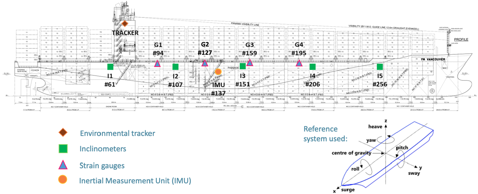
The monitoring results were able to provide the hogging, sagging, bending, and torsional deformations of the containership at different operational and weather conditions, showing that they were well below the safety limits recommended by classification societies for regular sailing conditions, though they also showed that in case of extremely rough navigation conditions the bending moments could reach some values above allowable limits. Outputs from a CM system like the one deployed here could also be used for assessing ship-wide and local structural health indicators and fatigue in the long term.
9.4. Lessons learned from monitoring campaigns
All three monitoring campaigns presented above offer valuable lessons learned for implementing structural CBM onboard naval vessels. The monitoring campaign from the Royal Norwegian Navy indicated the potential in using FBG for real-time structural health monitoring (Wang et al., Reference Wang, Pran, Sagvolden, Havsgård, Jensen, Johnson and Vohra2001), as FBG can be a good choice for harsh or corrosive environments. For many sensors, a FBG system can be multiplexed, reducing the overall cost per sensor. By continuously analyzing the fiber strain signals, changes in the vessel stiffness can be analyzed, indicating the possibility for damage detection. The FBG system can also indicate static hull deformations, and with enough sensors, it can detect hull vibrations and monitor noise (i.e., the vessel acoustic signature). Using a modular design for the fiber optic sensing system was also indicated to be useful because then the modules can be adapted for different monitoring applications. Global forces were determined from some of the measured strains, allowing a clear comparison between the rule loads used in the vessel design and the experienced loads, giving a clear resulting safety factor. Such information can then be further used to optimise vessel weight and strength for future vessels of the same series (Pran et al., Reference Pran, Johnson, Jensen, Hegstad, Sagvolden, Farsund, Chang, Malsawma, Wang, Claus, William and Spillman2000).
Based on the USCG monitoring campaign, a minimum system to quantify fatigue and extreme loads and support long-term structural maintenance decisions was presented in Drummen et al. (Reference Drummen, Rogers, Benhamou, Hageman and Stambaugh2019). The instrumentation consisted of three LBSGs, two strain gauges, a MRU, and a GPS. The LBSGs were used to infer cross-sectional load effects like the vertical bending moment, as they cannot be measured directly. Measured strains were combined with the first few global vibration modes to obtain section loads (Schiere et al., Reference Schiere, Bosman, Derbanne, Stambaugh and Drummen2017). A similar approach was employed in Andoniu et al. (Reference Andoniu, De Lauzon and Lamaison2019) but used selected wave load cases instead of vibration modes; improved accuracy was achieved for the bending moments using this approach. The number of LBSGs to be used depends on the accuracy that is needed at a particular location on the ship. The system as described in Drummen et al. (Reference Drummen, Rogers, Benhamou, Hageman and Stambaugh2019) was not able to provide information about the actual cracks appearing on board; due to insulation and other internal structures on board, these might be difficult to detect. Therefore, an AE monitoring system was suggested to supplement the monitoring system. Strain gauge measurements from the early lifetime of the ship can then be used to pin-point a localized area in a later stage of the ship’s lifetime where fatigue cracks are expected. These insights form the major inspiration for the baseline sensor system suggested in Section 10.
From the ZIM Luanda campaign, it was found that it is crucial to incorporate the CM system during the vessel’s construction phase, akin to essential services like electrical and ventilation systems. This early integration can prevent the challenges faced with post-construction installation, such as adapting ship structure and routing system wires through complex ship sections, which proved to be a significant difficulty for the ZIM Luanda. The monitoring campaign findings further suggested that relative displacement sensors, despite their higher cost and potential installation challenges, offer advantages such as robustness, versatility, and ease of maintenance. They have been demonstrated to be as sensitive and accurate as traditional strain gauges. However, their cost and complexity of installation could limit widespread use. Additionally, the importance of sensor location was highlighted, with the mid-section being particularly crucial for measuring traction and compression deformations. The inability to use wireless sensor systems within steel ships due to the Faraday cage effect presented a substantial challenge, necessitating the use of specially designed cables that were immune to magnetic interference.
9.5. Other monitoring paradigms
Beyond the lessons learned from the specific monitoring campaigns discussed above, we can also look to other ship structure monitoring activities for inspiration. Virtual monitoring, beyond just for estimating the environmental conditions, offers some advantages: namely that the costs and effort involved in setting up and maintaining an analysis using hindcast are significantly lower than for a physically monitored system. But the accuracy of virtual monitoring is generally lower than that of a traditional monitoring system. DGPS data were utilized with wave hindcast to test a virtual monitoring approach in Thompson (Reference Thompson2020). This work found that the virtually calculated stress spectra were in good agreement with measured stress spectra from a naval vessel monitoring campaign. It was further found in Hageman and Thompson (Reference Hageman and Thompson2022) that physical monitoring resulted in more accurate fatigue estimates than virtual monitoring via wave hindcast, especially in storm conditions. While virtual monitoring does have its benefits, physical monitoring gives more accurate and reliable information for individual vessels. The field would benefit from further targeted research determining which quantities need to be physically sensed versus which can relatively reasonably be virtually sensed, and how this affects eventual prognostic assessments, to facilitate the uptake of CBM for naval vessels.
When a fleet of vessels is concerned, an efficient combination of physical and virtual monitoring can be done, as it is possible to physically monitor a single vessel within a fleet and extrapolate insights to other virtually monitored vessels within the fleet. Such fleet monitoring has already been implemented to improve wave environment estimations, based on combining information from multiple monitored vessels in a common area (Nielsen et al., Reference Nielsen, Brodtkorb and Sørensen2019; Mounet et al., Reference Mounet, Nielsen, Brodtkorb, Tannuri and de Mello2022, Reference Mounet, Chen, Nielsen, Brodtkorb, Pillai, Ashton and Steele2023). But of course, the variance of the operational area of the fleet is extremely important when deciding if fleet monitoring is possible. Using spectral fatigue analysis to compare the accumulated fatigue damage of 10 naval vessels within a fleet, Thompson (Reference Thompson2018) found significant influence of the operational area on the resulting damage. However, when considering a mini-fleet focused on a single area, the fatigue damage across vessels varied little. The implications of partial virtual monitoring of a fleet of vessels operating in different areas and prevailing environmental conditions were further explored by Hageman et al. (Reference Hageman, Drummen, Thompson and Stambaugh2022). In general, fleet monitoring, where at least some vessels are physically monitored, can be useful for the long-term decisions needed for fleet maintenance decisions but may be less useful for onboard reactions by crew for mission-readiness.
Monitoring campaigns can also be conducted just for short periods, theoretically under harsh conditions, to assess the current fatigue life of the vessel (Johnson et al., Reference Johnson, Lynch and Collette2018). However, it is important to note that the short-term monitoring needs to begin at or near the beginning of the vessel’s lifetime, unless there is also enough information about the past operational profile to correlate operational conditions with fatigue damage. It is also possible to combine virtual and physical monitoring by using a short-term perspective with a conversion matrix method (Thompson et al., Reference Thompson, Jiang and Benhamou2021). Related to the idea of short-term monitoring is that of linking monitored and unmonitored states. In this way, monitoring of the structural health in certain sea conditions has been used to infer the structural response in “unobserved states” using the power spectral density of measured structural health monitoring data (Mondoro et al., Reference Mondoro, Soliman and Frangopol2016; Zhu and Collette, Reference Zhu and Collette2017). Though such short-term monitoring can save costs, it is envisioned that life-long monitoring is more useful for tracking the vessel structural health and making informed decisions on maintenance.
Another notable monitoring approach is the “digital healthcare engineering” paradigm for marine assets (Sindi et al., Reference Sindi, Kim, Yang, Thomas and Paik2024; Kim et al., Reference Kim, Xie and Paik2025; Kim and Paik, Reference Kim and Paik2025) based on on-site monitoring, ship-to-shore data transmission, advanced analytics on a DT, AI-driven diagnostics, and predictive health analysis for maintenance planning. Developed for aging ships and offshore structures, this approach was particularly applied to an aging containership, and such a pipeline could also be interesting for naval vessels, especially the pillars of AI-driven diagnostics and predictive health analysis for maintenance planning. Some aspects might need to be adapted to address short-term decision making required for naval vessels, as digital healthcare engineering relies on high-fidelity simulations on detailed digital twins for diagnostics and prognostics. This high-fidelity digital twin and simulation module can be useful for long-term naval prognostics, where it has already been noted that simple models cannot accurately model longer-term damage growth.
10. Baseline naval condition monitoring sensor system for global integrity management
Back in Section 1, we defined two important questions which first needed to be answered to define a CBM system, and we offered possible answers from a naval perspective. Our desired outcome from implementing CBM is to support a naval vessel which can safely and effectively complete its mission, even with known structural issues. Crew onboard and support onshore should be able to operate the vessel with an understanding of the underlying structural risk. The CBM system should also be able to sense the initiation of important structural damage. To achieve these outcomes, the CBM system should globally identify and localize the beginnings of problem areas to be further investigated via more targeted monitoring or inspection. The system should further be able to indicate the risk level of those problem areas and estimate the probability that the damage will grow based on different operating scenarios. The CBM system should be able to give a general warning level to the crew about the structural integrity and more detailed descriptions to onshore support.
Based on the desired outcomes and the required outputs to achieve them, the described CBM components and the relevant literature, plus the vessel monitoring experience from the paper authors, we offer a resulting baseline global sensor system for naval structural CBM. This baseline system is defined by the minimum number of sensors for a global integrity management monitoring campaign of a general frigate, where the aim is to identify any global structural changes which have taken place to later follow-up with targeted monitoring or inspection. This baseline system should at least include the following:
-
• Wave inference system (IMU, virtual/ hindcast techniques, possibly with wave radar) to infer the wave excitation acting on the vessel in terms of spectral parameters (significant wave height, representative wave period, wave direction spectral shape). The IMU records the vessel motions and accelerations, also in connection with accelerometers (see below), with the intention to infer the wave excitation via the SAWB approach. This SAWB estimation of the wave excitation spectrum can be improved by hindcast data, supported by DGPS measurements (see below), and by the addition of a wave radar system, though this is an important cost-driver and can present other practical limitations for naval vessels. The sampling frequency for the IMU should be at least 20 Hz.
-
• Three LBSGs (two at midships, one at the forward quarter length) to infer the still water and vertical and horizontal bending moments of the vessel. A cost-accuracy analysis performed by Drummen et al. (Reference Drummen, Rogers, Benhamou, Hageman and Stambaugh2019) indicated that three LBSGs were enough to measure the vertical bending moment accurately with minimal effect on measuring the horizontal bending moment. These measured loads can be used to determine sectional loads and internal stresses using a conversion matrix method. The LBSGs provide information about the maximum global sectional load effects occurring on the ship. The loading that has been experienced can be obtained from a combination of wave information and operational information, as well as directly measured strains. With contextual information from the wave environment, the loading estimates can be compared to design expectations and limits. Combined with crack growth models, the measurements can be used to project crack growth and life expectancy.
-
• Eight accelerometers (four at port and four at the starboard side, both longitudinally distributed) to measure potential hull deformations and mode shapes/frequencies. These accelerometers will also provide information about the hull girder vibration levels and the shapes and frequencies of the lowest few global flexural vibration modes.
-
• Three to ten unidirectional strain gauges to quantify the level of the fatigue consumption at specific fatigue hotspots on the vessel, with one strain gauge per hotspot. A detailed hotspot analysis will reveal a number of critical hotspots in the ship’s structure. Only a limited number of these hotspots need to be monitored using unidirectional strain gauges, around 3–10. This number provides a good balance between the gathering of representative information regarding hotspot loading, as well as the costs and effort involved in installation and analysis of the data. The key point for selection of hotspots for monitoring is that different (combinations of) global loading mechanisms, such as vertical or horizontal bending at key sections, should dominate the loads at these hotspots.
-
• DGPS to keep track of the vessel speed and position, which in conjunction with the SAWB estimates from the vessel’s IMU, can inform hindcast models to better predict the encountered wave loading.
In general, the specific system design (i.e., exact sensor layout and location) will depend on analyzing the vessel (hydrodynamic and structural) model to identify optimal sensor locations. In addition, other types of naval vessels (aircraft carriers, offshore patrol vessels, mine warfare, etc.) will have other specific needs, calling for more detailed analyses and (likely) more sensors in important locations. The baseline system described here should be used to identify global structural changes to indicate closer monitoring campaigns at identified areas of interest. For example, this system might indicate specific regions where structural degradation is suspected, which could then be more closely monitored via AE or by visual inspection.
Additional sensing can also be added to expand capabilities beyond the asset integrity management approach examined here. For naval vessels, it will also be important to give tactical and survival advice by detecting impacts, updating damage stability, calculating residual hull girder strength, and offering possible advice on noise reduction measures, re-ballasting of tanks and compartments, and eventually abandoning ship, if needed. In highly dynamic regimes to offer information on battle readiness, sensors can be added to determine changes in weapon system accuracy due to hull girder deformations, hull girder and machinery vibration levels, and give possible advice on ship operations to aid in helicopter/other landing activities. For both of these expanded capabilities, more strain gauges, accelerometers, IMU/MRU, and flooding sensors would be needed.
A DT of the vessel can be created by combining numerical models with (real-time) measurement data and analytical techniques. This twin can be used to estimate the current state, with respect to fatigue accumulation, corrosion, etc., of selected representative points on the vessel. The number of points analyzed using a DT can be more extensive than the number that can be monitored directly, thereby increasing the impact of the monitoring system. The use of the monitoring data and the DT fidelity depends on the decision timeline. For short-term decisions, these sensed data should feed into relatively simple physical models, which can give reasonable damage evolution estimates in the short term. This allows the crew to make risk-informed decisions to determine, for example, if a mission can continue with the ship in its current structural state. This overall framework then involves a relatively simple DT of the ship based on simple physical models which can be evaluated in real-time. For the longer-term decisions, these monitored data should feed into more detailed physical models which can be updated over time with the structural condition to give a better long-term prognosis and link to long-term vessel and fleet maintenance planning. These sensed data can then be transferred onshore when a ship is back at base to update the lifecycle planning.
In order to provide advice to the maintenance personnel for both onboard and onshore decisions not only must the current state of the structure be known but also acceptable degradation thresholds must be defined. If one such threshold is reached for one of the representative points in the DT, further action is required. Such advice should also include statements on the risk that the threshold will be exceeded in the upcoming deployment. Therefore, the DT should be connected to scenario simulations that are able to incorporate the relevant variations in loading. In that case, the risk of exceeding these thresholds in the upcoming deployment can be estimated, potentially incorporating different modes of operation. The operator can then make an informed decision on how to execute the mission. Optionally, during the deployment, these risks can actively be monitored by the maintenance personnel using information obtained from the measurement system and DT.
11. Conclusions and calls for future research directions
This paper presented an end-to-end view on structural CBM for naval vessels, beginning with the overarching motivations for implementing such a system onboard. Different maintenance strategies were defined, and out of all maintenance strategies, CBM was indicated as the preferred option for naval vessels based on the special operating conditions of naval vessels stemming from their mission-centric usage. The authors’ motivation for naval CBM is to support naval vessels in safely completing their mission, even with structural damage, and to give crew members an informed view of the structural risk. The desired CBM system should then locally sense and analyze data to give short-term guidance on areas of concern to be further monitored and inspected. Longer duration sensing data can then be used onshore in more detailed physical models for long-term prognosis and fleet-wide decision making. Based on this over-arching naval structural CBM motivation, the major components of a CBM system were outlined with specific focus on damage due to fatigue, corrosion, and extreme loading. To monitor the vessel structural health and make informed maintenance decisions, a digital framework incorporating sensing technology, a data acquisition system, data analysis software, and a digital twin is needed. Within these components, diagnostic and prognostic analyses can then support informed decision making. Special focus in the discussion was given to monitoring the environmental conditions faced by the vessel along with the resulting damage due to fatigue, corrosion, and extreme loading. Here, different sensing choices and paradigms were further discussed in light of the foundational and state-of-the-art literature.
In general, condition monitoring is well-established, though not yet for targeted corrosion, crack, and coating in-service monitoring, where more focused strategies are needed and research is still on-going. For fatigue and corrosion monitoring, AE and the combination of AE and EN, respectively, are noted as particularly promising solutions. More research needs to focus on the localization and characterisation of damage, as well as quantifying how robust and dependable these estimates are as distance between the sensor and damage location grows. Research to extend the reach of AE and EN technologies to in-situ ship monitoring, also taking into account complex ship structure geometries, will significantly increase the reliability and impact of sensing-informed structural CBM. There are also big advances being made in monitoring corrosion coating quality which can be very valuable for asset protection. However, on-line coating monitoring using EIS and its implementation into a CBM strategy is still in the beginning stages and needs to be further researched in order to make its diagnosis reliable and its real-world implementation practical.
Further research to accelerate the uptake of structural CBM should incorporate prognostic and health management paradigms to leverage sensed data with physics-based models for a better view of system integrity. ML and AI are emerging as powerful tools to analyze the large amounts of sensed data, detect/characterise damage conditions, and eventually make maintenance decisions. Research focusing on improving hybrid physics-based ML/AI models can further improve the diagnosis of damage, and more work should focus on expanding the ML approaches noted in this paper to more complicated ship structure geometries. In general, ML can also be helpful in optimising maintenance decisions based on condition monitoring and should be further studied to make CBM implementation feasible. And as noted by Kamariotis et al. (Reference Kamariotis, Chatzi, Straub, Dervilis, Goebel, Hughes, Lombaert, Papadimitriou, Papakonstantinou, Pozzi, Todd and Worden2024), more research needs to be done integrating CM into decision making processes to encourage stakeholders to accept and implement CM, especially for complex systems like naval vessels.
Three previous monitoring campaigns undertaken by the paper authors for different vessel types were discussed along with lessons learned. Based on this past experience, a baseline minimum sensor system to monitor damage due to fatigue, corrosion, and extreme loading on a naval frigate was defined. This system is purely meant for asset integrity management and is made up of a wave inference system (combination of IMU and virtual/hindcast techniques, plus possibly a wave radar), 3 LBSGs, 8 accelerometers, 3–10 unidirectional strain gauges to monitor hotspots, and a DGPS. It is acknowledged that more sensors would be needed to give tactical and survival advice, plus information on battle readiness. But in general, it is the authors’ belief that the baseline sensor system presented here can reliably track the global vessel structural health and indicate areas which need to be more closely monitored or inspected, specifically by AE. This already would be a valuable addition to navy vessels to better monitor their lifetime structural health, optimise maintenance decisions, and improve safety and risk awareness during important missions or extended deployments.
Other monitoring paradigms were also discussed, such as virtual, fleet, and short-term solutions. Physical monitoring will have the best accuracy for individual ships, but combinations with virtual assessment and expanding physically monitored knowledge across fleets can be certainly useful and potentially offer the best value for fleet assessment. Another useful area of future research would be on improving the connection between physically and virtually monitored ships within a single fleet. Some physical monitoring will be needed, if only to give better estimates of naval vessel fatigue limit states, but we have already seen that a relatively simple baseline sensor system as described above can give reasonably accurate results for both short-term and long-term CBM. When linked with a decision framework to optimise decisions, such a monitoring system can be used to make better present and future choices about vessel maintenance and usage, and structural naval CBM can be achieved.
Abbreviations
- AE
-
acoustic emission
- AI
-
artificial intelligence
- AIM
-
asset integrity management
- CBM
-
condition-based maintenance
- CM
-
condition monitoring
- DAcS
-
data acquisition system
- DAnS
-
data analysis system
- DBN
-
dynamic Bayesian network
- DT
-
digital twin
- EIS
-
electrochemical impedance spectroscopy
- EN
-
electrochemical noise
- FBG
-
fiber Bragg grating
- (i)FEM
-
(inverse) finite element model
- (D)GPS
-
(Differential) Global Positioning System
- IMU
-
inertial measurement unit
- LBSG
-
long-base strain gauge
- MIMOSA
-
Machinery Information Management Open System Alliance
- ML
-
machine learning
- MoD
-
Ministry of Defense
- MRU
-
motion reference unit
- NDT
-
non-destructive testing
- NSC
-
National Security Cutter
- OMA
-
Operational Modal Analysis
- OSA-CBM
-
Open System Architecture for Condition-Based Maintenance
- SAWB
-
ship as a wave buoy
- US
-
ultrasound
- USCG
-
United States Coast Guard
Data availability statement
No data were used in this work.
Acknowledgments
The authors would like to thank the anonymous reviewers whose detailed, thorough, and thoughtful comments led to a substantially improved review.
Author contribution
Conceptualization, writing—review and editing: H.S., I.D., R.H., A.H., S.M.R., T.T., G.S., I.Z.; Writing original draft: H.S. All authors approved the final submitted draft.
Funding statement
This research was supported by the European Defence Fund under grant agreement 101103257—dTHOR EDF-2021-NAVAL-R-2. Open access funding provided by Delft University of Technology.
Competing interests
The authors declare no competing interests.
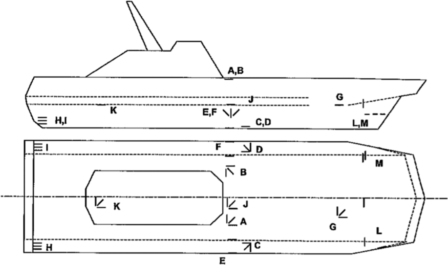
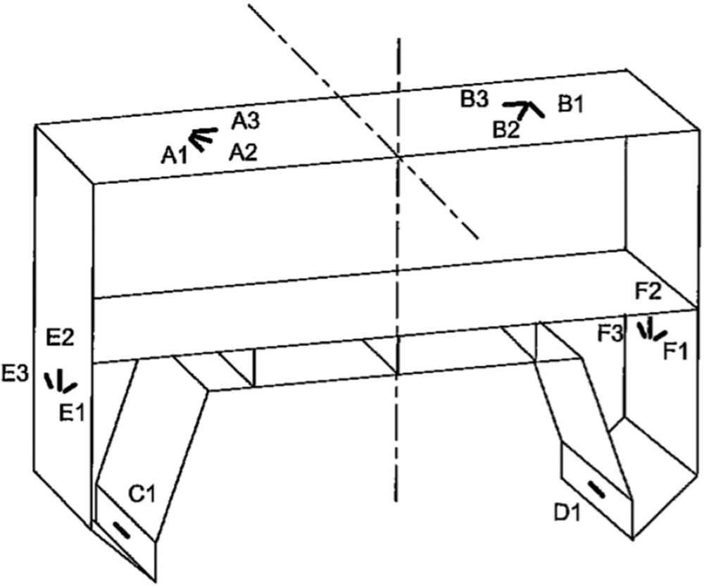


 Open access


Comments
No Comments have been published for this article.