Introduction
Solid-oxide fuel cells (SOFCs) are the most efficient energy conversion devices to directly convert stored chemical fuel energy to electricity via electrochemical reactions (see the Introductory article in this issue).Reference Wachsman and Lee1,Reference Steele and Heinzel2 They are uniquely capable of operating with a wide range of energy resources, from current conventional fuels (e.g., diesel, natural gas, and gasoline) to biofuels (e.g., ethanol, biodiesel, and biogas), as well as hydrogen, with low environmental impact due to their high efficiency.Reference Murray, Tsai and Barnett3–Reference Song8
Unfortunately, current SOFCs must operate at high temperatures ≥800°C to obtain desirable high electrolyte oxygen ion conductivity and high electrode oxygen reduction/fuel oxidation reaction rates due to the thermally activated nature of these processes, resulting in high system costs, slow start-up, and high degradation rates.
A reduction in SOFC operating temperatures below 700°C allows for the use of inexpensive stainless steel for bipolar plates (which provide the series electrical connection between cells and the gas channels for fuel at the anode and oxidant at the cathode) and balance-of-plant, commercial high-temperature gaskets instead of rigid glass/ceramic-based sealants (to prevent gas leakage between individual cells in a stack),Reference Wachsman and Lee1,Reference Lee, Yoon and Wachsman9–Reference Brett, Atkinson, Brandon and Skinner11 as well as reducing thermally activated material degradation rates. Therefore, development of high power density SOFCs operating at reduced temperatures would be a crucial breakthrough.
In this regard, nanostructural approaches to improving SOFC performance have drawn the attention of researchers in recent years due to the tremendously increased electrode-specific surface area and potential for enhanced properties in nanostructured materials.Reference Arico, Bruce, Scrosati, Tarascon and Van Schalkwijk12 Synergistically, nanostructures enable lower operating temperatures, while reduced operating temperatures make three-dimensional (3D) nanostructures more stable against coarsening, which is one of the major performance degradation mechanisms in SOFC electrodes.
In this article, we review the development of a variety of nanostructured electrodes and electrolytes and discuss their roles in enhancing SOFC performance at reduced temperatures.
Nanostructured cathodes
Enhancing oxygen reduction reaction at reduced temperature
It is well known that at reduced temperatures, activation polarization (the voltage drop due to the reaction kinetics of cathode oxygen reduction and anode fuel oxidation) at SOFC electrodes dominates performance losses. Among these, the oxygen reduction reaction (ORR) at the cathode is a thermally activated process with high activation energy and sluggish reaction kinetics.Reference Adler13–Reference Ishihara, Kudo, Matsuda and Takita16 On the other hand, the hydrogen oxidation process at the anode, such as dissociated chemisorption of hydrogen, has been known for much faster kinetics with less temperature dependence.Reference Mogensen and Skaarup17,Reference Godickemeier, Sasaki, Gauckler and Riess18 Thus, at reduced temperatures, the activation polarization loss is ascribed mainly to the ORR at the cathode.
At high temperatures, La1–xSrxMnO3–δ (LSM)-based materials have been the most popular choice due to their reasonable electrochemical performance as well as high chemical and thermal compatibility with the conventional yttria-stabilized zirconia (YSZ) electrolyte.Reference Minh19–Reference Jiang22 However, at reduced temperatures, their negligible ionic conductivity and low oxygen surface exchange restrict the electrochemically active reaction sites (triple-phase boundaries [TPBs] where ionic and electronic conducting phases and the gas phase meet) to the cathode/electrolyte interface, thus significantly increasing the activation polarization loss.Reference Brandon, Skinner and Steele23 Enhancement of the LSM-based cathode performance at lower temperatures has been achieved by a composite cathode approach in which LSM as an electron-conducting phase is mixed with an electrolyte material as an ionic conducting phase to expand TPBs into the cathode bulk.Reference Tanner, Fung and Virkar24–Reference Lee, Jung, Yoon, Lidie, Camaratta and Wachsman26
As an alternative strategy, new cathode materials with higher oxygen reduction catalytic activity and oxygen transport properties at reduced temperatures have been explored. For example, various cobaltite-based perovskite cathodes, including La1–xSrxCoO3–δ (LSC), La1–xSrxCo1–yFeyO3–δ (LSCF), Sm1–xSrxCoO3–δ (SSC), and Ba1–xSrxCo1–yFeyO3–δ (BSCF), have been intensively studied due to their mixed ionic and electronic conduction (MIEC) as well as an inherent higher catalytic activity of oxygen reduction at temperatures below 700°C.Reference Xia, Rauch, Chen and Liu14,Reference Deganello, Esposito, Miyayama and Traversa27–Reference Shao and Haile29 With this MIEC character, the TPB region is effectively expanded across the entire cathode surface. However, for practical use, cobaltite-based cathodes encounter issues of reactivity with the prevailing zirconia-based electrolytes,Reference Petric, Huang and Tietz30,Reference Mai, Becker, Assenmacher, Tietz, Hathiramani, Ivers-Tiffee, Stover and Mader31 relatively high thermal expansion coefficient, as well as long-term stability issues related to Sr segregation and CO2 poisoning.Reference Bucher, Egger, Caraman and Sitte32,Reference Oh, Gostovic and Wachsman33
Besides intrinsic material properties, microstructural tailoring down to the nanoscale is an important focus to enhance cathode performance at reduced temperature. Transferring the effective feature size of the catalytic phase from the micro (10–6) to the nano (10–9) scale allows an increase in the electrochemical reaction sites (TPBs) by a factor of 109 [(10–6/10–9)3] due to the extremely high specific surface area, thus potentially compensating the exponential decrease in ORR rates (activation polarization) at the cathode as temperature decreases. Several model calculations support the theory that particle size reduction significantly increases the TPB length in composite cathodes.Reference Chen, Chan and Khor34–Reference Zhu, Ding and Xia36 In addition, since nanostructures increase the surface to volume ratio, catalytic activity can be enhanced due to increased surface vacancy concentration.Reference Arico, Bruce, Scrosati, Tarascon and Van Schalkwijk12
Synthesis of nanostructured LT-SOFC cathodes
Ultrafine initial powders enable the establishment of nanostructured cathodes using conventional ceramic powder processing. There have been numerous studies on nano-powders (or nanoparticles) synthesized by various wet chemical methods, including citrate-nitrate combustion,Reference Deganello, Esposito, Miyayama and Traversa27 glycine-nitrate combustion,Reference Chick, Pederson, Maupin, Bates, Thomas and Exarhos37–Reference Lee, Lee, Camaratta and Wachsman39 sol-gel,Reference Yoon, Han, Nam, Lim, Oh, Hong, Yoo and Lim21,Reference Jang, Hyun and Kim40,Reference Zhen and Jiang41 co-precipitation,Reference Sato, Kinoshita, Abe and Naito42–Reference Lee, Lidie, Jeon, Hitz, Song and Wachsman45 and spray-pyrolysisReference Hagiwara, Hobara, Takizawa, Sato, Abe and Naito46 for low temperature (LT) -SOFC cathode applications.
For example, nanostructured LSCF and Sm-doped ceria (SDC) powders reported by Deganello et al. were prepared by citrate-nitrate auto-combustion synthesis.Reference Deganello, Esposito, Miyayama and Traversa27 Using this method, the authors obtained perovskite phases at temperatures as low as 600°C. After sintering, the LSCF cathode showed uniform morphology with an open (porous) network of well-connected particles, of which the feature size was ∼200 nm, resulting in an area-specific resistance (ASR) of 0.13 Ω cm2 at 700°C.
Recently, nanoscale pyrochlore bismuth ruthenate (Bi2R2O7, BRO7) with ∼30 nm crystallite size was prepared via glycine-nitrate combustion.Reference Lee, Lee, Camaratta and Wachsman39 Using this nano-BRO7, the BRO7-ESB nanocomposite cathode exhibited ∼9 times lower SOFC cathode ASR at a reduced temperature (500–700°C) compared to that fabricated with micron-sized features (e.g., 0.22 versus 2.00 Ω cm2 at 600°C).
Sato et al. utilized in situ co-precipitation to fabricate LSM-YSZ nanocomposite particles using nano-sized YSZ (∼3 nm) as seed crystals.Reference Sato, Kinoshita, Abe and Naito42 The final cathode had a uniform porous structure with feature size of ∼100 nm and yielded an ASR of 2.82 Ω cm2 at 650°C. In addition, Lee et al. reported nano-scale 20 mol% erbia-stabilized bismuth oxides ((Er2O3)0.2(Bi2O3)0.8, ESBs) with a crystallite size of 20 nm using a reverse strike co-precipitation method.Reference Lee, Lidie, Jeon, Hitz, Song and Wachsman45 Due to the high specific surface area, the obtained nano-sized ESB allowed for a significant reduction in SOFC processing temperature and time without sacrificing ionic conductivity, as well as enhanced ORR rates in a nanocomposite cathode; showing ∼35% lower ASR (e.g., 0.20 Ω cm2 at 600°C) compared to that of the conventional cathode (e.g., 0.43 Ω cm2 at 600°C).
Baqué et al. developed nano-sized LSCF oxides of ∼150 nm particle size and ∼30 nm crystallite size using unique chemical solution routes with acetic acid and hexamethylenetetramine. A nanostructured LSCF prepared with the nanoparticles exhibited impressively low ASRs (e.g., 0.4 Ω cm2 at 450°C).Reference Baque, Caneiro, Moreno and Serquis47
However, “building nanostructures” with ultrafine particles usually requires high-temperature sintering to provide sufficient connections (necking) between particles for mechanical strength in 3D porous cathode structures. The nanoparticles are susceptible to coarsening or agglomeration during this process due to their high surface energy, thus easily losing their benefits of high surface area. Moreover, feature size reduction must be done while maintaining high percolation of ionic, electronic, and gas phase conduction to minimize the cathode’s ohmic and concentration polarizations, respectively.
Recently, infiltration or impregnation methods have drawn attention as an approach to construct nanostructured electrodes while avoiding the previous issues.Reference Jiang48–Reference Jiang51 In these techniques, a simple solution of nanoparticle precursors (e.g., metal nitrate solutions) are deposited into pre-sintered (e.g., ∼1400°C) rigid porous electrolyte or electrode scaffolds. Subsequent nanoparticle formation is enabled by calcining at much lower temperatures (≤800°C), preserving nanoscale features in the final cathode structures.
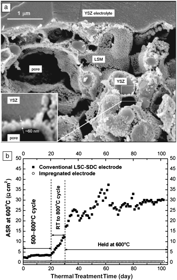
Sholklapper et al. reported a single-step infiltration method to incorporate LSM into a pre-sintered YSZ network, resulting in well-distributed nano-sized (30–100 nm) LSM particles on YSZ scaffold surfaces (Figure 1a).Reference Sholklapper, Lu, Jacobson, Visco and De Jonghe52,Reference Sholklapper, Kurokawa, Jacobson, Visco and De Jonghe53 Later, Zhao et al. developed a nanostructured cathode based on LSC at lower temperatures.Reference Zhao, Peng and Xia54 LSC was impregnated into a porous SDC scaffold, resulting in enhanced electrochemical performance compared to that of the conventional composite cathode. Moreover, no measureable degradation in ASR was observed even after 20 thermal cycles at 500–800°C and 10 cycles at room temperature to 800°C with the nanostructured LSC-SDC cathode, demonstrating high stability upon thermal cycling despite the significant difference in thermal expansion between LSC and SDC (Figure 1b).
(a) A representative microstructure of a nanostructured cathode obtained via an infiltration process. This cross-sectional scanning electron microscope image shows well-distributed ∼60-nm-sized LSM nanoparticles on porous yttria-stabilized zirconia (YSZ) scaffolds after infiltration and sintering. (b) This plot shows area-specific resistance (ASR) at 600°C for the infiltrated (impregnated) cathode and the conventional La1–xSrxCoO3–δ-Sm-doped ceria (LSC-SDC) cathode upon thermal treatment for 100 h, demonstrating long-term stability of the nanostructured cathode consisting of a SDC backbone with infiltrated LSC nanoparticles. RT, room temperature. (a) Reprinted with permission from Reference 52. © 2006 The Electrochemical Society. (b) Reprinted with permission from Reference 54. © 2008 Elsevier.

An efficient nanostructured cathode architecture was obtained using a thin layer LSM-coated LSCF cathode.Reference Lynch, Yang, Qin, Choi, Liu, Blinn and Liu55 In this design, the electrochemical activity of the cathode was enhanced due to the promotion of oxygen adsorption and dissociation (which is a rate-limiting step in ORR of LSCF)Reference Kan, Kan, Van Assche, Armstrong and Wachsman56–Reference Armstrong, Duncan and Wachsman59 by the LSM layer, as well as increased oxygen vacancy formation in the thin LSM surface layer. The authors attributed the enhanced long-term stability of the nanostructured cathode to the formation of a hybrid interfacial phase between LSM and LSCF.
Zhi et al. reported that a 3D nanofiber network cathode consisting of electrospun nanofiber YSZ scaffolds and LSM nanoparticles deposited by infiltration effectively decreased cathodic polarization by 70% to 90% compared with a conventionally mixed LSM-YSZ cathode,Reference Zhi, Mariani, Gemmen, Gerdes and Wu60 demonstrating the great potential of one-dimensional (1D) nanostructures for high-performance LT-SOFCs.Reference Zhi, Lee, Miller, Menzler and Wu61–Reference Bellino, Sacanell, Lamas, Leyva and Walsoe de Reca64
The stability of a highly active LSC infiltrated cathode was promoted by a conformal layer of nanoscale ZrO2 film on the surface of LSC nanoparticles supported on La0.8Sr0.2Ga0.83Mg0.17O3–δ (LSGM) through atomic layer deposition (ALD), as shown in Figure 2a.Reference Gong, Palacio, Song, Patel, Liang, Zhao, Goodenough and Huang65 The ALD-ZrO2 overcoats reduced cathodic ASR by a factor of ∼19 and suppressed the time-dependent degradation up to 4000 hours, probably by prevention of LSC nanoparticle growth and of Sr segregation to the LSC surface (Figure 2b–c).
(a) Transmission electron microscope diffraction contrast image showing nanoscale atomic layer deposition (ALD) ZrO2 overcoats (30 ALD cycles) on LSC nanoparticles. (b) Comparison of long-term stability of pristine and ALD-ZrO2 overcoated nanostructured LSC cathodes over 4000 h. (c) Schematic showing the multifunctionality of gas transport, mixed conductivity, confinement of nanoparticles, and suppression of Sr-segregation presented by the nanoscale ZrO2 overcoated on the surface of a nanostructured LSC cathode. Sr'La is a point defect created by substituting La with Sr, while ZrCo˙ is a point defect created by substituting Co with Zr in LSC, and Co'Zr is a point defect created by substituting Zr with Co in ZrO2. Vo¨ , Oox, and h˙ represent an oxygen vacancy, a regular oxygen in a crystalline lattice, and an electron defect (hole), respectively. Reprinted with permission from Reference 65. © 2013 American Chemical Society.
Nanostructured anodes
Promoting hydrocarbon oxidation at reduced temperature
SOFCs are uniquely capable of converting most types of hydrocarbon-based fuels, from conventional fossil fuels to biomass and potentially municipal solid waste, to electricity with high efficiency due to their ability to internally reform hydrocarbons into hydrogen and carbon monoxide at high operational temperatures, ≥700°C.Reference Wachsman and Lee1,Reference Song8 This advantage of fuel flexibility allows SOFCs to be operated on the existing fuel infrastructure, which is important for “current market” penetration.Reference Wachsman, Marlowe and Lee10 However, as operational temperature decreases, the conventional Ni-YSZ cermet anodes have experienced power output degradation under hydrocarbon conditions due to carbon formation (coking) and sulfur poisoning, as well as Ni oxidation to NiO during thermal cycling.Reference Sun and Stimming66–Reference Eguchi, Kojo, Takeguchi, Kikuchi and Sasaki68
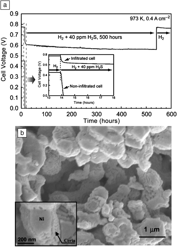
CeO2-based anodes have been demonstrated to improve both coking and sulfur poisoning resistance, as well as the ability for reported “direct hydrocarbon oxidation.” Murray et al. pioneered direct electrochemical utilization of methane in SOFCs at low temperatures using ceria-containing anodes.Reference Murray, Tsai and Barnett3 They employed a nanostructured yttria-doped ceria (YDC) layer (500 nm) on a 2-μm-thick Ni-YSZ anode by sputtering, resulting in a 370 mW cm–2 power density for methane at 650°C. Later, Kurokawa et al. reported high sulfur tolerance for Ni-YSZ anodes infiltrated with ceria nanoparticles.Reference Kurokawa, Sholklapper, Jacobson, De Jonghe and Visco69 A SOFC with the nanoparticle coated anode was operated with moderate power density on humidified H2 fuel containing 40 ppm H2S at 700°C for 500 h, while the power density of a SOFC without the ceria nanocoating dropped to near zero (Figure 3).
Demonstration of the effect of infiltrated ceria nanoparticles on enhancing sulfur tolerance of the Ni-YSZ anode. (a) Solid-oxide fuel cells (SOFCs) voltage as a function of time for cells exposed to 40 ppm H2S at 700°C for 500 h. The inset shows a magnified plot of the dotted region, clearly showing that the cell voltage (thus, the power density) of a SOFC without a ceria nanocoating dropped to near zero in ∼14 h primarily due to sulfur poisoning of the Ni surface. (b) Scanning electron micrographs of a ceria infiltrated cathode supported cell after exposure to 40 ppm H2S for 500 h. Reprinted with permission from Reference 69. © 2007 The Electrochemical Society.
Another approach is to use alternative metal catalysts to Ni, which is known to be susceptible to sulfur poisoning and coking. Park et al. reported that Cu-CeO2 (or SDC)-YSZ composite anodes significantly suppressed the carbon formation on the anode surface.Reference Park, Vohs and Gorte4 However, it is difficult to make composite electrodes due to the difference in sintering temperatures between Cu (<900°C) and YSZ (>1400°C). Instead, Cu nanoparticles were deposited into a porous YSZ backbone by precursor solution infiltration.Reference Park, Gorte and Vohs70,Reference Gross, Vohs and Gorte71 The SOFC with this nanocomposite anode allowed direct utilization of hydrocarbon fuels, including methane, ethane, 1-butene, n-butane, and toluene. Moreover, high coking resistance and sulfur tolerance up to ∼400 ppm were exhibited without serious performance degradation. In this anode design, copper nanoparticles work mainly as an electronic conducting phase, and ceria (or SDC) nanoparticles promote hydrocarbon fuel reforming and oxidation as a catalyst.
All-ceramic anodes have also been explored as Ni-free alternative anodes, including perovskites La0.75Sr0.25Cr0.5Mn0.5O3,Reference Pena-Martinez, Marrero-Lopez, Ruiz-Morales, Savaniu, Nunez and Irvine72 La0.4Sr0.6Ti1–x, MnxO3,Reference Fu, Tietz and Stover73 Sr0.94Ti0.9Nb0.1O3,Reference Shen, Guo and Liu74 and double perovskite Sr2Mg1–xMnxMoO6–δ,Reference Huang, Dass, Xing and Goodenough5 as well as fluorite Ce0.6(Mn0.3Fe0.1)O2.Reference Ishihara, Shin, Vanalabhpatana, Yonemoto and Matsuka75 These have demonstrated high coking resistance and sulfur tolerance with hydrocarbon fuels. However, ceramic anodes require further improvement due to relatively low electrical conductivity and catalytic activity compared to Ni-based anodes.Reference Jiang, Chen, Chan, Kwok and Khor76,Reference Jiang, Liu, Ong, Wu, Li and Pu77 Recent studies showed that incorporating doped-ceria or Pd nanoparticles in the ceramic anodes effectively improved hydrogen/hydrocarbon oxidation.Reference Shin, Okamoto, Ida and Ishihara78–Reference Jiang, Ye, He and Ho81
Reducing activation polarization of anode supports
Thinner electrolytes minimize ohmic polarization losses, therefore, most contemporary SOFCs with a planar architecture have employed an anode-supported cell design to accommodate very thin electrolytes. In order to minimize concentration polarization, anode supports require a large pore microstructure for rapid gas transport, both to allow fuel in and reaction by-product (H2O and CO2) out.Reference Ahn, Yoon, Lee, Camaratta and Wachsman82 However, the highly porous anode structure compromises the number of TPBs and causes insufficient thermomechanical stability with poor interfacial contact between the anode and electrolyte.Reference Ai, Lu, Chen, Huang, Du and Su83 Moreover, the effective anode reaction zone with active TPBs is limited to within a 10-μm-thick interfacial region adjacent to the electrolyte.Reference Williford, Chick, Maupin, Simner and Stevenson84 Thus, tailoring of the interfacial microstructure with an anode functional layer (AFL) has been intensively explored.Reference Hassan, Menzler, Blass, Ali, Buchkremer and Stover85–Reference Lee, Yoon, Ahn and Wachsman89
For example, Lee et al. developed a nanostructured AFL by infiltrating a very small amount (2 wt%) of Ni and Gd-doped ceria (GDC) precursor solution into a pre-established submicron-sized AFL, resulting in a bi-modally integrated Ni-GDC network structure (Figure 4a–c).Reference Lee, Yoon, Ahn and Wachsman89 An anode-supported SOFC employing this AFL dramatically improved the peak power density by a factor of four compared to a SOFC without an AFL from ∼300 to ∼1160 mW cm–2 at 600°C due to increased TPB length as well as enhanced interfacial contact between anode and electrolyte (Figure 4d).
Nanostructured anode functional layers (AFLs). (a) Schematic illustration of the Ni-GDC anode/bimodal distribution (BI)-AFL/GDC electrolyte multilayer structure and (b) conceptual two-dimensional drawing of a BI-AFL structure showing the effect of BI-AFL on extending triple-phase boundary (TPB) length. Due to the superimposed Ni-GDC networks with two different particle sizes, a dramatic increase in TPB sites in three dimensions is expected. Yellow and red triangles represent TPBs in conventional AFL (C-AFL) and TPBs multiplied by BI-AFL, respectively. (c) A scanning electron microscope image of the BI-AFL surface shows the characteristic structure of nanoscale particle necking with submicron-sized particles. (d) Comparison of current–voltage (I–V) characteristics for solid-oxide fuel cells (SOFCs) with BI-AFL, C-AFL, and no AFL at 600°C, demonstrating significant improvement of SOFC performance with the new nanostructured (BI) AFL. Reprinted with permission from Reference 89. © 2012 Royal Society of Chemistry.
Adding highly active catalysts (e.g., Pd, Ru, doped-ceria) in the form of nanoparticles to Ni-based anodes is also beneficial for enhancing the anodic reaction.Reference Zhan and Barnett90–Reference Babaei, Jiang and Li92 Babaei et al. reported that Pd nanoparticles significantly enhanced the hydrogen oxidation reaction of Ni-GDC anodes.Reference Babaei, Jiang and Li92 The infiltrated nanoparticles reduced both electrode polarization and activation energy associated with low frequency impedance components, suggesting that Pd nanoparticles promoted the adsorption and diffusion processes of the H2 oxidation reaction on Ni-GDC anodes. Further, the authors observed evidence for the Pd/PdOx redox couple during H2 oxidation, and attributed the enhanced hydrogen adsorption and diffusion to spillover processes from the nano-sized Pd/PdO.
Nanoparticle deposition by infiltration effectively reduces the fabrication temperature, providing opportunities to combine higher performance materials that have suffered from undesirable interactions during conventional high-temperature sintering. For instance, Sr- and Mg-doped lanthanum gallate (LSGM) are good candidate electrolytes for reduced-temperature SOFCs due to high oxide ion conductivity (e.g., 0.015 S cm–1 at 600°C) and chemical stability over a wide range of partial pressures of oxygen.Reference Ishihara, Matsuda and Takita93,Reference Huang, Tichy and Goodenough94 However, interdiffusion with Ni during high-temperature sintering relegates LSGM to an “incompatible material” with Ni-based anodes. To overcome this issue, Zhan et al. recently developed high-performance Ni-LSGM anodes, without undesirable reactions, due to significantly reduced processing temperature by Ni-infiltration.Reference Zhan, Bierschenk, Cronin and Barnett95 A SOFC with the LSGM anode scaffold covered with Ni nanoparticles exhibited high power densities of ∼1200 and ∼390 mW cm–2 at 650°C and 550°C, respectively.
Nanostructured electrolytes
Ultrathin electrolyte approach
Minimization of electrolyte thickness to reduce the oxygen ion diffusion path length is one of the most intuitive strategies to reduce ohmic polarization losses, thus providing desirable electrolyte ASRs at reduced temperature. However, it is challenging to fabricate microcrack- or pore-free thin ceramic electrolytes below 1 μm uniform thickness. Thus, various nanotechnology-based thin-film deposition methods have been employed to establish nanoscale electrolytes,Reference Beckel, Bieberle-Huetter, Harvey, Infortuna, Muecke, Prestat, Rupp and Gauckler96 including non-vacuum methods such as spray pyrolysisReference Matsuzaki, Hishinuma and Yasuda97,Reference Wang, Wang, Liu, Zhang and Qian98 and ALD,Reference Shim, Chao, Huang and Prinz99–Reference An, Kim, Park, Guer and Prinz105 and vacuum methods such as pulsed-laser deposition (PLD)Reference Joo and Choi106–Reference Lee, Lee and Yoo109 and sputtering.Reference Hertz and Tuller110–Reference Kerman, Lai and Ramanathan112 Non-vacuum techniques usually yield amorphous thin films, requiring an additional annealing step for crystallization.Reference Evans, Bieberle-Huetter, Rupp and Gauckler113 Thus, the different deposition techniques strongly influence final thin-film microstructural features, including film thickness, crystallinity, grain size, and grain boundaries. The latter is closely related to ionic conductivity of the electrolyte materials, which will be discussed in more detail in the next section.
Most of the freestanding thin-film SOFC electrolytes in the literature were employed in miniature SOFC systems, the so called micro (μ)-SOFCs, usually based on Si substrates at low operating temperatures (350–550°C).Reference Beckel, Bieberle-Huetter, Harvey, Infortuna, Muecke, Prestat, Rupp and Gauckler96,Reference Evans, Bieberle-Huetter, Rupp and Gauckler113,Reference Fleig, Tuller and Maier114 These μ-SOFCs open the door for portable electronic device applications requiring a small power output of 1–20 W. However, they are considered to have limited scalability for 10–250 kW stationary power generation applications.
Interfacial manipulation of nanocrystalline oxides: Nanoionics
SOFC electrolytes, such as stabilized zirconia or doped ceria, are polycrystalline, consisting of grains and grain boundaries (interfaces between grains) that have two different contributions to the ionic conductivity. For micro-sized grains, the grain boundary conductivity is lower by several orders of magnitude than that of the grain, mainly due to segregation of impurities, such as silicate, to the grain boundaries.Reference Aoki, Chiang, Kosacki, Lee, Tuller and Liu115–Reference Gerhardt, Nowick, Mochel and Dumler118 Therefore, controlling grain boundaries perpendicular to the flow of current in order to remove this “blocking” effect should increase ionic conductivity.Reference Tuller119 In fact, Aoki et al. showed that the grain boundary conductivity of zirconia stabilized with 15 mol% CaO increased by about a factor of 15 as the grain size decreased from 10 μm to 140 nm, indicating dilution of the ionic blocking impurities in the nanocrystalline structure.Reference Aoki, Chiang, Kosacki, Lee, Tuller and Liu115 Moreover, grain boundaries provide a discontinuity of lattice energy with a potential for high carrier mobility in the corresponding space-charge layer.Reference Kliewer and Koehler120 In nanocrystalline structures, the defect density in the space-charge layer may be considerably higher compared to that in bulk, which has been attributed to a significant increase in ionic conductivity.Reference Tuller119 Besides the above “trivial” nano-size effects, in which the overall effect is attributed to increased proportion of interfaces, there are “true” size effects claimed by Maier, in which the transport properties of the charge carriers are changed when the grain sizes are smaller than four times the Debye length.Reference Maier121–Reference Maier123 For the last three decades, “nanoionics” triggered tremendous efforts to investigate a new research field of fundamental enhancement of ionic conductivity via manipulation of interfacial microstructures with nanocrystalline oxides for lower temperature SOFC electrolytes.Reference Despotuli and Nikolaichik124–Reference Leon, Santamaria and Boukamp129
While still controversial,Reference Mondal, Klein, Jaegermann and Hahn130–Reference Guo, Vasco, Mi, Szot, Wachsman and Waser132 strong enhancement of ionic conductivity with nanocrystalline electrolytes has been reported.Reference Kosacki, Suzuki, Petrovsky and Anderson133–Reference Peters, Korte, Hesse, Zakharov and Janek136 For example, Kosacki et al. reported that the grain boundary conductivity of thin epitaxial films of nanocrystalline YSZ grown on MgO substrates was ∼2 orders of magnitude higher than that of the bulk, with lower activation energy (∼0.62 eV) as the YSZ film thickness reached ∼15 nm.Reference Kosacki, Rouleau, Becher, Bentley and Lowndes134 This conductivity enhancement was explained by an increased interfacial region and an impact on the conduction mechanism along the YSZ/MgO interface.
Azad et al. investigated the conductivity of alternating thin-film layers of GDC and ZrO2 on alumina substrates.Reference Azad, Marina, Wang, Saraf, Shutthanandan, McCready, El-Azab, Jaffe, Engelhard, Peden and Thevuthasan135 The measured conductivity was increased as the individual layer thickness was decreased down to 15 nm. Peters et al. found similar results with multilayers of 8.7 mol% CaO-stabilized ZrO2/Al2O3.Reference Peters, Korte, Hesse, Zakharov and Janek136 The authors attributed the conductivity increase to epitaxial lattice strain as well as increased defects at heterointerfaces rather than the space-charge effect, as the Debye length of YSZ is approximately 0.1 nm.
In addition, there have been several studies on the diffusion coefficient of nanocrystalline YSZ electrolytes using an oxygen isotope tracer with secondary ion mass spectrometry. Kröner et al. observed an oxygen diffusion coefficient in grain boundaries of nanocrystalline (65–99 nm) YSZ that was three orders of magnitude higher than in single crystals.Reference Knoner, Reimann, Rower, Sodervall and Schaefer137 In contrast, De Souza et al. investigated oxygen diffusion in nanocrystalline (50 nm) YSZ with a high density of over 99% produced by spark plasma sintering and found no evidence for higher diffusivity along grain boundaries; in fact, the results indicated that oxygen transport was hindered.Reference De Souza, Pietrowski, Anselmi-Tamburini, Kim, Munir and Martin138 The authors suggested high oxygen diffusivity of grain boundaries in earlier reports with less dense samples had been affected by open porosity and microcracks.
Recently, Garcia-Barriocanal et al. reported that ionic conductivity increased by a factor of 108 with epitaxially deposited multilayers of 8 mol% Y2O3-doped ZrO2 (each layer of ∼1 nm thickness) and SrTiO3 (STO) compared to a bulk sample.Reference Garcia-Barriocanal, Rivera-Calzada, Varela, Sefrioui, Iborra, Leon, Pennycook and Santamaria139 The authors explained this dramatic increase in conductivity as atomic reconstruction at the interface between heterostructures (fluorite/perovskite), yielding high mobility and a large number of carriers. However, there are inherent experimental difficulties in measuring in-plane conductivity of nanoscale-thickness layers, and the results were questioned as being due to p-type conductivity of the STO layers rather than ionic conductivity of YSZ.Reference Guo140 More recently, De Souza et al. investigated the effect of strain on oxygen vacancy migration in fluorite-structured ionic conductors using a static lattice simulation technique.Reference De Souza, Ramadan and Hoerner141 They found that strain alters the thermodynamics of interfacial ion migration, which possibly enhances in-plane ionic conductivity by orders of magnitude. However, a strain-induced ionic conductivity enhancement of 108 is not reasonable, and the effect of space-charge accumulation could not account for it either due to the pre-existing high concentration of charge carriers.
Regardless, these studies have shown that tailoring of grain boundary architecture in nanocrystalline oxides modifies the ionic conductivity at reduced temperatures. However, serious challenges remain due to large discrepancies between the observed effects and proposed mechanisms as well as concerns about reproducibility and scalability for practical SOFC applications.
Functional multi-ion conductors: Nanocomposites
In order to achieve sufficiently high ionic conductivity (∼0.1 S cm–1) at reduced temperatures, various ceria-based multi-ion conducting composite electrolytes have been developed,Reference Zhu142,Reference Zhao, Xia, Jia, Wang, Li, Yu and Li143 including ceria-alumina, ceria-sulphates, ceria-chlorides, ceria-fluorides, and ceria-carbonate composites.Reference Chockalingam, Amarakoon and Giesche144–Reference Baek, Lee, Kim, Chang, Song and Park148 Among these, nanostructured ceria-carbonate composite electrolytes have been studied intensively for their high performance in the temperature range of 300–650°C.Reference Zhu, Liu, Zhou, Yang, Zhu and Zhu147 Wang et al. reported core–shell structured nanocomposites consisting of SDC nanoparticles (<100 nm) with an amorphous Na2CO3 shell of ∼5 nm thickness (Figure 5a).Reference Wang, Ma, Raza, Muhammed and Zhu149 The nanocomposite electrolyte showed conductivity of over 0.1 S cm–1 at 300–600°C (Figure 5b), which was ascribed to an interfacial conduction mechanism in which the bulk CeO2 was covered by various negatively charged oxygen adsorbents (i.e., O2–, O–, and O2–), and the interfacial zone could act as “superionic highways” (Figure 5c).Reference Zhu, Li and Mellander150 Later, they demonstrated simultaneous H+ and O2– conduction in SDC/Na2CO3 nanocomposites using four-probe DC measurements and suggested a “swing model” in which high H+ conduction occurred by alternate forming and breaking of O–H and H–CO3 bonds at the ceria/carbonate interface.Reference Wang, Ma, Li, Kashyout, Zhu and Muhammed151
A ceria/carbonate nanocomposite electrolyte. (a) High-resolution transmission electron microscope image of an as-prepared Sm-doped ceria (SDC)/Na2CO3 nanocomposite. The SDC nanoparticle is covered by the nanostructured amorphous Na2CO3 shell (∼5 nm thickness). (b) Temperature dependence of conductivity (σ) of an as-prepared core–shell SDC/Na2CO3 nanocomposite compared to that of pure SDC, indicating high ionic conductivity of the nanocomposite of over 0.1 S cm–1 at 300°C. (c) Schematic diagram of an ionic path (right) in a ceria/carbonate nanocomposite electrolyte. The oxygen ion on the ceria particles and interactions with cations of the carbonates may essentially consist of conducting highways/paths at the interfaces of the two-phase materials, resulting in interfacial superionic conduction. (a–b) Reprinted with permission from Reference 149. © 2008 Elsevier. (c) Reprinted with permission from Reference 150. © 2008 Elsevier.
Ma et al. developed a 1D nanomaterial of SDC nanowires with a simple wet chemical route using aqueous citric acid as the complexing/precipitating agent. Combining Na2CO3 with the SDC nanowires provided an enhanced SDC/Na2CO3 nanocomposite SOFC electrolyte.Reference Ma, Wang, Li, Toprak, Zhu and Muhammed152
Recently, Xia et al. reported high-performance SOFCs employing an SDC-(Li0.52/Na0.48)2CO3 composite electrolyte with a peak power density of 1.7 W cm–2 at 650°C.Reference Xia, Li, Tian, Liu, Wang, Jia, Zhao and Li153 The authors attributed this high performance to the ternary ionic conduction of H+, O2–, and CO3– with CO2/O2 gas at the cathode side.Reference Xia, Li, Tian, Liu, Zhao, Jia and Li154,Reference Zhao, Xia, Wang, Xu and Li155
These studiesReference Ding, Liu, Zhu, Zhou and Xia156–Reference Khan, Raza, Lima, Chaudhry, Ahmed and Abbas161 indicate that ceria/carbonate nanocomposite electrolytes show promise for LT-SOFC applications. However, compatible, high catalytically active electrodes need to be developed, and the long-term and redox stability of the ceria/carbonate nanocomposite electrolytes needs further investigation.
Summary
In this article, we have briefly highlighted recent progress in the development of nanostructures for reduced-temperature SOFCs. The primary impact of “nano” has been in reducing LT-SOFC electrode polarization. Electrode reactions, such as cathode ORR and anode fuel oxidation, at reduced temperature have been greatly enhanced by employing various nanostructures due to the exponential increase in specific surface area, enlarging the active reaction zone (TPB).
Various synthesis techniques have been developed for nanoscale electrode fabrication, with infiltration being successfully demonstrated to obtain high electrode performance at reduced temperatures due to well-dispersed nanoparticles with highly connected 3D networks. Furthermore, combining nanostructures and novel materials with high catalytic activity for hydrocarbon oxidation, as well as high tolerance to coking and sulfur suggest feasibility of fuel-flexible LT-SOFCs.
With regard to enhancing ionic conductance itself, ultrathin electrolytes (a few nm in thickness) in μ-SOFCs provide sufficiently low ASR at reduced temperatures (350–650°C). However, this approach may be limited to small-scale applications. Despite discrepancies of the “nanoionics effect,” nano-engineering of the microstructure and manipulation of nanocrystalline oxides significantly impacts ionic transport (and conductivity). In addition, a nanocomposite electrolyte allows improved ionic conductivity at low temperatures due to new ionic conduction paths at the heterophase interfaces along with simultaneous transport of multiple charge carriers.
Notwithstanding these highly positive impacts of nanostructures on LT-SOFC performance, it is still critical to address the remaining challenges of scale-up, cost-effective mass-production process, and long-term stability within a reasonable lifetime (i.e., 5000 hours for portable and 40,000 hours for stationary applications).Reference Wachsman, Marlowe and Lee10