
I. INTRODUCTION
The consumption of non-renewable energy resources especially fossil fuels has a great effect on the climate change and world economy. Moreover, with a fast-growing market for portable electronic devices and the development of hybrid electric vehicles, there has been an ever increasing and urgent demand for environmentally friendly high-power energy resources.Reference Abruña, Kiya and Henderson1–Reference Simon and Gogotsi3 In recent years, Li ion batteries and supercapacitor energy devices have been investigated and applied widely in many kinds of energy storage devices containing a lead-acid battery, Ni-MH battery, Na ion battery, etc. To our knowledge, electrochemical capacitors (ECs), also called supercapacitors or ultracapacitors, have been paid more attention as a high power device owing to its fast charging/discharging ability in seconds, high power density, and long cycle life. What is more, ECs bridge the gap between traditional electric capacitors and batteries for the application of energy management/conservation applications, day–night storage, power tools, etc.Reference Burke4,Reference Väyrynen and Salminen5 Supercapacitors could be divided into two main categories according to the energy principle and mechanism: electrical double layer capacitors (EDLCs) and pseudocapacitors. Pseudocapacitors were on the basis of a faradic reaction involving the transfer of a charge across the interface between an electrode and electrolyte while EDLCs store energy directly based on charge adsorption at the surface of an electrode/electrolyte. The reaction mechanism of EDLCs does not include the redox faradaic reaction, which is very fast and stable, so EDLCs have good long-term cycling stability and high rate capability but they have low specific capacitance.Reference Lu, Zhai, Zhang, Shen, Yuan, Hu, Gong, Chen, Gao, Zhou, Tong and Wang6
In general, supercapacitors’ construction is similar to a battery containing electrode materials (positive and negative electrodes), electrolyte, and other parts. Among these constructions, electrode materials play a critical role for electrochemical performance. More attractions have been given on the pseudocapacitive electrode material like Ni-,Reference Sk, Yue, Ghosh and Jena7,Reference Li, Zheng, Xue and Pang8 Co-,Reference Zhang, Wu, Zheng, Zhang and Liu9–Reference Tan, Liu, Kong, Kang and Ran13 Mn-,Reference Huang, Li, Dong, Zhang and Zhang14–Reference Qu, Zhang, Wang, Chen, Tian, Wu and Holze16 V-,Reference Chen, Augustyn, Wen, Zhang, Shen, Dunn and Lu17–Reference Yang, Zhao, Shen, Liu, Zhao, Wu, Wang and Ran20 and Mo-based materialReference Hu, Zhang, Liu, Mei and Huang21 and conducting polymersReference Snook, Kao and Best22,Reference Baker, Huang, Nelson and Kaner23 including polyaniline, polyrrole, etc.,Reference Liu, Finn, Yu, Wang, Zhai, Lu, Tong and Li24–Reference Tan, Ran, Kong, Liu and Kang29 owing to high specific capacitance and high energy density. However, these metal-based materials and conducting polymers always suffer from lower conductivity and poor cycle stability. The decrease of electrochemical performance for these materials is mainly because of structure or morphology changing and swelling for metal-based materials and conducting polymers during the charging/discharging process.
At present, carbon materials, especially activated carbon as commercial electrode materials, have been well developed due to the abundant raw sources, relatively low cost, environmentally friendly, chemically stable from strongly acidic to basic, and able for performance in a wide range of temperatures.Reference Zhai, Dou, Zhao, Fulvio, Mayes and Dai30–Reference Zhang, Geng, Cai, Zhang, Liu, Xin and Ma33 Taking into account the mentioned characteristics, carbon, as a material for the storage of energy in ECs, seems to be extremely attractive. The main carbon materials for supercapacitors include carbon nanotube (CNT),Reference Kimizuka, Tanaike, Yamashita, Hiraoka, Futaba, Hata, Machida, Suematsu, Tamamitsu, Saeki, Yamada and Hatori34 hierarchical porous carbon (more or less ordered),Reference Fan, Ran, Zhang, Song, Jing, Shen, Kong and Kang35,Reference Enterria, Pereira, Martins and Figueiredo36 biomass carbon,Reference Li, Yuan, Tang, Wang, Sun, Li, Tang, Wang, Gong and He37–Reference Kang, Liu, Gu, Su, Zhang and Zhang39 heteroatom-doped carbon (N-, S-, B-, etc.),Reference Enterria, Pereira, Martins and Figueiredo36,Reference Kim, Kang, Joo, Kim, Song, Kim, Yoon and Yi40–Reference Hulicova-Jurcakova, Kodama, Shiraishi, Hatori, Zhu and Lu42 graphene,Reference Zhang, Zhou and Zhao43 etc. For the carbon electrode materials, surface area and distribution of pore size have a great effect on the electrochemical performance. Besides, the surface functional group, structure, and morphology, etc. also affect the achievement of energy storage.Reference Ghosh and Lee32,Reference Yan, Wang, Wei and Fan44,Reference Wang, Song and Xia45
Among the various carbon materials, one-dimensional materials, such as CNT, carbon nanofibers (CNFs), etc., have a high aspect ratio and good electronic transport properties, which were helpful and favorable for the kinetics of the electrochemical process. Moreover, CNFs could be studied as a supporting material for improving charge transfer owing to their unique high aspect ratio, electrical conductivity, and good productivity.Reference Yu, Tetard, Zhai and Thomas46 For example, Zhou et al. demonstrated the design and fabrication of hierarchical Ni(OH)2 nanosheets vertically grown on a porous CNF/MnO2 composite (CNF/MnO2) to form three dimensional interconnected networks via a facile hydrothermal process for supercapacitor applications.Reference Zhou, Niu, Lin, Yang, Jiang, Zhang, Wang and Qu47 Tang et al. prepared the vanadium monoxide coupled with amorphous vanadium covalent bonds incorporated into CNFs (VO/VOx/CNF) by electrospinning and heat treatment.Reference Tang, Li, Li, Cao, Zhang, Zhang and Yang48 Ma et al. reported the carbon nanofiber as the support, which was synthesized carbonation of electrospun lignin/polyvinyl alcohol (PVA) composite nanofiber materials.Reference Ma, Kolla, Zhao, Smirnova and Fong49 For the thermal treatment, the preoxidation process contained seven steps which was remained at 220 °C for 6 h and carbonation temperature of 1200 °C.
In general, CNFs are fabricated by carbonizing of polymer nanofibers (NFs), which are synthesized via many kinds of techniques such as interface polymerization, common polymerization, templated polymerization, electrospinning, etc. Electrospinning has been widely used owing to its simple and efficient process. Meanwhile, the polymers for preparing CNFs could be chosen with high carbon yield. For instance, Wang reported that the porous CNF networks exhibited a specific capacitance of 205 F/g, which was synthesized by the electrospinning method and carbonation process using polyimide as a carbon source.Reference Wang, Lu, Luo and Wang50 Zhu and co-workers reported the N-doped porous carbons with NF-like structure derived from poly(aniline-co-p-phenylenediamine) at temperatures from 600 to 900 °C in N2 atmosphere.Reference Zhu, Cheng, Wang, Sun, Gan, Chen, Jiang and Liu51 The results showed the specific capacitance as high as 316 F/g via carbonation/KOH activation at the temperature of 700 °C.
Polyacrylonitrile (PAN), with good stability, mechanical strength, and high carbon yield, has been widely used as one important precursor to obtain carbon fibers.Reference Nataraj, Yang and Aminabhavi52,Reference Yusof and Ismail53 To our knowledge, the fabrication process often includes preoxidation in air at 200–300 °C and carbonation above 600 °C in inert atmosphere. During the preoxidation process, PAN fiber undergoes cyclization of the nitrile group and crosslinking of the chain molecules, resulting in the formation of a ladder structure, which prevents the fusion during subsequent high temperature carbonation. Xue prepared CNFs via carbonation of PAN NFs as scaffold to support polyaniline nanorods for supercapacitor electrode materials.Reference Xue, Zhong, Cheng and Wang54 However, the carbonation temperature was as high as 1100 °C, and the preoxidation temperature was 260 °C. Wei and co-workers reported ultrafine CNFs via electrospinning of two immiscible polymers: polyacrylonitrile (PAN) and poly(methyl methacrylate) (PMMA) for supercapacitor electrode material showed the specific capacitance of 86 F/g in 1 M H2SO4.Reference Wei, Kim, Song, Kang, Lee, Gopiraman and Kim55 The preoxidation temperature was chosen to be 300 °C and carbonation temperature was 900 °C. Kim and co-workers used PAN/PMMA/ruthenium(III) acetylacetonate as electrospun solution into nanofibers by using an electrospinning machine.Reference Kim, Kim and Lee56 The obtained mesopore-enriched activated carbon nanofiber materials incorporating RuO2 were further used as supercapacitor electrodes. The preoxidation temperature of 280 °C and carbonation temperature of 700 °C were chosen during the thermal treatment. Huang prepared a porous CNF film on the basis of a PAN/polyethylene glycol–polysiloxane–polyethylene glycol (PEG–PSO–PEG) solution via the electrospinning method.Reference Huang, Yao, Yang, Chen and Li57 Finally, the preoxidation and carbonation processes were carried out at 220 °C for 6 h in air and 850 °C for 2 h in N2, respectively. Saito reported CNFs as a support from electrospinning PAN solutions.Reference Saito, Meguro, Ashizawa, Waki, Yuksel, Unalan and Matsumoto58 The as-spun PAN NFs were heated at 230 °C for 3 h in air for preoxidation and at 1000 °C for 1 h in N2 atmosphere for carbonation. Different temperatures for preoxidation and carbonation processes were applied due to the different polymer or copolymer during the heat treatment process; therefore, it would be very meaningful to control these parameters in the preparation process of preparing CNFs to further understand the correlation between these parameters and electrochemical performance.
Temperature plays an important role for preparing CNFs; however, it is important for the approach of receiving polymer NFs stemmed from an injection port during the process of electrospinning. The conducting foil (Al foil, Ti foil, etc.) or rotating equipment usually was chosen to receiving polymer NFs and such a method is also named dry electrospinning. In our previous work, the microporous carbon nanofibers were prepared by combining electrospinning and phase-separation methods to prepare the NF supercapacitor.Reference Liu, Tan, Liu, Shen, Peng, Niu and Ran59 Water was used as a coagulating bath to receive polymer NFs from the injection port during the process of electrospinning. Such technology helped avoid the stripping down of the polymer NFs from an Al foil, Ti foil, or other base materials. At the same time, hierarchical pores were obtained due to the fast exchange of solvents during the phase-separation process.
In this work, we chose PAN NFs as the precursor to synthesize CNFs for supercapacitor, which was prepared via combination of electrospinning accompanied with the phase-separation method and carbonation method. The preoxidation temperature and carbonation temperature were focused to investigate the effect on the porosity structure like pore size and specific area and further on the electrochemical performance of the electrode materials. It was concluded that the optimized preoxidation and carbonation temperature were 280 and 700 °C, respectively. The highest capacitance was up to 155 F/g, and the symmetric supercapacitor delivers a maximum energy density of 7.78 W h/kg with a power density of 400 W/kg and a maximum power density of 4000 W/kg with the energy density of 2.0 W h/kg. The symmetric supercapacitor also exhibits good cycle stability 91.0% of initial specific capacitance after 5000 cycles.
II. EXPERIMENTAL
A. Chemicals
Polyvinyl pyrrolidone (PVP, average Mw = 1,300,000, Tianjin Chemical Reagent Factory, Tianjin City, China), N,N-dimethylformamide (DMF, Tianjin Kwangfu Technology Development Co., Ltd., Tianjin City, China), 2,2′-azobisisobutyronitrile (AIBN) and absolute ethanol (Fu Yu Fine Chemical Co. Ltd., Tianjin City, China), and potassium hydroxide (KOH, Beijing Modern Oriental Fine Chemistry Co. Ltd., Beijing, China) were used as received. Acrylonitrile (AN, Shanghai Immortal Reagent Factory, Shanghai, China) was distilled under reduced pressure before used.
B. Fabrication of CNFs
1. Synthesis process of PAN
The PAN synthesis was according to the our previous workReference Liu, Tan, Liu, Shen, Peng, Niu and Ran59: 19.2 g AN monomer and 0.05 g AIBN were mixed in 60 mL DMF with magnetic stirring to form a transparent solution, which was heated to 70 °C in water-bath. The reaction was then carried out for 6 h. Subsequently, absolute ethanol was added to the resulting solution with stirring and white solid powder appeared, and then, the whole solution was filtrated by vacuum pump suction and washed with ethanol or distilled water. Finally, PAN was dried in a vacuum oven at 60 °C for 24 h.
2. Preparation of PAN polymer NF
The electrospinning solution was prepared by mixing 2.0 g obtained PAN and 1.5 g PVP in 12 mL DMF followed by the molar ratio of PAN and PVP of 4:3 in the flask with stirring at 75 °C for 6 h. For an electrospinning parameter, the applied voltage is adjusted to the range of 15–25 kV, the tip-to-collector distance is about 15 cm, and the flow rate was 0.5–1.0 mL/h. The distilled water in a culture dish was used as a receiving solvent for phase-separation and the stainless steel was below down at the position of the culture dish to form an electric field with the injecting port. Finally, the white polymer NF solid suspended in water was dried in the vacuum oven at 60 °C for 12 h.
3. Fabrication of CNFs
The dried as-spun PAN fibers were preoxidized in the muffle furnace and then carbonized in the horizontal tubular furnace. The temperature of the muffle furnace was increased from room temperature to 260, 280, or 300 °C at the rate of less than 10 °C/min and maintained for 60 min in air. The temperature of the horizontal tubular furnace was increased from room temperature to 600, 700, 800, or 900 °C at the same heating rate and was maintained for 1 h under N2 atmosphere for carbonization.
C. Characterization
The morphologies of the CNFs were characterized by S4800 scanning electron microscope (SEM) and JSM2010 transmission electron microscope (TEM). Specific surface areas were measured by Brunauer-Emmett-Teller (BET) nitrogen adsorption–desorption (Micromeritics ASAP 2010 Instrument, Micromeritics, Norcross, Georgia). Pore-size distributions were calculated by the Barrett–Joyner–Halenda (BJH) method using the desorption branch of the isotherm. X-ray photoelectron spectra (XPS) were recorded on a PHI-5000C ESCA (Perkin Elmer, Waltham, Massachusetts) system.
D. Preparation of electrode and measurement of electrochemical performance
Preparation of an electrode can be described as follows: 80 wt% obtained CNFs were mixed with 7.5 wt% graphite and 7.5 wt% acetylene black. 5 wt% polytetrafluoroethylene (PTFE) emulsion was added with a few drops of ethanol modulation into a paste and then coated on the nickel foam as the current collect, which was pressed into piece under the pressure of 10 M Pa for approximately 15 s. After that, it was dried at 60 °C for 24 h in the oven. Activated material in each electrode was about 4 mg and had a geometric surface area of about 1 cm2.
The measurements of electrochemical performance were as follows: a three-electrode system was used by using a piece of CNF as a working electrode, a platinum foil electrode as a counter electrode, and a saturated calomel electrode as a reference electrode. Cyclic voltammetry and galvanostatic charge/discharge analysis were carried out to evaluate the electrochemical performance of electrodes with a potential window ranging from −1 to 0 V in a 2 M KOH aqueous solution using an electrochemical workstation (CHI660E, Shanghai Chenhua Instrument Company, Shanghai, China) at different scan rates and different current densities, respectively. The electrochemical impedance spectroscopy was conducted in the frequency range of 0.01 Hz–100 kHz with a perturbation amplitude of 5 mV versus the open circuit potential. Cycle stability was carried out by using CT2001A (Wuhan LAND electronics Co., Ltd., Wuhan, China). All the electrochemical experiments were carried out at 20 ± 1 °C.
Specific capacitance was calculated from the charge/discharge curve according to the following equation:
 $${C_{\rm{s}}} = I \times {{\Delta t} / {\left( {\Delta V \times m} \right)\quad ,}}$$
where C s is the specific capacitance (F/g), I is the discharging current (A), Δt is the discharging time (s), m is the active material mass (g), and ΔV is the potential window (V).
E. Performance evaluation of the assembled energy device
The energy device was fabricated with carbon fibers as positive electrodes and negative electrodes, respectively. For the energy device, the charge balance follows the relationship
 $${Q_ + } = {Q_ - }\quad ,$$
where Q represents the charge stored and + and − represent the positive electrode and negative electrode, respectively,
 $$Q = {C_{\rm{s}}} \times m \times \Delta V\quad ,$$
where C s means the specific capacitance, m represents the total mass of two electrodes, and ΔV is the potential window of charge/discharge tests.
According to above Eqs. (2) and (3),
 $${{{m_ + }} / {{m_ - }}} = {{{C_{{\rm{s}} - }}} / {{C_{{\rm{s}} + }} \times {{\Delta {V_ - }} / {\Delta {V_ - }}}\quad .}}$$
The energy density (E) and power density (P) are calculated based on the following equation:
 $$E = 0.5{C_{\rm{s}}}\Delta {V^2}\quad ,$$
 $$P = {E / t}\quad .$$
III. RESULTS AND DISCUSSION
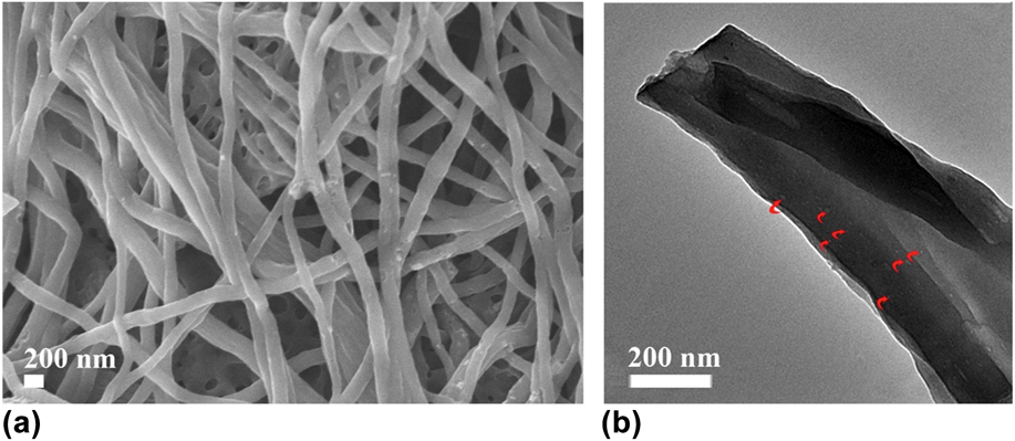
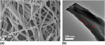
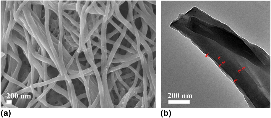
Figure 1 shows the morphologies of the prepared CNFs characterized by SEM and TEM. It was found that the diameter of CNF was in the range of 150–200 nm with a smooth and uniform surface instead of some typical microdefects such as cracks, notches, surface uplift, or depression, and there was no melting hole and skin core structure [Fig. 1(a)]. CNFs were independent while interlaced with each other like a net due to which the CNFs were inherited with polymer NFs from electrospinning after preoxidation and carbonation processes. The TEM image of CNFs, as shown in Fig. 1(b), exhibited the uniform structure of NFs and a large number of pores in the bulk of CNFs [marked with red arrows in Fig. 1(b)]. Other samples had the similar morphology. These micropores and mesopores were produced from the fast solvent exchange and the removal of PVP macromolecules during the phase-separation process and annealing process at high temperature. Meanwhile, these pores could improve the surface area and provide the channel or place admitting electrolyte ion access leading to a higher specific capacitance and better electrochemical kinetic process.
(a) SEM and (b) TEM images of CNFs.
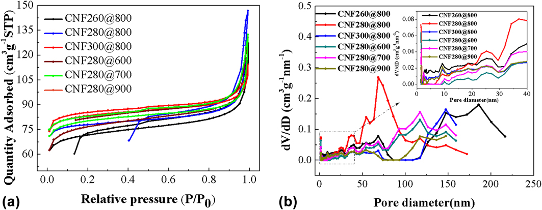
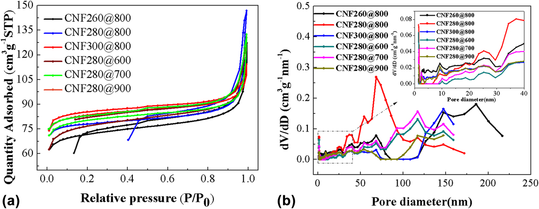
During the process to produce carbon materials, the thermal treatment contained the annealing treatment in air and high temperature under N2 atmosphere. The first annealing treatment was named preoxidation and the second high temperature treatment was called as carbonation to distinguish easily. The temperature in each step was very important for the structure, especially for the porous structure and pore distribution. We chose different preoxidation temperatures of 260, 280, and 300 °C under the same carbonation temperature of 800 °C. The obtained samples were noted as CNF260@800, CNF280@800, and CNF300@800, respectively. On the other hand, we also chose different carbonation temperatures of 600, 700, 800, and 900 °C under the same preoxidation temperature of 280 °C, and the prepared samples were marked as CNF280@600, CNF280@700, CNF280@800, and CNF280@900, respectively. To investigate the effects of preoxidation and carbonation temperatures on the pore structure and pore-size distribution, nitrogen adsorption/desorption isotherms at 77 K were carried out and the data are shown in Fig. 2 and Table I.
(a) N2 adsorption/desorption isotherms and (b) the pore diameter distribution curves of the prepared CNFs.
Pore structural parameters of CNFs at different heat-treatment temperatures.

S BET: the specific surface area; S micro: the micropore specific surface area; S ex: the external specific surface area; V t: the total volume; and V micro: the microporous volume.
The corresponding adsorption and desorption isotherms of all samples are shown in Fig. 2(a). All adsorption and desorption isotherms had a similar shape and showed lower adsorption quantity at the relative pressure P/P 0 lower than 0.85. When the pressure P/P 0 was greater than 0.85, the adsorption quantity sharply increased. Besides, there was an obvious hysteresis loop between the adsorption isotherms and desorption isotherms indicating the existence of the mesopore. The pore distributions of all samples are shown in Fig. 2(b). It can be seen that the pore size is mainly in the range of the mesopore together with certain micropores and macropores. The pore structural parameters of CNFs at different preoxidative and carbonation temperatures are shown in Table I. With the preoxidation temperature increasing from 260 to 300 °C, the specific surface areas were 207.9, 222.4, and 238.8 m2/g, respectively, and the average pore sizes were 10.05, 8.66, and 10.39 nm, respectively. Besides, the obtained CNF280@800 had a higher total volume (0.162 cm3/g) than the other two samples (0.151 cm3/g for CNF260@800 and 0.155 cm3/g for CNF300@800). These differences were caused by preoxidation temperature owing to cyclization in molecular level (Fig. S1).Reference Shokuhfar, Sedghi and Farsani60 In addition, it was significantly that with the carbonation temperature increasing from 600 to 900 °C, the specific surface areas were 236.2, 230.4, 222.4, and 102.3 m2/g, respectively, and average pore sizes were 9.96, 13.50, 8.66, and 10.42 nm, respectively. The average pore sizes were mainly in the range of 8.66–13.50 nm, which was in the mesopore scope and consisted with the pore-size distribution curves. CNF280@900 had a smaller specific surface area owing to the fact that higher temperature destroys the pore structure leading to the decrease of the specific surface area. Meanwhile, it suggested smaller specific capacitance and poor electrochemical performance for CNF280@900. Besides, CNF280@600 had a higher specific surface area, but carbonization was not complete at the lower carbonation temperature of 600 °C.Reference Xue, Zhong, Cheng and Wang54
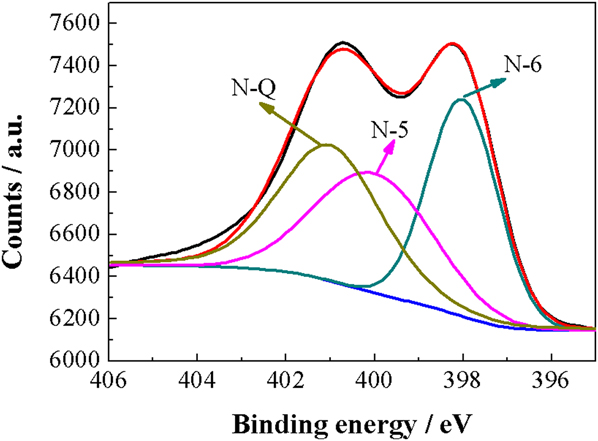
Besides, high-resolution XPS of N 1s were measured and the results are shown in Fig. 3. N 1s XPS contained three characteristic peaks at 398, 400, and 401 eV, which scripted to pyridinic (N-6), pyrrolic (N-5), and graphitic (N-Q) nitrogen, respectively. And N content in the material was 5.29 at.%. The fraction of N-5 and N-Q was important for the application in EDLCs due to their positive contributions to pseudocapacitance, wettability, and hydrophilicity.Reference Kim, Kang, Joo, Kim, Song, Kim, Yoon and Yi40,Reference Lin, Chen, Liu, Yang, Bi, Xu and Huang41
High-resolution XPS of N 1s.

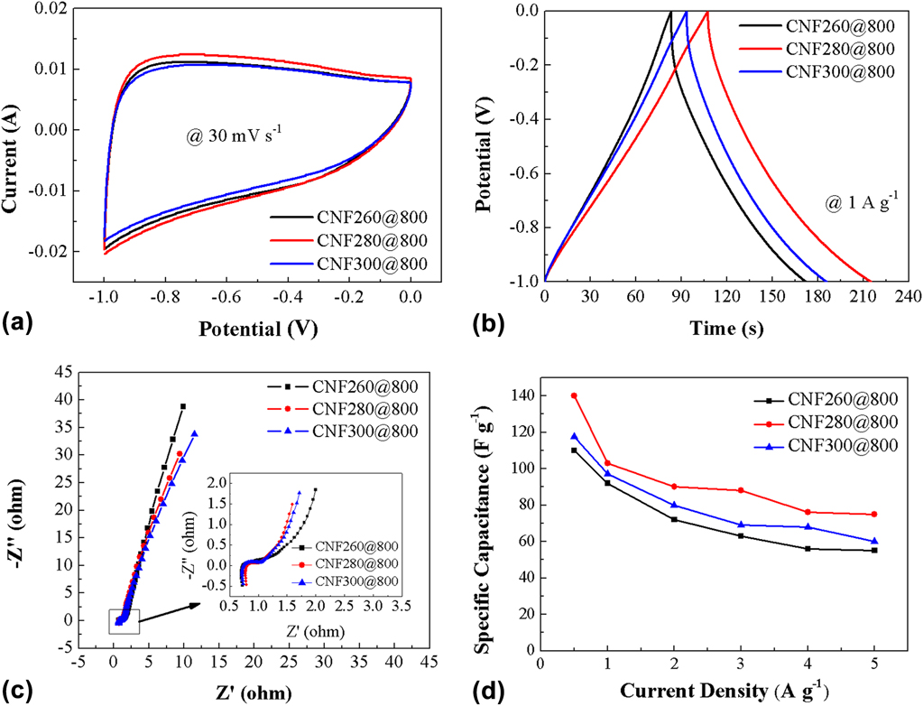
The electrochemical performances of CNF260@800, CNF280@800, and CNF300@800 fabricated at different preoxidative temperatures are shown in Fig. 4. In the cyclic voltammetry curves of all the samples, it showed nearly rectangular shapes without obvious distortion and apparent redox peaks [Fig. 4(a)]. This result indicated a typical electrical double-layer behavior in a 2 M KOH aqueous solution at the scanning rate of 30 mV/s. Furthermore, the maximum area surrounded in the cyclic voltammetry curve of CNF280@800 implied the higher specific capacitance than these of the other obtained samples.Reference Lin, Chen, Liu, Yang, Bi, Xu and Huang41 To acquire accurate specific capacitance, the galvanostatic charging/discharging curves were tested in 2 M KOH between −1 and 0 V at the current density of 1 A/g for above obtained samples as shown in Fig. 4(b). It showed that the potential increased with the increase of time linearly between −1 and 0 V and then decreased with time increasing linearly between 0 and −1 V. In summary, the linear relationship of potential and time and the symmetrical triangular shape were obviously obtained indicating the electrical double-layer behavior. This agreed with the results of the cyclic voltammetry curves. Based on Eq. (1), the specific capacitance of CNFs can be calculated to be 92, 103, and 97 F/g for CNF260@800, CNF280@800, and CNF300@800 at the current density of 1 A/g, respectively. Meanwhile, another sample was prepared without the preoxidation process; however, its electrochemical performance was not good, which only delivered a specific capacitance of ∼7 F/g (Fig. S2). This showed the importance of the preoxidation process for PAN fibers from open chain polymers to ladder polymers in this stage.Reference Shokuhfar, Sedghi and Farsani60 The specific capacitance of CNF280@800 was obviously higher than that of the other two obtained samples of CNF260@800 and CNF300@800. This result was also consisted with the surrounding area of cyclic voltammetry curves. Besides, with the preoxidative temperature increasing from 260 to 300 °C, the specific capacitance first increased from 92 to 103 F/g and then decreased to 97 F/g at the current density of 1 A/g owing to different cross-link degree at different annealing temperature. Lower preoxidation temperature led to high N content and lower specific surface area; however, higher preoxidation temperature led to low N content and high specific surface area. CNF280@800 delivered the highest specific capacitance owing to synergistic combination of N content and specific surface area. So, the preoxidative temperatures before the carbonation process had a critical influence on specific capacitance. The electrochemical impedance spectra (EIS) of the above three samples were measured and the results are shown in Fig. 4(c). It was clearly shown that the curves included a small semicycle at a higher frequency region and a line at a lower frequency region. All radius of semicycle of CNFs were small ones, indicating the good charge transfer ability of the electrode materials. Moreover, the slopes of the line were close to the vertical line suggesting good capacitor behavior. Figure 4(d) shows the specific capacitance at different current densities. From the curves, one can see that CNF280@800 delivered the highest specific capacitance at any current density. The specific capacitances of CNF260@800, CNF280@800, and CNF300@800 were 110, 140, and 117 F/g at the current density of 0.5 A/g, respectively. When the current density increased to 5 A/g (10 times the intimal current density), the specific capacitances were observed to be 55, 75, and 60 F/g, respectively. The specific capacitance retentions were 50, 53.5, and 51.3% for CNF260@800, CNF280@800, and CNF300@800, respectively. Based on the above results, the proper preoxidative temperature was 280 °C.
(a) Cyclic voltammetry curves at the scan rate of 30 mV/s, (b) charging/discharging curves at the current density of 1 A/g, (c) electrochemical impedance spectra, and (d) specific capacitance at different current densities of CNF260@800, CNF280@800, and CNF300@800.

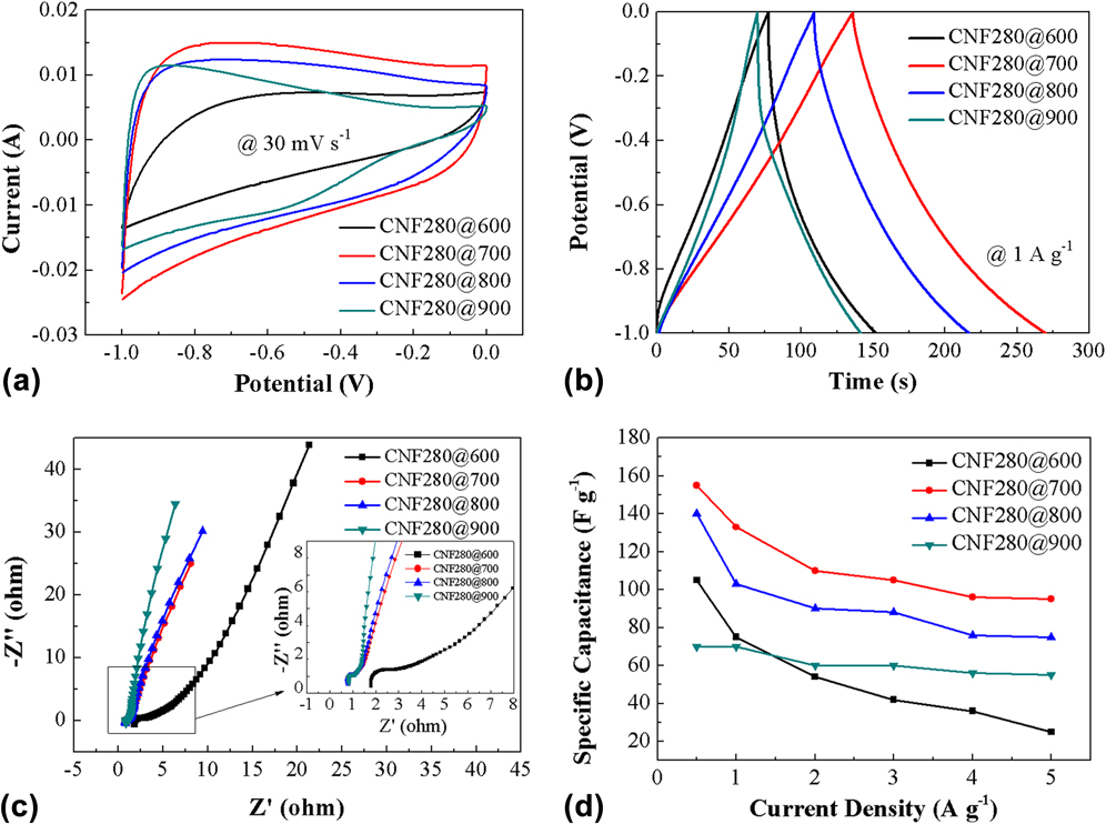
In addition, the carbonation temperature also has an important influence on the carbon structure and electrochemical performance. The electrochemical performances of CNF280@600, CNF280@700, CNF280@800, and CNF280@900 prepared at different carbonation temperatures were investigated and shown in Fig. 5. From Fig. 5(a), one can see that the shape of cyclic voltammetry curves measured at the scan rate of 30 mV/s showed quasi-rectangular shapes. With the carbonation temperature increasing from 600 to 900 °C, the surrounding area within the cyclic voltammetry curves varied, which reflected specific capacitance changing at different carbonation temperatures. The galvanostatic charging/discharging curves were measured at the current density of 1 A/g for the above obtained samples as shown in Fig. 5(b). It showed that the potential increased with the increase of time linearly between −1 and 0 V and then decreased linearly between 0 and −1 V. In summary, the linear relationship of potential and time and the symmetrical triangular shape were obviously seen. These results also indicated the electrical double-layer behavior, which was consist with the results of their cyclic voltammetry curves. According to Eq. (1), the specific capacitances of CNF280@600, CNF280@700, CNF280@800, and CNF280@900 were calculated to be 105, 155, 140, and 70 F/g, respectively. Figure 5(c) shows the EIS of CNFs prepared at different carbonization temperatures; CNF280@600, CNF280@700, CNF280@800, and CNF280@900 had similar impedance spectra performance. However, CNF280@600 exhibited larger internal resistance (R s) and charge transfer resistance (R ct) than those of the other samples because lower carbonation temperature could not make the sample carbonize completely. Figure 5(d) shows the specific capacitance at different current densities. From the curves, one can see that CNF280@700 delivered the highest specific capacitance at any current density. The specific capacitance of CNF280@600, CNF280@700, CNF280@800, and CNF280@900 were 105, 155, 140, and 70 F/g at the current density of 0.5 A/g, respectively. With the carbonation temperature increase from 600 to 900 °C, the specific capacitances was first increased from 105 to 155 F/g on the basis of temperature of 600–700 °C and decreased to 70 F/g at high temperature of 900 °C. Lower carbonation temperature could not carbonize the precursors completely, and higher temperature made the sample structure to be destroyed leading to specific capacitance decreased. When the current density increased to 5 A/g (10 times of intimal current density), the specific capacitances were observed to be 25, 95, 75, and 55 F/g, respectively. The specific capacitance retentions were 23.8, 61.3, 53.5, and 78.5% for CNF280@600, CNF280@700, CNF280@800, and CNF280@900, respectively.
(a) Cyclic voltammetry curves at the rate of 30 mV/s, (b) charging/discharging curves at the rate of 1 A/g, (c) electrochemical impedance spectra, and (d) specific capacitance at different current densities for CNF280@600, CNF280@700, CNF280@800, and CNF280@900.

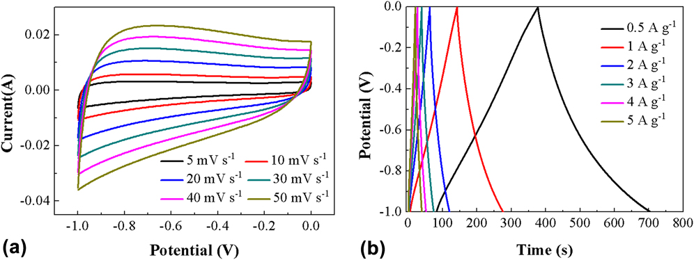
Based on the above results and discussion, we obtained an optimized condition to fabricate the electrode material of CNFs with rational pore distribution, which exhibited better electrochemical performance as supercapacitor electrode material. The optimized temperatures were preoxidative temperature of 280 °C, and carbonation temperature of 700 °C, that is, the sample of CNF280@700. And the electrochemical performance of CNF280@700 sample is shown in Fig. 6. The cyclic voltammetry curves reflected rectangular shapes, indicating a typical electrical double-layer behavior [Fig. 6(a)]. With the scan rate increasing from 5 to 50 mV/s, the shapes of cyclic voltammetry curves still remained rectangular types. This indicated that the CNFs had good specific capacitance retention. The charging/discharging curves at different current densities are shown in Fig. 6(b), and the linear relationship of potential and time indicated the electrical double-layer behavior.
(a) Cyclic voltammetry curves at different scan rates and (b) charging/discharging curves at different current densities of CNF280@700.

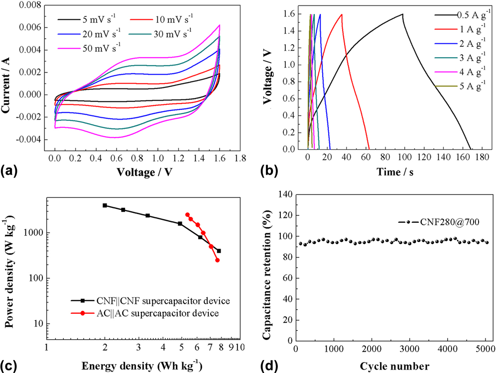
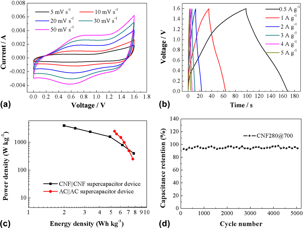
The three-electrode test system could reflect the electrochemical performance of a single electrode. To exhibit electrochemical performance better and consider the practical application, the symmetric supercapacitor device was assembled by using CNFs both as the positive electrode and negative electrode. 0.5 M Na2SO4 was chosen as an electrolyte to achieve a larger voltage window in the range of 0–1.6 V. Figure 7 shows the electrochemical performance of the assembled supercapacitor device. In Fig. 7(a), the cyclic voltammetry curves showed nearly rectangular shapes. With the scan rate increasing from 5 to 50 mV/s, the cyclic voltammetry shape still remained rectangular types, indicating EDLC. The charging–discharging curves of the device as shown in Fig. 7(b) exhibited that the linear relationship between voltage and time is EDLC. On the basis of Fig. 7(b) and according to Eq. (1), the specific capacitances were calculated to be 21.9, 17.5, 13.8, 9.4, 7.0, and 5.6 F/g at the current density of 0.5, 1, 2, 3, 4, and 5 A/g, respectively. Noted that based on Eq. (1), m was the total mass of two electrodes. The relationship between energy density and power density, called the Ragone plot, as shown in Fig. 7(c) was calculated using Eqs. (5) and (6) based on the charging/discharging time. The CNF‖CNF symmetric supercapacitor device showed the maximum energy density of 7.78 W h/kg with the power density of 400 W/kg at the current density of 0.5 A/g. When the current density increased to 5 A/g, the energy density decreased to 2.0 W h/kg with the power density of 4000 W/kg. The AC‖AC supercapacitor device showed an energy density of 7.63 W h/kg with a power density of 250 W/kg.Reference Tan, Liu, Kong, Kang and Ran13 The maximum power density of the AC‖AC supercapacitor device delivered 2500 W/kg. In contrast, the CNF‖CNF supercapacitor device had a better electrochemical performance than that of the AC‖AC device. Actually, the carbon‖carbon symmetric supercapacitor device showed energy density <10 W h/kg.Reference Wang, Song and Xia45,Reference Zhang and Pan61 Figure 7(d) shows the cycle life of the CNF‖CNF symmetric supercapacitor device at the current density of 1.25 A/g. It was obvious that after 5000 cycle numbers, specific capacitance retained 91% of the initial specific capacitance, reflecting the good cycle life.
(a) Cyclic voltammetry curves at different scan rates, (b) charging/discharging curves at different current densities, (c) Ragone plots of CNF‖CNFs and AC‖AC supercapacitor devices, and (d) cycling life at the current density of 1.25 A/g of CNF‖CNF supercapacitor devices.
IV. CONCLUSIONS
In summary, CNFs were prepared via the electrospinning method accompanied with phase-separation. The preoxidation and carbonation temperatures during the process of preparing carbon fibers have critical effects on the electrochemical performance. Based on the investigation, the proper preoxidative and carbonization temperatures were 280 and 700 °C, respectively, which showed the highest specific capacitance of 155 F/g. The symmetric supercapacitor device delivered a maximum energy density of 7.78 W h/kg with a power density of 400 W/kg and a maximum power density of 4000 W/kg with an energy density of 2.0 W h/kg. Moreover, the cycle stability was retained 91% of initial specific capacitance after 5000 cycles.
Supplementary Material
To view supplementary material for this article, please visit https://doi.org/10.1557/jmr.2017.373.
ACKNOWLEDGMENTS
This work was partly supported by the National Natural Science Foundation of China (51203071, 51463012, and 51763014), China Postdoctoral Science Foundation (2014M552509 and 2015T81064), Natural Science Funds of the Gansu Province (2015GS05123), and the Program for Hongliu Distinguished Young Scholars in Lanzhou University of Technology (J201402).