1. Introduction
Safety and adaptability are paramount concerns in human-robot-environment interaction, driving the development of compliant actuators [Reference Yu, Fu, Yao, George, Richard and Gan1,Reference Fu, Yu, Lin and Gan2]. These actuators are primarily classified into two categories: series elastic actuator and variable stiffness actuator (VSA) [Reference Shao, Shi, Feng, Zhang and Ding3]. As a promising approach to resolving the tradeoff between safe interaction and payload capacity, VSA has attracted wide attention in fields such as extensible continuum robots, clinical medicine, and bio-inspired propulsion systems [Reference Li, Chu, Hu, Zhang, Li and Li4–Reference Ju, Li, Kang, Zhang and Song7]. The ability to adjust stiffness can reduce reflected inertias, improve the adaptability to diverse environments, enhance interaction safety, and augment versatility in performing multiple functions. For example, leveraging a variable stiffness mechanism, the robotic finger or gripper can delicately manipulate different objects, such as eggs or strawberries; fish can output high speed by switching into high stiffness or maintain high efficiency under low-stiffness conditions [Reference Obayashi, Junge, Singh and Hughes8,Reference Zhu, Zhou, Zou, Wang, Deng, Wang and Fan9]. These potential advantages have catalyzed innovations across the four dominant paradigms: antagonistic VSA, structural VSA, material-based VSA, and mechanical VSA [Reference Zhou, Shao, Shi, Feng, Ding and Zhang10–Reference Alandoli, Fan and Liu12].
The antagonistic VSA is a widely favored mechanism that adjusts stiffness by controlling actuators in opposite directions to generate internal forces against each other. For instance, S. Liu et al. developed a robotic fish driven by a double-cylinder plunger pump [Reference Liu, Liu, Liang, Ren and Ren13], where the body stiffness is modified by altering fluid pressure. L. Yang et al. introduced a variable stiffness cable-driven elbow exoskeleton by mimicking the antagonistic actuation of the human elbow muscles [Reference Yang, Zhang and Fu14]. The stiffness was controlled by regulating the antagonistic actuation relationship between the left input wheel and the right input wheel. The structural VSA adjusts stiffness by modifying the geometry of its elastic components. X. Liao et al. utilized spring steel to simulate the elastic spine of robotic fish, adjusting its stiffness by regulating the effective length of the spring steel [Reference Liao, Zhou, Cheng, Wang, Fan and Zhang15]. J. Fu et al. designed a variable stiffness robotic gripper by altering the effective length of the parallel beams participating in the system [Reference Fu, Yu, Guo, Zheng and Gan16]. The material-based VSA tunes stiffness by altering the intrinsic properties of elastic materials. With the advancement of smart materials, this approach holds great promise for future applications. In the field of robotic arms, techniques such as particle jamming, layer jamming, and phase change are commonly employed to modify stiffness [Reference Zhu, Xie, Mori, Dai, Kawamura and Yue17–Reference Lin, Song and Wang20]. The mechanical VSA adjusts stiffness by changing the pre-tension in its elastic components. B. Vanderborght proposed and enhanced the mechanically adjustable compliance and controllable equilibrium position actuator (MACCEPA) [Reference Van Ham, Vanderborght, Van Damme, Verrelst and Lefeber21–Reference Jimenez-Fabian, Flynn, Geeroms, Vitiello, Vanderborght and Lefeber23]. MACCEPA operates as a parallel mechanism with a rotational singularity, effectively converting the prestress of elastic elements into active stiffness in the rotational direction, thus offering a strong capacity for stiffness modulation. C. Qiu et al. and Ziegler et al. independently developed variable stiffness swimming platforms based on MACCEPA [Reference Ziegler, Hoffmann, Carbajal and Pfeifer24,Reference Qiu, Wu, Wang, Tan and Yu25].
The antagonistical VSA mimics the muscle-driven joint found in biological systems. However, it suffers from a limited range of stiffness and angular adjustment and faces challenges in achieving independent control of stiffness and motion. The structural VSA enables rapid stiffness modulation, but a major drawback of this approach is the inherent coupling between stiffness and geometry. In most cases, significant changes to the shape of a pre-designed mechanism are undesirable. The material-based VSA often requires additional pneumatic systems or magnetic field generators, complicating efforts to achieve miniaturization and lightweight designs. The mechanical VSA features relatively simple structure and control, enabling a wide range of stiffness adjustments. In a comparative study of five commonly used mechanical VSAs, B. Vanderborght et al. concluded that the MACCEPA structure is simple, energy-efficient, and exhibits minimal power consumption [Reference Vanderborght, Van Ham, Lefeber, Sugar and Hollander26]. Moreover, it allows for the decoupling of stiffness from motion. Nevertheless, two main challenges persist: first, when the spring element is removed, the structure becomes rigid, reducing overall flexibility; second, direct mechanical contact between rigid components results in increased friction losses at the joints.
A well-designed variable stiffness planar rotational mechanism should fulfill several critical criteria: good flexibility, online stiffness adjustment, broad stiffness variation range, high mechanical efficiency, and scalability to multi-degree-of-freedom systems. Based on the above analysis of current VSAs, MACCEPA demonstrates a greater advantage. However, it also shares common limitations with traditional rigid joints, such as joint friction and restricted flexibility. The issues are addressed in this paper by replacing conventional rigid joints with a tensegrity structure. A tensegrity structure consists of compressed rod elements and tensile cable elements, where the rods typically remain non-contacting. The stability of the structure is maintained through pre-stress within the cable network. Owing to the high load-bearing capacity, lightweight design, and ease of modularization, tensegrity structures have been increasingly applied in the robotics field in recent years [Reference Layer, Denning and Hill27–Reference Zheng, Asano, Yan, Li and Tokuda31]. By definition, tensegrity structures derive their structural integrity from tension alone and avoid static or sliding friction between rigid components. This intrinsic characteristic enables them to minimize friction losses typically caused by direct contact between rigid parts. Y. Hao et al. proposed a low-inertia and reduced-friction soft tensegrity robot joint for use in a serial-link manipulator [Reference Hao, Wang, Song, Li, Fu, Lee, Cheung, Lam and Kwok32], while B. Chen et al. designed a tensegrity joint to reduce friction losses and increase transmission efficiency in robotic fish applications [Reference Chen, Jiang, Liu and Lu33,Reference Chen and Jiang34]. Therefore, tensegrity-based joints not only greatly enhance reliability but also mitigate the friction issues inherent in traditional rigid joints while retaining the same degree of compliance as elastic joints. The total stiffness of a tensegrity joint comprises passive stiffness, determined by the elasticity of the springs and kinematic parameters, and active stiffness, which allows for adjustment by modulating the antagonistic forces in the cables. Nevertheless, research shows that passive stiffness largely dominates the total rotational stiffness, with the adjustable range of active stiffness being quite limited [Reference Chen, Jiang, Liu and Lu33]. As a result, tensegrity-based joints face considerable technical challenges in achieving high stiffness controllability and a broad range of stiffness variation.
To synergize the complementary strengths of mechanical VSA and tensegrity structure while addressing their respective limitations, a novel variable stiffness tensegrity-based compliant actuator (VSTCA) is proposed in this paper. In this design, different MACCEPA variants are employed to meet diverse practical requirements and to enable active stiffness adjustment, while the tensegrity-based joint improves compliance and minimizes mechanical friction. Our work addresses three limitations identified in the previous tensegrity-based joint design by B. Chen et al., which featured a Y-shaped foot for robotic fish applications and decoupled translational stiffness and rotational stiffness within a tension network [Reference Chen and Jiang34]. First, the original Y-shaped configuration is redesigned into the Π-shaped foot orthogonally connected to a rigid hollow plate, expanding the internal workspace to accommodate functional modules necessary for task execution. Second, the MACCEPA is integrated into the joint to enable a wide range of stiffness adjustment. Third, a steering motor is employed to adjust the joint stiffness online by controlling the motor’s rotation angle, thereby eliminating the need for manual spring replacement to change stiffness.
The remainder of this paper is organized as follows. Section 2 presents the theoretical analysis and experimental validation of a single-joint VSTCA. Section 3 proposes three multi-joint configurations derived from VSTCA, thereby extending its application scope. Section 4 discusses the advantages and disadvantages of these configurations. Finally, conclusions are summarized in Section 5.
2. Analysis and experiment of single-joint VSTCA
2.1. The structure design and working principle
The schematic of VSTCA, which integrates a tensegrity-based joint with MACCEPA, is shown in Figure 1. This joint consists of a fixed part, a follower member, two axial elastic elements, and four radial elastic elements. The materials of these elastic elements are selectable from elastic thread (e.g., fishing line), linear spring, artificial muscle, or shape memory alloy. By individually tensioning each element, an antagonistic tension network is formed, creating a floating connection between the fixed part and the follower member. The MACCEPA structure is assembled from steering motor A, steering motor B, strings, springs, the fixed part, and the follower member. Steering motor A drives the joint’s rotation, while steering motor B adjusts the pre-tension in the spring, providing precise control over the rotational stiffness of VSTCA. The rotation axis of the tensegrity-based joint is aligned with that of the MACCEPA structure.
The sketch of VSTCA.

The VSTCA is fundamentally a tensegrity structure based on a prestressed elastic system in a rotational singular configuration [Reference Azadi, Behzadipour and Faulkner35]. The internal forces in this configuration are fully dedicated to generating rotational stiffness. By actively adjusting the spring pre-tension force via steering motor B, the mechanism’s stiffness can be tuned both effectively and simply. Under these conditions, the adjustable range of the active stiffness depends solely on the mechanism’s strength and dimensions. On the other hand, as the VSTCA rotates, positional changes alter the internal forces in the elastic elements of the tension network, thereby affecting the joint’s passive stiffness. The coupling between active and passive stiffness influences the overall controllability of the joint stiffness. A detailed stiffness analysis for VSTCA is provided in Section 2.2.
2.2. Stiffness analysis of VSTCA
Figure 2 illustrates the connection of the elastic component in the VSTCA. The coordinate system Oxyz is established, with the origin O located a distance h from the base of the follower member. For a tensegrity-based joint, the axial elastic elements l 1 and l 2 are anchored at points A 1 B 1 and A 2 B 2, respectively. Meanwhile, the radial elastic elements l 3∼l 6 are attached at points C 1 D 1, C 2 D 1, C 3 D 2, and C 4 D 2, respectively. c denotes the circumradius of points C 1∼C 4, while γ represents the acute angle formed between these points and the y-axis. The elastic coefficient of l 1∼l 6 is represented by k 1. The left end E of the MACCEPA structure is fixed to the fixed part, and the right end J is secured to the follower member. Points E, D 1, and D 2 are collinear. Links EF and IJ serve as the arms of steering motors A and B, with lengths L A and L B, respectively. Point G represents a fixed hole on the follower member. The distance from point J to the line A 1 A 2 (namely GJ) is L J . A spring with elastic coefficient k 2 is attached to points F and G via a string at both ends.
Schematic of the elastic element connections.

Three variants of the MACCEPA structure. (Top: initial state, bottom: motion state).

The MACCEPA structure features several variants designed for different application scenarios, as shown in Figure 3. We refer to these structures in Figure 3 as Variant 1, Variant 2, and Variant 3, respectively. In Variant 1 (also shown in Figure 2), the spring is positioned between points F and G, offering a space-saving design ideal for multi-joint systems. Variant 2 places the spring between points G and I. Variant 3 is a passive variable stiffness structure, where the arm EF rotates to pre-tension the spring. The rotational stiffness of link IJ, which rotates under external force, is determined by the rotation angle of arm EF. Q. Zhong et al. utilized this variant to regulate the stiffness of a robotic tuna’s tail fin [Reference Zhong, Zhu, Fish, Kerr, Downs, Bart-Smith and Quinn36]. These three variants will be used in Sections 2.2 and 3. Despite the structural differences, all variants follow the same analytical methods and operate based on the same variable stiffness principle. The working principle of the MACCEPA structure is analyzed using Variant 1 as a representative case.
Initially, steering motor B rotates by an angle
 $\beta$
, producing a pre-tension force p in the spring. When the mechanism moves, that is, when steering motor A rotates by a certain angle, the internal force of the spring is:
 \begin{align} F&=k_{2}\biggl[\sqrt{L_{\mathrm{A}}^{2}+\left(H_{0}+H\right)^{2}-2L_{\mathrm{A}}\left(H_{0}+H\right)\cos \alpha }-\left(H_{0}+H-L_{\mathrm{A}}\right)\nonumber\\ &\quad+\sqrt{L_{J}^{2}+L_{\mathrm{B}}^{2}-2L_{J}L_{\mathrm{B}}\cos \beta }-\left(L_{J}-L_{\mathrm{B}}\right)\biggr]\end{align}
where H is the axial separation between A 1 and B 1 along the z-axis and H 0 is the perpendicular distance from the line segment D 1 D 2 to the fixed part, as shown in Figure 2. Thus, the sum of H and H 0 equals the distance between points E and G, as shown in Figure 3. α denotes the angle between link EF and the follower member. α decreases with increasing k 2.
The mechanism’s rotational stiffness K M is derived through the law of sines.
 \begin{equation} K_{M}=\partial T/\partial \alpha =\partial \left[FL_{\mathrm{A}}\left(H_{0}+H\right)\sin \alpha /\sqrt{L_{\mathrm{A}}^{2}+\left(H_{0}+H\right)^{2}-2L_{\mathrm{A}}\left(H_{0}+H\right)\cos \alpha }\right]/\partial \alpha \end{equation}
where T is the torque applied at point G of the follower member.
In practical, α is a small angle (generally less than 15
 $^{\circ}$
) for two reasons. First, VSTCA joints are usually used in multiples to construct robotic arms or bio-inspired structures. As a result, the rotation angle required from an individual joint is reduced, leading to a smaller α. Second, when the external load and joint stiffness are properly matched – meaning high stiffness for large loads or low stiffness for small loads – α tends to remain small. Therefore, the expression for K
M
simplifies to the following equation.
 \begin{equation} K_{M}=\frac{L_{\mathrm{A}}\left(H_{0}+H\right)}{H_{0}+H-L_{\mathrm{A}}}\cdot k\left[\sqrt{L_{J}^{2}+L_{\mathrm{B}}^{2}-2L_{J}L_{\mathrm{B}}\cos \beta }-\left(L_{J}-L_{\mathrm{B}}\right)\right]=\mu p \end{equation}
where μ represents the stiffness amplification factor, which depends solely on the mechanism’s parameters, and p is the pre-tension force in the spring. This implies that when α is small, the rotational stiffness is approximately linear with respect to the pre-tension force. Furthermore, the rotational stiffness is independent of the rotation angle.
Next, the stiffness of VSTCA is analyzed. Based on the positions of the elastic components, vector expressions for both the axial and radial elastic elements are obtained.
 \begin{equation}l_i=RA_i-B_i (i = 1, 2), l_i=RD_j-C_k (i = 3 ~ 6, j = 1, 1, 2, 2, k = 1 ~ 4)\end{equation}
where R denotes the rotation matrix describing the movement of the follower member relative to the fixed part. The vectors A i , B i , D j , and C k extend from point O to points A i , B i , D j , and C k , respectively. Thus, the Jacobian matrix J is
 \begin{equation} \boldsymbol{J}=\left[\begin{array}{c@{\quad}c@{\quad}c@{\quad}c@{\quad}c@{\quad}c} \boldsymbol{l}_{n\mathit{1}} & \boldsymbol{l}_{n\mathit{2}} & \boldsymbol{l}_{n\mathit{3}} & \boldsymbol{l}_{n\mathit{4}} & \boldsymbol{l}_{n\mathit{5}} & \boldsymbol{l}_{n\mathit{6}}\\ \boldsymbol{R}\boldsymbol{A}_{1}\times \boldsymbol{l}_{n\mathit{1}} & \boldsymbol{R}\boldsymbol{A}_{2}\times \boldsymbol{l}_{n\mathit{2}} & \boldsymbol{R}\boldsymbol{D}_{1}\times \boldsymbol{l}_{n\mathit{3}} & \boldsymbol{R}\boldsymbol{D}_{1}\times \boldsymbol{l}_{n\mathit{4}} & \boldsymbol{R}\boldsymbol{D}_{2}\times \boldsymbol{l}_{n\mathit{5}} & \boldsymbol{R}\boldsymbol{D}_{2}\times \boldsymbol{l}_{n\mathit{6}} \end{array}\right]_{6\times 6} \end{equation}
where l ni represents the unit vector of l i .
The Jacobian matrix enables derivation of the VSTCA stiffness matrix K according to the stiffness theory for parallel mechanisms [Reference Azadi, Behzadipour and Faulkner35,Reference Chakarov37].
 \begin{equation} \boldsymbol{K}=\frac{\partial \boldsymbol{F}}{\partial \boldsymbol{x}}=\frac{\partial \boldsymbol{J}^{\mathrm{T}}\boldsymbol{f}}{\partial \boldsymbol{x}}=\boldsymbol{J}^{\mathrm{T}}\boldsymbol{k}_{\mathit{s}}\boldsymbol{J}+\frac{\partial \boldsymbol{J}^{\mathrm{T}}}{\partial \boldsymbol{x}}\boldsymbol{f}=\boldsymbol{K}_{\mathrm{E}}+\boldsymbol{K}_{\mathrm{G}} \end{equation}
where
F
and
f
represent the external load vector applied to the structure and the pretension force vector of the elastic elements, respectively.
k
s
is a diagonal matrix of the elastic elements’ material stiffness, and
x
is the generalized coordinate. The stiffness matrix
K
consists of two components: the material stiffness or passive stiffness
K
E, corresponding to the joint’s stiffness in its initial prestress-free state; and the antagonistic stiffness or active stiffness
K
G, arising from the repositioning (
 $\partial \boldsymbol{J}^{\mathrm{T}}/\partial \boldsymbol{x}$
) and the internal forces of elastic elements.
Since the VSTCA primarily operates within the y-O-z plane, the stiffness matrix reduces to a 3 × 3 planar stiffness matrix. When the joint is in its neutral position, where
 $\phi$
= 0,
K
is given by:
 \begin{equation} \boldsymbol{K}=\left[\begin{array}{c@{\quad}c} \boldsymbol{K}_{Tran} & \boldsymbol{K}_{CP}^{T}\\ \boldsymbol{K}_{CP} & \boldsymbol{K}_{Rot} \end{array}\right]=\left[\begin{array}{c@{\quad}c@{\quad}c} K_{y} & 0 & K_{y\varphi }\\ 0 & K_{z} & 0\\ K_{y\varphi } & 0 & K_{\varphi } \end{array}\right] \end{equation}
where
K
Tran
,
K
Rot
, and
K
CP
are the translational stiffness, rotational stiffness, and translational-rotational coupling stiffness of VSTCA, respectively. K
y
, K
z
, and K
 $_\phi$
denote the translational stiffness in the y-direction, z-direction, and rotational stiffness around the
 $\phi$
-axis, respectively. K
yφ
denotes the coupling stiffness between the y-direction and the
 $\phi$
-axis. The expressions of K
y
, K
z
, and K
 $_\phi$
are provided in Eqs. (8)–(11).
 \begin{equation} K_{y}=4k_{1}c^{2}\cos ^{2}\beta /{\mathit{l}_{\mathit{e}}}^{2}+2\tau _{a}/H+4\tau _{\mathit{r}}\left({\mathit{l}_{e}}^{2}-c^{2}\cos ^{2}\beta \right)/{\mathit{l}_{e}}^{3}\\[-12pt] \end{equation}
 \begin{equation} K_{z}=k_{1}\left(2+4H_{0}^{2}/{l_{e}}^{2}\right)+\mathit{k}_{2}+4\tau _{r}\left({l_{e}}^{2}-H_{0}^{2}\right)/{l_{e}}^{3}\\[-12pt] \end{equation}
 \begin{equation} K_{y\varphi }=4k_{1}c^{2}\cos ^{2}\beta \left(H+H_{0}-h\right)/{l_{e}}^{2}-2\tau _{a}\mathit{h}/\mathit{H}+4\tau _{\mathit{r}}\left({\mathit{l}_{e}}^{2}-c^{2}\cos ^{2}\beta \right)\left(H+H_{0}-h\right)/{\mathit{l}_{e}}^{3}\\[-12pt] \end{equation}
 \begin{equation} K_{\varphi }=K_{y}\left(\mathit{h}-\mathit{H}-H_{0}\right)^{2}+2\tau _{a}H_{0}+K_{M}\\[-12pt] \end{equation}
where l
e
refers to the length of the radial elastic element.
 $l_{e}=\sqrt{c^{2}+d^{2}+{H_{0}}^{2}-2cd\sin ^{2}\mathit{\gamma }}$
. τ
r
and τ
a are the prestress of the radial and axial elastic elements. The terms related to k in these equations correspond to the material stiffness, while the remaining terms represent the antagonistic stiffness.
To decouple the stiffness in the y-, z-, and
 $\phi$
-directions, the coupling stiffness term K
yφ
must be set to zero. Consequently, the following condition is obtained.
 \begin{equation} h=H+H_{0}-2\left(H+H_{0}\right)\tau _{a}/K_{y} \end{equation}
When k 1 is a large value, the last term in Eq. (12) becomes negligible, resulting in h=H+H 0. In this case, point O becomes the decoupling center for the three degrees of freedom, effectively serving as the virtual rotation center of the VSTCA. This configuration is justified because, for the VSTCA to function as a rotational joint, translational motion in the y- and z-directions must be constrained. A large k 1 ensures high stiffness in both the y- and z-directions.
When h = H + H
0, the first term in K
 $_\phi$
is zero, the second term represents the antagonistic stiffness associated with prestress, and the third term corresponds to the rotational stiffness generated by the MACCEPA (see Eq. (3)). Simultaneous activation of the second and third terms would introduce interference in active stiffness regulation. Moreover, employing antagonistic stiffness for stiffness adjustment in the VSTCA faces two challenges: the difficulty in precisely controlling internal forces and the limited range and controllability of stiffness adjustment. Therefore, during joint assembly, τ
a should be minimized to approach zero, deactivating the second term. Under these conditions, K
 $_\phi$
= K
M, meaning that MACCEPA fully assumes the function of active stiffness regulation for the VSTCA. The internal forces serve two primary roles: (1) maintaining structural stability and (2) enhancing translational stiffness via Eqs. (8) and (9), effectively approximating rigid constraints.
In practical applications, maintaining a perfectly stable virtual rotation axis is challenging. Since k 1 cannot be infinitely large, the VSTCA will experience slight translational displacement, resulting in a deviation of the center of rotation. B. Chen et al. evaluated a compliant joint’s equivalence to a rigid joint using a dimensionless axis drift metric [Reference Chen, Jiang, Liu and Lu33]. Their research confirmed that the tensegrity-based joint maintains good equivalence within ≤5% dimensionless shaft drift.
When the joint is not in its neutral position (φ ≠ 0), substituting the condition h = H+H
0 into Eq. (6) yields the relationship between K
 $_\phi$
and
 $\phi$
.
 \begin{equation} K_{\varphi }\left(\varphi \right)=2k_{1}\left(\mathit{h}\mathit{H}_{0}\sin \varphi /H\right)^{2} \end{equation}
Figure 4 illustrates how K
 $_\phi$
varies with the pre-tension angle
 $\beta$
and the rotation angle
 $\phi$
of the joint. The structural parameters are as follows: a = 50 mm, c = 46.5 mm, d = 35 mm, L
A = L
B = 20 mm, L
J
= 67 mm, H = 61 mm, H
0 = 3 mm, γ = 65
 $^{\circ}$
, k
1 = 6670 N/m, and k
2 = 667 N/m. Figure 4(a) presents the exact stiffness calculations based on Eq. (2) for α = 5
 $^{\circ}$
, 10
 $^{\circ}$
, and 15
 $^{\circ}$
, as well as the approximate stiffness calculation from Eq. (3) for α = 5
 $^{\circ}$
. The four curves demonstrate a strong level of consistency. By redesigning the structural parameters, the mechanism can achieve a broader range of stiffness variation. As shown in Figure 4(b), K
 $_\phi$
increases with the joint rotation angle but remains consistently within a small range, rendering its influence negligible. For multi-joint robots, the rotation angle of each joint would be reduced. For instance, a tail-beat amplitude of 0.23 body lengths can be achieved in a four-joint robotic fish with merely 3.2
 $^{\circ}$
of rotation per joint. Under such conditions, joint stiffness remains within 0–2 × 10⁻³ N·m/rad, exerting negligible impact on the overall stiffness. Consequently, the tensegrity-based joint exhibits kinematic equivalence to a conventional rotational pair throughout its entire range of motion.
Stiffness variation in response to changes in (a) the rotation angle of steering motor B and (b) the rotation angle of the joint.

2.3. Experiment platform
The design drawing and physical model of a single-joint VSTCA are shown in Figure 5. The physical model is mounted on a 400 mm (L) × 200 mm (W) × 10 mm (T) acrylic sheet, which is fixed onto an aluminum extrusion frame measuring 400 mm (L) × 200 mm (W) × 550 mm (H). Both steering motors utilize RGD01L models powered by 7.4 V lithium batteries. Key specifications at 7.4 V include a maximum rotation angle of 180
 $^{\circ}$
, a torque output of 15 kg·cm, and an operating speed of 0.1 s/60
 $^{\circ}$
. The fixed part and follower member are fabricated by 3D printing with photosensitive resin, while the elastic elements and strings are secured with metal fasteners. The VSTCA designed for the experiments exhibits a joint motion range of ±25
 $^{\circ}$
with a stiffness adjustment range of 0–0.63 N·m/rad. The stiffness adjustment range can be tuned for specific requirements by modifying structural dimensions, spring stiffness, and pre-tension force.
The design drawing (a) and physical model (b) of a single-joint VSTCA.

Compared to Figure 1, the primary modification in Figure 5 is the adoption of Variant 2 of the MACCEPA, which allows for easier monitoring of spring length changes using an MV-UG050GM/C industrial camera (100 fps frame rate, 800 × 600 resolution) mounted 0.5 m above the mechanism. The measurement system employs monocular vision technology to capture the motion sequences, with the camera’s optical axis aligned orthogonally to the image plane. Through image processing, marker points on a calibration ruler are extracted to obtain pixel coordinates, thereby establishing a pixel-to-length conversion ratio. This approach effectively simplifies the camera calibration process. By detecting the pixel coordinates of the spring’s endpoints and applying the calibrated conversion ratio, the physical length change of the spring is computationally determined. The instantaneous central axis of the follower member can also be recognized by finding the points A 1 and B 1 shown in Figure 2, enabling the measurement of the joint rotation angle.
2.4. Experimental validation
To investigate the impact of the angle
 $\beta$
on joint stiffness, a controlled experiment was conducted with
 $\beta$
set to 15
 $^{\circ}$
, 45
 $^{\circ}$
, and 75
 $^{\circ}$
. The camera captured the motion of the VSTCA driven by steering motor A. From the recorded image sequences, data on spring length and joint rotation angle (denoted as θ
J
) were extracted, allowing for the calculation of the angle α, torque T, and stiffness K (see Figure 6). In this experiment, the maximum rotation angle of steering motor A (denoted as θ
A
) is set to 30
 $^{\circ}$
. Phase lag in stiffness modulation becomes pronounced beyond 3 Hz driving frequency, as quantified in preliminary trials. Hence, the driving frequency of steering motor A was set to 1 Hz. The spring’s elastic coefficient k was 590 N/m, and the length ratio λ = L
A/h was 4 (with the definitions of L
A and h provided in Section 2.1). Figure 6(a) shows that, when θ
A
holds constant, θ
J
increases slightly as
 $\beta$
increases, gradually approaching θ
A
. At the same time, the angle α (the difference between θ
A
and θ
J
) decreases with increasing
 $\beta$
, tending toward zero. For
 $\beta$
values of 15
 $^{\circ}$
, 45
 $^{\circ}$
, and 75
 $^{\circ}$
, the maximum values of θ
J
are 20.3
 $^{\circ}$
, 22.8
 $^{\circ}$
, and 24.7
 $^{\circ}$
, respectively, while the corresponding maximum values of α are 9.7
 $^{\circ}$
, 7.2
 $^{\circ}$
, and 5.3
 $^{\circ}$
. In general, α is negatively correlated with the load on the follower member and positively correlated with the spring’s pre-tension (i.e., the angle
 $\beta$
). As illustrated in Figure 6(c), the experimentally measured stiffness values fluctuate slightly around the theoretical predictions derived from Eq. (2), with little variation as θ
A
changes. When
 $\beta$
increases from 15
 $^{\circ}$
to 75
 $^{\circ}$
, the stiffness increases by approximately 8.6 times. Theoretically, if
 $\beta$
is further increased to 150
 $^{\circ}$
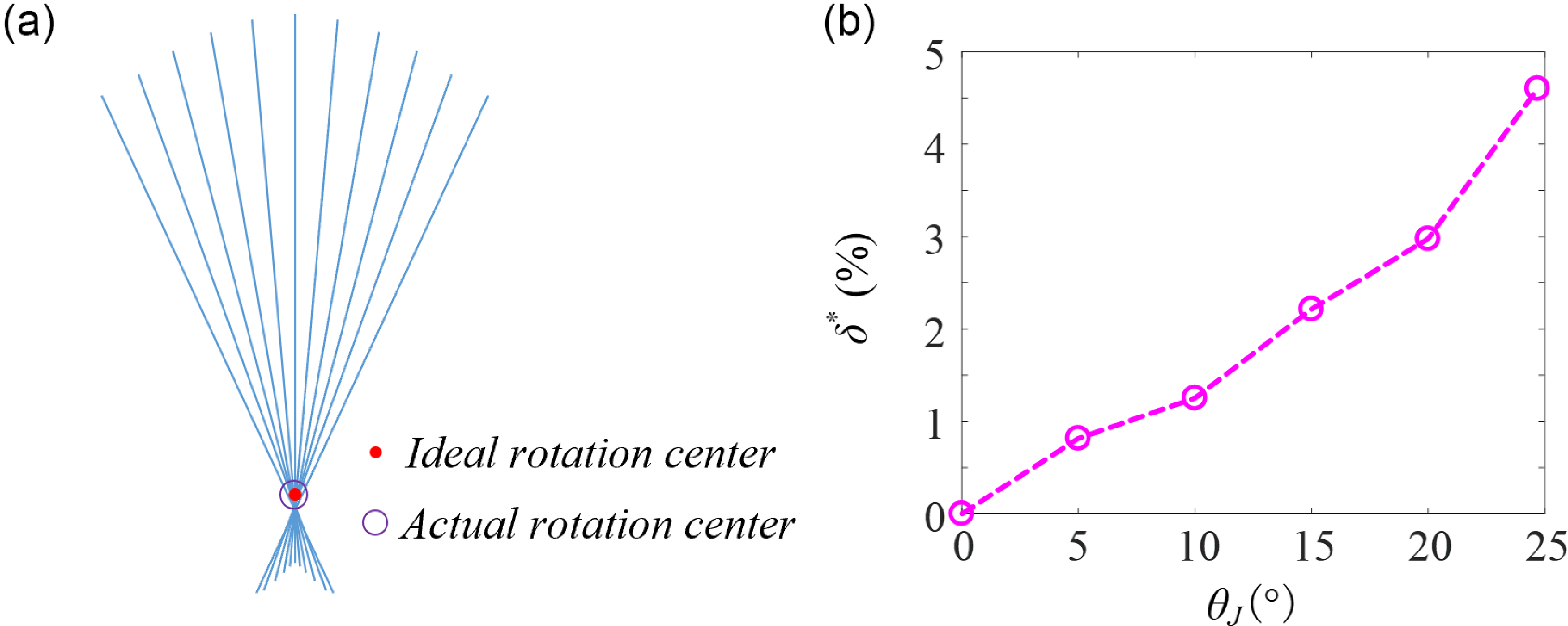
, the stiffness is expected to rise by about 15.7 times, demonstrating the VSTCA’s ability to achieve a wide range of stiffness adjustment. This experiment and the corresponding calculations omit the small rotational stiffness generated when the tensegrity-based joint is not in its neutral position. As a result, the actual rotational stiffness is likely slightly higher than the theoretical value. However, this does not affect the overall conclusions. During the VSTCA’s rotation, the maximum non-dimensional axial drift was measured at 4.7%, satisfying the joint equivalence requirement and highlighting the joint’s low axial drift characteristic.
The variations of (a) the joint rotation angle θJ and the angle α, (b) torque T acting on the joint, and (c) the joint’s rotational stiffness K, with different driving angles θA of steering motor A.

Figure 7(a) depicts the instantaneous central axis locations of the follower member during the experiment for θ
J
= 25
 $^{\circ}$
to help observe the variation in the joint rotation center. Figure 7(b) plots the computed dimensionless shaft drift δ
* of the structure for different θ
J
, revealing a rise to a maximum of 4.7% with increasing the follower member’s rotation angle. This low shaft drift characteristic demonstrates compliance with the joint equivalence requirement.
The joint rotation center variation (a) and its dimensionless axis drifts (b).

To examine the variation in joint stiffness across a wide range of angle α, the follower member was fixed with a holder, effectively simplifying the VSTCA into a basic MACCEPA mechanism, where θ
A
= α. This means that the characteristics among joint torque, stiffness, and deflection angle are investigated under static conditions. Additionally, to explore the impact of the length ratio λ on the mechanism’s stiffness, a controlled experiment was conducted with λ set to 1.5, 2, 3, and 4. The different holes in the overhanging arm of the follower member (as shown in Figure 5) define the distance between the fixed part and the follower member, thereby determining the value of h. In this experiment, the spring’s elastic coefficient was 220 N/m, and the maximum α was set to 60
 $^{\circ}$
. Figure 8 illustrates the variation of torque and stiffness with α at different length ratios, where ‘ER’ denotes experimental results and ‘TV’ represents theoretical values. The experimental data closely match the theoretical predictions. For λ = 1.5, stiffness decreases sharply with increasing α, showing a 76% reduction as α progresses from 0
 $^{\circ}$
to 60
 $^{\circ}$
. When λ = 2, stiffness first remains nearly constant for α between 0
 $^{\circ}$
and 15
 $^{\circ}$
, followed by a marked 41% decrease beyond that threshold. For λ = 3 and 4, stiffness initially increases and then decreases with α, but the overall variation is considerably smaller than in the cases of λ = 1.5 or 2. Among all cases, the smallest stiffness fluctuation occurs at λ = 3. These results suggest that both excessively small and large length ratios lead to greater stiffness fluctuations. Theoretically, there exists an optimal ratio at which stiffness remains relatively stable when α is small.
Torque and stiffness variations with respect to the angle α for different λ ratios.

Serial mechanism configuration. (a) Design drawing, (b) Physical model, (c) Locomotion performance.

Experimental studies on the single-joint VSTCA confirmed its capacity for wide-range stiffness modulation, as well as the decoupling of rotation angle from rotational stiffness. The next step involves extending the actuator to multi-joint mechanisms, further enhancing its potential for diverse applications.
3. The extension to the multi-joint mechanism
3.1. Serial mechanism configuration
The multi-joint serial mechanism is modularly constructed based on the VSTCA described in Section 2. Figure 9 presents both the design drawing and physical model of the four-joint serial mechanism. To achieve a more compact configuration, Variant 1 of the MACCEPA is employed for variable stiffness control. Each joint is equipped with two steering motors: one to control the joint’s rotation angle (referred to as the active drive servo) and the other to regulate its rotational stiffness (referred to as the pre-tensioning servo). Rubber rollers are mounted beneath each joint, allowing the mechanism to propel forward through friction. This configuration differs from the multi-joint swimming platform developed by M. Ziegler et al. [Reference Ziegler, Hoffmann, Carbajal and Pfeifer24] in two key aspects: the use of tensegrity-based joints and the ability of each joint to drive actively. By coordinating the rotation angles of these servos, the mechanism is capable of generating oscillatory motion and selectively distributing stiffness along the structure.
Wire-driven mechanism configuration. (a) Design drawing. (b) Wire-driven principle.

The pre-tensioning servo’s rotation angle is set to 10
 $^{\circ}$
, 20
 $^{\circ}$
, 30
 $^{\circ}$
, and 40
 $^{\circ}$
to showcase the variations of the mechanism stiffness. The maximum rotation angle of the active drive servo θ
A
is set to 30
 $^{\circ}$
, 45
 $^{\circ}$
, and 60
 $^{\circ}$
. Aside from phase differences, all four active drive servos share identical parameter settings, resulting in a near-sinusoidal oscillatory motion. Figure 9(c) shows how the mechanism’s average forward speed varies with different combinations of drive angle θ
A
and pre-tensioning angle
 $\beta$
. When θ
A
is 30
 $^{\circ}$
or 45
 $^{\circ}$
, the forward speed increases as
 $\beta$
grows, reaching up to a 73% improvement. The peak forward speed observed is approximately 31 mm/s, indicating that greater stiffness enhances. However, when
 $\beta$
is held constant and θ
A
is varied, the speed increase becomes less pronounced at higher θ
A
. This is likely due to larger lateral oscillations diminishing the forward component of motion. At θ
A
= 60
 $^{\circ}$
, the forward speed first increases and then decreases with increasing
 $\beta$
, suggesting that at high oscillation amplitudes, the interaction between lateral displacement and stiffness introduces a more complex influence on propulsion performance.
In this experiment, the dimensionless axial drifts of the joints increase with larger active drive angles. At θ
A
values of 45
 $^{\circ}$
and 60
 $^{\circ}$
, the drift partially exceeds the 5% design tolerance. A more effective approach would be to increase the number of serial joints, thereby reducing the required active drive angle per joint and better preserving the functional equivalence to rigid joints. To minimize structural and control complexity, only four joints were used in this study, with a primary focus on qualitative analysis. As such, the joint equivalency requirement was not strictly enforced.
This variable-stiffness, multi-joint oscillatory propulsion mechanism demonstrates strong potential for applications in areas such as pipeline inspection and bio-inspired underwater propulsion (e.g., robotic snakes or anguilliform robotic fish). Optimizing the stiffness distribution along serial joints can further enhance its propulsion performance.
3.2. Wire-driven mechanism configuration
The wire-driven mechanism configuration is illustrated in Figure 10(a). This design features a fish-inspired serial tensegrity-based structure with variable stiffness implemented at the terminal joint. The mechanism comprises four tensegrity-based joints: the first three joints replicate the fish body and enable controlled bending through an active drive servo, while the final joint, equipped with an online variable stiffness mechanism based on Variant 3 of the MACCEPA, mimics the caudal fin with adjustable rotational stiffness. To enhance compactness and facilitate integration within the internal cavity of a robotic fish’s head, the pre-tensioning servo, spring, and active drive servo are all placed at the front of the mechanism.
The bending process of the wire-driven mechanism is depicted in Figure 10(b). Wires are routed along both sides of the mechanism, connecting the arm of the active drive servo to excitation points. The driving torque generated by the servo is transmitted through the wire to these excitation points, driving rotational displacement in each joint to produce controlled bending deformation of the mechanism. Assuming identical rotation angles at all joints, the wire length variations on both sides between adjacent joints are described mathematically by:
 \begin{equation} \left\{\begin{array}{l} {\unicode[Arial]{x0394}} \mathit{w}_{l}=-d\sin \left({\Phi} /2N\right)-2\mathit{h}\sin ^{2}\left({\Phi} /4N\right)\\[6pt] {\Phi} \mathit{w}_{r}=d\sin \left({\Phi} /2N\right)-2\mathit{h}\sin ^{2}\left({\Phi} /4N\right) \end{array}\right. \end{equation}
where Δw l and Δw r denote the wire length variation of the left side and right side, respectively. N represents the number of joints in the mechanism. h indicates the gap between adjacent joints. d is the width of bilateral wires.
Given the small magnitude of Φ/4N, the quadratic term in Eq. (14) is neglected. The total change in the wire is controlled by the rotation of the servo arm, which is expressed as the following equation.
 \begin{equation} {\unicode[Arial]{x0394}} \mathit{w}_{l}=-{\unicode[Arial]{x0394}} \mathit{w}_{r}=-D\alpha /N \end{equation}
where D and α represent the length and the rotation angle of the servo arm, respectively. Therefore, the relationship between the servo’s rotation angle α and the bending angle of the end joint Φ is governed by Eq. (16).
 \begin{equation} {\Phi} =2N\cdot \arcsin \left(D\alpha /2Nd\right) \end{equation}
The variable stiffness principle has been detailed in Section 2.1. When applied to carangiform or thunniform robotic fish, hydrodynamic forces generated during body undulation induce a relative angle
 $\beta$
between the caudal fin and fish body, as shown in Figure 3. The rotational stiffness of the end joint is determined by the rotation angle α of the pre-tensioning servo and the elastic coefficient k of the spring. Figure 11 presents the bending states of the mechanism when the active drive servo rotates by 15
 $^{\circ}$
, 30
 $^{\circ}$
, and 45
 $^{\circ}$
. Figure 12 gives simulation and experimental results for the three bending states. As the rotation angle of the active drive servo increases, the mechanism’s bending deformation correspondingly intensifies. The corresponding theoretical end angles calculated from Eq. (16) are 20.3
 $^{\circ}$
, 40.6
 $^{\circ}$
, and 61.1
 $^{\circ}$
, while the experimental measurements are 23
 $^{\circ}$
, 41.5
 $^{\circ}$
, and 59
 $^{\circ}$
, respectively. This demonstrates a good agreement between simulation and experimental results. Since the experiment was conducted in air without any external load, the end joint moved in unison with the third joint, resulting in no relative angle between them.
Bending states of the mechanism at different active driving angles: (a) 15°, (b) 30 °, (c) 45°.

Simulation and experimental results for the three bending are states shown in Figure 11.

3.3. Direct-drive mechanism configuration
The direct-drive mechanism is illustrated in Figure 13(a). Inside the mechanism is a VSTCA. To conserve space, the mechanism utilizes Variant 1 of the MACCEPA (see Figure 1). Externally, the mechanism consists of four serially connected tensegrity-based joints, which are linked to the internal structure via a spar that moves freely through a central hole in the follower member of the fourth joint. The active drive servo rotates the internal mechanism’s follower member, directly driving the spar to bend the external joints. The design imposes limits on the maximum rotation angle of each external joint. Without these constraints, the entire mechanism would primarily rotate around the fixed part of the first joint. Unlike the wire-driven mechanism described in Section 3.2, where all joints rotate simultaneously by the same angle, the joints in this mechanism bend sequentially.
The direct-drive mechanism configuration. (a) Design drawing, (b) Motion trajectory of the spar end, (c) Bending state of the mechanism.

The specific bending pattern is achieved by coupling the active drive servo’s rotation angle with the maximum allowable rotation angles of the external joints, as illustrated in Figure 13(b). In this figure, O 1, O 2, O 3, and O 4 are the rotation centers for the first to fourth external joints, respectively. r 1, r 2, r 3, and r 4 denote the distances from the mechanism’s endpoint to the rotation centers of these joints, while θ 1, θ 2, θ 3, and θ 4 represent the maximum allowable rotation angles of each corresponding joint. The endpoint’s trajectory is composed of four distinct circular arcs. The first arc is centered at O 1 with a radius r 1 and angle θ 1, and subsequent arcs follow the same pattern. Although the overall trajectory is not a perfect circular arc, it closely approximates one. When all the external joints reach their maximum rotation angles, the geometric relationships determine the active drive servo’s rotation angle.
Figure 13(c) shows the bending states of the mechanism. It clearly demonstrates that the axial bending of each joint closely aligns with the polyline O 1 O 2 O 3 O 4 shown in Figure 13(b), fulfilling the intended design objective. This mechanism, based on the principle of internal single-joint actuation with external multi-joint passive response, not only effectively integrates tensegrity-based joints with the MACCEPA structure but also enables the generation of specific motion trajectories with smooth and compliant motion characteristics. This design shows promising potential for applications in fields such as variable stiffness robotic arms and bio-inspired robotic fish. In the latter case, the spar functions as the spine, the internal variable stiffness module simulates the fish’s natural stiffness adjustment, and the four serially connected external tensegrity-based joints mimic the segmented structure of the fish body.
4. Discussion
Compared to MACCEPA proposed by B. Vanderborght et al. [Reference Van Ham, Vanderborght, Van Damme, Verrelst and Lefeber21], the improvements of single-joint VSTCA manifest in two aspects: substitution of the conventional rotational joint with the improved tensegrity joint, fully leveraging the inherent advantages of tensegrity structures, and online stiffness modulation via servo-controlled spring pretension adjustment. Building on this foundation, three multi-joint VSTCA variants are introduced, and their structural features are analyzed. The serial mechanism falls under the category of multi-actuator-multi-joint mechanisms, while both the wire-driven mechanism and the direct-drive mechanism belong to the single-actuator-multi-joint mechanisms.
In the serial mechanism, each joint is equipped with its own active drive servo and pre-tensioning servo, effectively decoupling rotational stiffness from rotation angle. This setup enables precise control over stiffness distribution and the generation of desired oscillation waveforms. However, as the number of joints increases, the number of servos or motors required also rises, leading to increased space consumption. Consequently, the overall size of the mechanism grows, making control more complex and miniaturization more challenging. Moreover, achieving high flexibility through multiple segmented movements requires more joints, which in turn lengthens the mechanism.
The wire-driven mechanism uses a single servo to drive the end, generating a single-point excitation that induces forced motion and activates specific vibration modes. The mechanism draws inspiration from the research work of Y. Zhong et al. [Reference Zhong, Wang, Yang and Wang38]. They combined an active wire-driven body with a soft compliant tail to accomplish undulatory swimming. Our mechanism achieves two main advancements: the online variable stiffness capability at the end-effector and the implementation of multiple tensegrity joints to simultaneously achieve structural lightweighting and inherent compliance. The wire-driven mechanism offers advantages over the serial mechanism through reduced actuator count, simple control, superior compliance, and enhanced miniaturization capacity. This comes at the cost of segment-level stiffness programmability. The variable stiffness design analysis demonstrates that the serial mechanism is better suited for elongated-body propulsion, while the wire-driven mechanism excels in tail-beat propulsion applications. Essentially, the wire-driven mechanism functions as a planar redundant serial-parallel rotational system, providing enhanced stability. Nonetheless, in the variable stiffness module, the distance between the spring and the end joint changes during bending, causing fluctuations in the spring’s pre-tensioning force and, consequently, in the rotational stiffness. The greater the bending angle, the more pronounced the stiffness variations become. These fluctuations can only be eliminated when the number of joints is reduced to one. However, this reduction significantly diminishes the mechanism’s compliance.
The direct-drive mechanism enables smooth and flexible movement by integrating an internal VSTCA with an external passive tensegrity-based multi-joint structure that limits rotational angles, providing a precise method for generating specific oscillatory waveforms. Compared to the serial mechanism, this design achieves higher compliance within the constraints of limited length, resulting in a more compact structure and simplified control system. The main difference between the wire-driven mechanism and this mechanism is that the former adjusts stiffness at the end joint, while the latter modulates stiffness throughout the entire structure.
Analysis of these three structures’ characteristics enables targeted selection for specific scenarios. For instance, we adopted the direct-drive mechanism as the core module for the bionic robotic fish, developing a tensegrity robotic fish prototype with variable stiffness. Underwater swimming experiments were conducted to assess propulsion performance [Reference Liu, Jiang and Xu39]. The results revealed that the robotic fish achieved a maximum swimming speed of 1.2 BL/s (where BL refers to the body length of the robotic fish) at a stiffness of 780 N·mm/rad and a frequency of 2.4 Hz. The swimming performance closely resembles that of real fish, thereby validating the effectiveness of the mechanism design.
5. Conclusion
By integrating the tensegrity structure with MACCEPA, a novel VSTCA was developed. Through comprehensive theoretical and experimental analysis of the single-joint VSTCA, we confirmed that it can provide a wide range of stiffness adjustment while decoupling rotational stiffness from the rotation angle. Additionally, we derived the necessary geometric conditions for the joint to be kinematically equivalent to the rigid joint. This demonstrates that, with proper geometric parameters, VSTCA can function effectively as a variable stiffness planar rotational mechanism.
Building on this innovation, we designed three multi-joint mechanism configurations based on the VSTCA to extend its application range. Experimental studies were conducted to verify the effectiveness of these configurations. Furthermore, we analyzed the structural characteristics of these three configurations. The serial mechanism is particularly suited for robotic snakes and anguilliform robotic fish, while the wire-driven mechanism and direct-drive mechanism are ideal for mimicking carangiform and thunniform fish. In the wire-driven mechanism, the variable stiffness module adjusts the stiffness of the bionic caudal fin, whereas in the direct-drive mechanism, it modulates the stiffness of the fish body. The novel VSTCA and its multi-joint extensions benefit the design of variable-stiffness robotic arms or biomimetic oscillatory propulsion systems. Future research will focus on further developing the dynamic modeling and simulation of multi-joint VSTCA configurations to enhance predictive control capabilities while experimentally characterizing stiffness tracking performance to quantify dynamic stiffness behavior.
Author contributions
HJ put forward the framework and content of the paper; YL conducted the experiments and wrote the manuscript; and GJ and LZ revised the manuscript. All authors read and approved the final manuscript.
Financial support
This work was supported by the National Natural Science Foundation of China (Grant No. 52505306 and Grant No. 52372427).
Competing interest
The authors declare no conflicts of interest exist.
Ethical approval
Not applicable.