1. Introduction
In recent years, the field of robotics has experienced rapid development driven by advances in artificial intelligence, sensing technologies, and control methods. Among various robotic systems, underactuated systems where the number of control inputs is less than the degrees of freedom represent a classical challenge in both control theory and robotics research [Reference Bradshaw and Shao5, Reference Dai, Zoppi and Kong8, Reference He, Wang and Liu13, Reference Qin, Dai and Gogu26, Reference Salerno, Zhang, Menciassi and Dai32, Reference Spyrakos-Papastavridis and Dai35, Reference Wang and Dai41, Reference Wang, Song and Dai43, Reference Yao, Gu, Haung, Wei and Dai47]. In legged robotics, extensive research has been conducted on underactuated robots [Reference Hong, Chen and Zhang15, Reference Mao, Chen, Spyrakos-Papastavridis and Dai21, Reference Shin, Fu and Kamioka34, Reference Xiong, Reher and Ames46]. However, because of their underactuated nature, achieving static balance remains a significant challenge. To address this, studies of systems with similar dynamics and structures, such as the underactuated triple pendulum robot (UTPR), are essential. The UTPR serves as an ideal platform for developing and validating control strategies relevant to underactuated bipedal robots. The primary difficulty in controlling the UTPR arises from the inability to directly control all degrees of freedom, making static balance maintenance particularly difficult. Therefore, solving this problem requires innovative control strategies specifically designed for underactuated systems.
Traditional model-based control methods have shown promise in controlling UTPR and similar mechanisms [Reference Allione, Gkikakis and Featherstone2, Reference Cisneros and Werner6, Reference Dai and Zhao7, Reference Featherstone9, Reference Lai, Wang, Wu and Cao16, Reference Li, Guo, Fu, Chen, Han and Pan19, Reference Zhao and Dai48]. Featherstone [Reference Featherstone9] proposed a control model based on angular momentum for the underactuated inverted double pendulum, and Allione [Reference Allione, Gkikakis and Featherstone2] demonstrated its practical control performance. Lai [Reference Lai, Wang, Wu and Cao16] and Li [Reference Li, Guo, Fu, Chen, Han and Pan19] studied the control of planar and vertical underactuated triple pendulum systems, respectively. These strategies rely on precise dynamics modeling and manual tuning, which make their direct deployment on the UTPR system challenging. This is mainly due to the influence of various real-world factors, such as sensor noise, hardware imperfections, and inaccuracies in the dynamic models, which are difficult to capture in idealized conditions. To overcome these limitations and achieve an adaptable balance control for the UTPR under complex conditions, the reinforcement learning (RL) approach offers a promising alternative [Reference Sutton and Barto37]. It provides a flexible framework that enables learning optimal control policies through interaction with the environment and allows autonomous adjustment to the system dynamics. This significantly reduces the reliance on precise physical models and the requirement for manual design of control strategies. RL has demonstrated impressive performance in inverted pendulum balance control, including flying inverted pendulum [Reference Figueroa, Faust, Cruz, Tapia and Fierro10], as well as double [Reference Hesse, Timmermann, Hüllermeier and Trächtler14] and triple inverted pendulums on a cart [Reference Baek, Lee, Lee, Jeon and Han3].
In recent years, deep reinforcement learning (DRL) algorithms [Reference Fujimoto, Hoof and Meger11, Reference Haarnoja, Zhou, Abbeel and Levine12, Reference Mnih, Kavukcuoglu, Silver, Rusu, Veness, Bellemare, Graves, Riedmiller, Fidjeland, Ostrovski, Petersen, Beattie, Sadik, Antonoglou, King, Kumaran, Wierstra, Legg and Hassabis22, Reference Schulman, Wolski, Dhariwal, Radford and Klimov33] have proven to be powerful tools for solving complex control problems in fields such as autonomous driving, robotic manipulation, and footed locomotion [Reference Lee, Hwangbo, Wellhausen, Koltun and Hutter17, Reference Radosavovic, Xiao, Zhang, Darrell, Malik and Sreenath27, Reference Sun and Gao36, Reference Zhu, Xu, Chen, Deng, Zheng, Liang and Liu49]. Their ability to learn control policies in high-dimensional spaces makes DRL algorithms suitable for underactuated systems like the UTPR. RL training typically requires extensive interaction with the environment, which presents challenges in real-world applications due to time, resource, and safety constraints. To overcome these, training is initially conducted in a simulation environment, where the robot interacts with a virtual world free from physical limitations. A major challenge is ensuring that trained policies can be effectively transferred to real-world systems, which is known as the “sim-to-real” gap [Reference Peng, Andrychowicz, Zaremba and Abbeel24]. To bridge the gap arising from differences between the simulation model and the physical robot, the simulation environment and training strategy must be carefully designed to enable the learned control strategies to gradually adapt to these discrepancies [Reference Xie, Clary, Dao, Morais, Hurst and Panne45]. One effective approach is domain randomization, which introduces variability into the simulation environment to better capture real-world uncertainties and enhance the generalization of control policies across different conditions [Reference Tan, Zhang, Coumans, Iscen, Bai, Hafner, Bohez and Vanhoucke38].
In DRL, reward functions play a pivotal role in shaping agent behavior. Typical quadratic reward functions are widely used due to their smooth and continuous nature. However, such reward functions often lead to significant steady-state errors in tasks requiring precise target control [Reference Wang, Zheng and Lin42, Reference Weber, Schenke and Wallscheid44]. To address this issue, Weber [Reference Weber, Schenke and Wallscheid44] introduced an integral action state augmentation for RL controllers to simulate an integrating feedback, and Wang [Reference Wang, Zheng and Lin42] incorporated an integral term into reward functions to reduce steady-state error. Additionally, to accelerate training and improve the control performance of DRL, the concept of curriculum learning (CL) [Reference Bengio, Louradour, Collobert and Weston4] has been integrated into RL. Narvekar [Reference Narvekar, Peng, Leonetti, Sinapov, Taylor and Stone23] systematically explored the assumptions, capabilities, and goals of CL methods in RL, and Luo [Reference Luo, Kasaei and Schomaker20] introduced a precision-based continuous CL method that gradually adjusts task difficulty during the training process.
In this study, we propose a model-free RL approach for achieving balance control of the UTPR. To improve control accuracy, we incorporate an integral term for joint angle errors into the reward function, which helps reduce steady-state errors. Additionally, we introduce motor dynamics model and domain randomization into the simulation environment to ensure the robustness of the control strategy in non-ideal scenarios, though this also increases the difficulty of training. Therefore, we apply a CL strategy to accelerate training and enhance the generalization of the control policies. These techniques collectively enable more effective and adaptable balance control for underactuated systems like the UTPR. Finally, we deploy the control algorithm directly on the UTPR prototype without additional parameter tuning. The results demonstrate that the proposed CSAC-QI method successfully achieves the balance control of the UTPR in the real world.
The main contributions of this work are as follows:
-
1. This paper proposes an end-to-end control framework for the UTPR system based on the SAC algorithm, which incorporates an adaptive CL mechanism to achieve balance control in both simulation and real-world environments without relying on dynamic modeling.
-
2. To improve the steady-state performance of underactuated systems, this paper designs a dense reward function that includes an integral term of joint angle errors, effectively reducing long-term deviations and residual oscillations.
-
3. This paper presents a sim-to-real transfer strategy that integrates motor parameter identification with domain randomization, significantly narrowing the sim-to-real gap and enabling zero-shot deployment of control policies.
The remainder of this paper is organized as follows: Section 2 introduces the system modeling of the UTPR. Section 3 describes the RL controller with cumulative error penalization. Section 4 presents an adaptive curriculum strategy for sim-to-real transfer to improve the generalization and robustness of the learned policy. Section 5 details both simulation and real-world experiments on the UTPR. Finally, Section 6 discusses the results and concludes the paper.
2. System modeling of UTPR
This section presents the kinematic and dynamic modeling of the UTPR, providing the mathematical foundations essential for controller design and stability analysis.
2.1. UTPR system
As shown in Figure 1, the structure of the UTPR consists of three sequentially connected links, including one passive joint and two active joints [Reference Li, Guo, Fu, Chen, Han and Pan19]. This configuration has a higher degree of freedom than the number of actuators available, resulting in complex dynamic behavior and challenges in stability control.
Structure of the UTPR model, where
 $q_1$
is underactuated,
 $q_2$
and
 $q_3$
are actuated. The photo on the right shows our physical prototype, STANDER.

2.2. Kinematics and dynamics derivation of UTPR
Let
 $\boldsymbol{q} = [q_1, q_2, q_3]^T$
, where
 $q_i$
represents the angle of the
 $i$
-th joint. The vectors
 $\dot {\boldsymbol{q}}$
and
 $\ddot {\boldsymbol{q}}$
represent the angular velocities and angular accelerations, respectively. The dynamics of the UTPR can be described by the following equation, derived from the Euler-Lagrange formulation:
 \begin{equation} \boldsymbol{\tau } = \boldsymbol{M}(\boldsymbol{q})\, {\ddot {\boldsymbol{q}}} + \boldsymbol{C}(\boldsymbol{q}, \dot {\boldsymbol{q}}) + {\boldsymbol{f}_{\boldsymbol{ext}}}, \end{equation}
where
 $\boldsymbol{\tau }$
represents the vector of applied torques,
 ${\boldsymbol{M}(\boldsymbol{q})}$
denotes the symmetric positive-definite inertia matrix,
 $\boldsymbol{C}(\boldsymbol{q}, \dot {\boldsymbol{q}})$
includes generalized forces (such as Coriolis, centrifugal forces and gravity), and
 ${\boldsymbol{f}_{\boldsymbol{ext}}}$
denotes the external forces acting on the system. The elements of the symmetric and positive-definite inertia matrix
 $\boldsymbol{M}(\boldsymbol{q})\in \mathbb{R}^{3\times 3}$
are given by:
 \begin{equation} \left \{ \begin{aligned} M_{11}&= a_1+a_2+a_4+2a_3\cos q_2 + 2a_5\cos (q_2+q_3) + 2a_6 \cos q_3 \\ M_{12}&= M_{21}=a_2+a_4+a_3\cos q_2+a_5\cos (q_2+q_3)+2a_6\cos q_3 \\ M_{13}&= M_{31}=a_4+a_5\cos ( q_2+q_3 ) +a_6\cos q_3\\ M_{22}&= a_2+a_4+2a_6\cos q_3 \\ M_{23}&= M_{32}=a_4+a_6\cos q_3 \\ M_{33}&= a_4\\ \end{aligned} \right . \end{equation}
The elements of Coriolis and the centrifugal force matrix
 $\boldsymbol{C}(\boldsymbol{q}, \dot {\boldsymbol{q}})\in \mathbb{R}^{3}$
are as follows:
 \begin{equation} \left \{ \begin{aligned} C_1&=-a_3\left ( 2\dot {q}_1+\dot {q}_2 \right ) \dot {q}_2\sin q_2-a_5\left ( 2\dot {q}_1+\dot {q}_2+\dot {q}_3 \right ) \left (\dot {q}_2+\dot {q}_3\right ) \sin \left ( q_2+q_3 \right )\\ &-a_6\left ( 2\dot {q}_1+2\dot {q}_2+\dot {q}_3 \right ) \dot {q}_3\sin q_3-b_1\sin q_1-b_2\sin (q_1+q_2)\\&-b_3\sin (q_1+q_2+q_3)\\ C_2&=\ a_3\dot {q}_{1}^{2}\sin q_2+a_5\dot {q}_{1}^{2}\sin \left ( q_2+q_3 \right )-a_6\left ( 2\dot {q}_1+2\dot {q}_2+\dot {q}_3 \right ) \dot {q}_3\sin q_3\\ &-b_2\sin (q_1+q_2)-b_3\sin (q_1+q_2+q_3)\\ C_3&=\ a_5\dot {q}_{1}^{2}\sin \left ( q_2+q_3 \right ) +a_6\left (\dot {q}_1+\dot {q}_2\right ) ^2\sin q_3-b_3\sin (q_1+q_2+q_3)\\ \end{aligned} \right . \ \ \ \ \end{equation}
The structural parameters of the system are given by:
 \begin{align}& \left \{ \begin{aligned} a_1&=I_1+m_{1}l_{c1}^{2}+( m_2+m_3 ) l_{1}^{2} \\ a_2&=I_2+m_2l_{c2}^{2}+m_{3}l_{2}^{2} \\ a_3&=( m_{2}l_{c2}+m_3 l_2 ) l_1 \\ a_4&=I_3 + m_3 l_{c3}^{2} \\ a_5&=m_{3}l_{1}l_{c3} \\ a_6&=m_{3}l_{2}l_{c3} \end{aligned} \right . \\[5pt]\nonumber \end{align}
 \begin{align}& \left \{ \begin{aligned} b_1&=( m_1l_{c1}+m_2l_1+m_3l_1 ) g \\ b_2&=( m_2l_{c2}+m_3l_2 ) g \\ b_3&=( m_3l_{c3} ) g, \\ \end{aligned} \right . \end{align}
where
 $m_i$
,
 $l_i$
,
 $l_{ci}$
, and
 $I_{i}$
denote the mass, length, distance from the previous joint to the center of mass (CoM), and moment of inertia of link
 $i$
, respectively. Due to the underactuated nature of the UTPR, the position of the CoM is critical for stability. The position of the CoM in the x-direction
 $c_x$
can be expressed as:
 \begin{equation} c_x = \frac {1}{\sum _{i=1}^{3} m_i} \sum _{i=1}^{3} m_i c_{x,i} = -\frac {1}{mg}\left (b_{1} \sin q_{1} + b_{2} \sin (q_{1}+q_{2}) + b_{3} \sin (q_{1}+q_{2}+q_{3})\right ), \end{equation}
where
 $m_i$
represents the mass of the
 $i$
-th link,
 $m = m_1+m_2+m_3$
is the total mass, and
 $c_{x,i}$
is the horizontal position of the CoM of the
 $i$
-th link. When the UTPR reaches a stable equilibrium state, the CoM position
 $ c_x$
must be zero. At this point, the inverse kinematics of the UTPR can be computed by solving the following system of equations numerically:
 \begin{equation} \begin{cases} x = l_1 \cos q_1 + l_2 \cos (q_1 + q_2) + l_3 \cos (q_1 + q_2 + q_3) \\ y = l_1 \sin q_1 + l_2 \sin (q_1 + q_2) + l_3 \sin (q_1 + q_2 + q_3) \\ b_1 \sin q_1 + b_2 \sin (q_1 + q_2) + b_3 \sin (q_1 + q_2 + q_3) = 0 \end{cases} \end{equation}
The solution to this system of equations,
 $ \boldsymbol{q}^* = [q_1^*, q_2^*, q_3^*]^T$
, gives the joint angles for each of the three joints of the UTPR for a given end-effector position. To further characterize the dynamic properties of the system, the angular momentum of the UTPR with respect to its first joint is analyzed. The total angular momentum
 $L$
can be calculated using the following equation:
 \begin{equation} L = -mg\int {c_x}dt = [M_{11}, M_{12}, M_{13}]\dot {\boldsymbol{q}}, \end{equation}
where
 $[M_{11}, M_{12}, M_{13}]$
are the elements of the first row of the inertia matrix
 ${\boldsymbol{M}(\boldsymbol{q})}$
. When the UTPR reaches a stable state, the angular velocity is
 $\boldsymbol{0}$
, and it is evident that the total angular momentum should satisfy
 $L=0$
.
3. RL-based balance controller with cumulative error penalization
This section focuses on the design of a RL-based control strategy for the balance control of the UTPR. Figure 2 illustrates the control diagram and the training framework to balance the UTPR. It outlines the steps involved in both simulation and real-world implementations, with solid lines representing steps carried out in both environments, and dashed lines indicating those performed only in simulation. The UTPR agent continuously adapts based on environmental feedback, with the simulation providing an essential platform for learning policy before real-world deployment.
Control diagram and training framework of the UTPR.

3.1. Soft actor-critic (SAC) algorithm
The SAC algorithm is a DRL method known for its high sample efficiency and stability [Reference Haarnoja, Zhou, Abbeel and Levine12]. As one of the most widely adopted maximum entropy RL algorithms, SAC aims to simultaneously maximize the expected return and the entropy of the policy. The entropy term captures the randomness in the action distribution, helping to prevent the policy from converging to suboptimal local solutions and making it widely applicable in control systems [Reference Baek, Lee, Lee, Jeon and Han3, Reference Roohi, Mirzajani and Basse-O’Connor28–Reference Roohi, Zhang and Chen31].
The optimization objective of the SAC algorithm can be expressed as [Reference Haarnoja, Zhou, Abbeel and Levine12]:
 \begin{equation} J(\pi ) = \mathbb{E}_{(s_t, a_t) \sim \rho _\pi } \left [ \sum _{t=0}^{\infty } \gamma ^t \left ( r(s_t, a_t) + \alpha \mathcal{H}(\pi (\!\cdot | s_t)) \right ) \right ], \end{equation}
where
 $\rho _\pi$
denotes the state-action pair distribution under policy
 $\pi$
,
 $ \gamma \in [0, 1)$
is the discount factor, and
 $\alpha \gt 0$
is the temperature parameter that controls the weight of the entropy term in the objective function. The policy entropy
 $\mathcal{H}(\pi (\cdot |s_t))$
is defined as:
 \begin{equation} \mathcal{H}(\pi (\!\cdot |s_t)) = -\mathbb{E}_{a_t \sim \pi (\cdot |s_t)} [\log \pi (a_t|s_t)] \end{equation}
By tuning
 $ \alpha$
, SAC is able to balance between reward maximization and maintaining policy stochasticity.
To improve sample efficiency, SAC employs off-policy learning. Unlike on-policy methods that rely on data generated by the current policy, off-policy learning allows the algorithm to utilize historical data for training. SAC uses a replay buffer
 $\mathcal{D}$
to store samples collected from interactions with the environment and performs random sampling from it for parameter updates, significantly enhancing data utilization efficiency.
SAC uses two independent Q-networks
 $ Q_{\theta _1}$
and
 $ Q_{\theta _2}$
to evaluate state-action values, where
 $\theta _1$
and
 $\theta _2$
are the parameters of the two neural networks, respectively. To enhance training stability, SAC introduces two target Q-networks
 $ Q_{\bar {\theta }_1}$
and
 $ Q_{\bar {\theta }_2}$
. The Q-networks are updated by minimizing the following loss function:
 \begin{equation} J_Q(\theta _i) = \mathbb{E}_{(s_t, a_t, r_t, s_{t+1}) \sim \mathcal{D}} \left [ \frac {1}{2} \left ( Q_{\theta _i}(s_t, a_t) - \hat {Q}(s_t, a_t) \right )^2 \right ], \quad i=1,2, \end{equation}
where the target Q-value
 $\hat {Q}(s_t, a_t)$
is computed using the target Q-networks:
 \begin{equation} \hat {Q}(s_t, a_t) = r_t + \gamma \mathbb{E}_{s_{t+1} \sim p} \left [ \min _{i=1,2} Q_{\bar {\theta }_i}(s_{t+1}, a_{t+1}) - \alpha \log \pi _{\phi }(a_{t+1}|s_{t+1}) \right ] \end{equation}
Here,
 $s_{t+1} \sim p(s_{t+1}|s_t,a_t)$
is the next state, and
 $a_{t+1} \sim \pi _{\phi }(\cdot |s_{t+1})$
is the action sampled from
 $\pi _\phi$
. The term
 $\min _{i=1,2} Q_{\bar {\theta }_i}(s_{t+1}, a_{t+1})$
takes the minimum of the two target Q-values to mitigate overestimation bias. The entropy regularization term
 $- \alpha \log \pi _{\phi }(a_{t+1}|s_{t+1})$
encourages the policy to remain stochastic.
The policy network
 $\pi _\phi$
is updated to maximize the expected return and entropy by minimizing the following loss function:
 \begin{equation} J_{\pi }(\phi ) = \mathbb{E}_{s_t \sim \mathcal{D}} \left [ \mathbb{E}_{a_t \sim \pi _{\phi }} \left [ \alpha \log \pi _{\phi }(a_t | s_t) - \min _{i=1,2} Q_{\theta _i}(s_t, a_t) \right ] \right ] \end{equation}
SAC employs the reparameterization trick to facilitate gradient computation, expressing the action
 $a_t$
as
 $f_{\phi }(\epsilon _t;\, s_t) = \mu _{\phi }(s_t) + \sigma _{\phi }(s_t) \cdot \epsilon _t$
, where
 $\mu _{\phi }$
and
 $\sigma _{\phi }$
are the mean and standard deviation outputs of the policy network, and
 $\epsilon _t \sim \mathcal{N}(\text{0}, \text{1})$
is standard Gaussian noise.
To reduce manual tuning, SAC adaptively adjusts the temperature parameter
 $ \alpha$
by optimizing the following objective:
 \begin{equation} J(\alpha ) = \mathbb{E}_{s_t \sim \mathcal{D}, a_t \sim \pi _{\phi }} \left [ -\alpha \log \pi _{\phi }(a_t | s_t) - \alpha \bar {\mathcal{H}} \right ], \end{equation}
where
 $ \bar {\mathcal{H}}$
is the target entropy, typically set to
 $ -\text{dim}(\mathcal{A})$
, representing the desired minimum entropy. By minimizing this objective, SAC can automatically adjust
 $ \alpha$
to make the policy’s expected entropy approach the target value.
Additionally, SAC employs a soft update strategy to gradually adjust the parameters of the target Q-networks. At each update step, to avoid instability caused by sudden parameter changes, the target Q-network parameters slowly move towards the current Q-network parameters:
 \begin{equation} \bar {\theta }_i \leftarrow \tau \theta _i + (1 - \tau ) \bar {\theta }_i, \quad i=1,2, \end{equation}
where
 $ \tau$
is a small positive number, typically set to 0.005, indicating the update step size.
In summary, SAC integrates maximum entropy principles with off-policy learning to achieve a robust, sample-efficient, and stable framework for solving high-dimensional continuous control problems.
3.2. Markov decision process (MDP) formulation of UTPR
In this study, the problem of balancing control for the UTPR is formulated as an MDP, which is defined by a tuple
 $(\mathcal{S},\mathcal{A},P,R,\gamma )$
. The components of this tuple are as follows:
-
1. The state space
 $\mathcal{S}$
of the UTPR primarily relies on the sensor data, specifically the joint angles
$\boldsymbol{q}$
and their corresponding angular velocities
${\dot {\boldsymbol{q}}}$
, which are obtained from the encoders of each motor. The state space is represented as a 6-dimensional vector:(16)where the initial state
\begin{equation} {\boldsymbol{s}_\boldsymbol{t}}=[\boldsymbol{q}^T, {\dot {\boldsymbol{q}}}^\boldsymbol{T}]=[q_1,q_2,q_3,\dot {q}_1,\dot {q}_2,\dot {q}_3]\in \mathcal{S}, \end{equation}
${\boldsymbol{s}_\boldsymbol{0}}$
is the upright equilibrium point (i.e.,
${\boldsymbol{s}_0}=[0,0,0,0,0,0]$
).
-
2. The action space
$\mathcal{A}$
of UTPR is defined as a two-dimensional vector
$\boldsymbol{a}_t$
. The action space can be categorized into two modes:-
(a) Torque mode: Directly outputs the motor torques
$\tau _2$
and
$\tau _3$
for the actuated joints:(17)
\begin{equation} \boldsymbol{a}_t = [\tau _2, \tau _3] \in \mathcal{A} \end{equation}
-
(b) Position mode: Outputs the desired motor angles
$q_{2,\text{des}}$
and
$q_{3,\text{des}}$
for the actuated joints, with the motor torques
$\tau _2$
and
$\tau _3$
calculated using a PD controller:(18)
\begin{align} \boldsymbol{a}_t &= [q_{2,\text{des}}, q_{3,\text{des}}] \in \mathcal{A} \end{align}
(19)
\begin{align} \tau _i &= k_p (q_{i,\text{des}} - q_i) + k_d (\dot {q}_{i,\text{des}} - \dot {q}_i), \end{align}
where
$k_p$
and
$k_d$
are the proportional gain and derivative gain, respectively.
$\tau _i$
represents the torque of the
$i$
-th joint, with each motor’s torque constrained within the range
$\tau _i \in [-\tau _{\text{max}}, \tau _{\text{max}}]$
, where
$\tau _{\text{max}}$
is the maximum motor torque.
The state transition matrix
$P({\boldsymbol{s}_{\boldsymbol{t}+1}}|{\boldsymbol{s}_\boldsymbol{t}},{\boldsymbol{a}_\boldsymbol{t}})$
describes the probability of reaching the state
${\boldsymbol{s}_{\boldsymbol{t}+1}}$
from the state
${\boldsymbol{s}_\boldsymbol{t}}$
by taking action
${\boldsymbol{a}_\boldsymbol{t}}$
, which can be derived from the dynamics Eq. (1).Since the control objective of the UTPR is to maintain balance, the dense reward function
$r({\boldsymbol{s}_\boldsymbol{t}},{\boldsymbol{a}_\boldsymbol{t}})$
is designed to provide positive feedback at each simulation step:(20)where
\begin{equation} r({\boldsymbol{s}_\boldsymbol{t}},{\boldsymbol{a}_\boldsymbol{t}})=\boldsymbol{w}^T \boldsymbol{r}=\sum \nolimits _{i\in \{p,v,m,t,s\}} w_i r_i, \end{equation}
$\boldsymbol{w}$
represents a vector of weights assigned to each reward component
$\boldsymbol{r}$
, which consists of the rewards associated with different objectives. More specifically,
$r_{i\in \{p,v,m,t,s\}}$
represents the reward components related to the joint position, velocity, angular momentum, torque, and torque smoothness, respectively, which will be described in detail later. Each component contributes to the overall reward function according to their weight
$w_{i\in \{p,v,m,t,s\}}$
in the control process.
The discount factor
$\gamma$
closer to 1 prioritizes long-term rewards, while the value closer to 0 focuses on immediate rewards. -





3.3. Reward function formulation with cumulative error penalization
The formulation of the reward function is crucial to the success of RL algorithms, as it substantially influences both the agent’s behavior and the convergence rate. Since RL methods entirely rely on environmental observations and reward signals to learn a policy, they inevitably encounter steady-state errors when controlling joint angles. To mitigate these errors in control systems, approaches incorporating integral terms have been suggested [Reference Wang, Zheng and Lin42]. This study considers three types of reward functions: quadratic, absolute value, and quadratic with an integral component. For illustration, the reward function
 $r_p$
is specifically considered and
 ${\boldsymbol{q}_\boldsymbol{t}}$
denotes the current joint angles.
3.3.1. Quadratic (QUA) form and absolute value form
The quadratic reward function
 $r_p^{\text{QUA}}({\boldsymbol{q}_\boldsymbol{t}})$
is designed to penalize the squared difference between the current and desired joint angles, while the absolute value reward function
 $r_p^{\text{ABS}}({\boldsymbol{q}_\boldsymbol{t}})$
linearly addresses the distance between them. The equations are as follows:
 \begin{equation} \begin{aligned} r_p^{\text{QUA}}({\boldsymbol{q}_\boldsymbol{t}}) &= \exp (\!-c_p \|{\boldsymbol{q}_\boldsymbol{t}} - {\boldsymbol{q}_\boldsymbol{d}}\|^2)\\ r_p^{\text{ABS}}({\boldsymbol{q}_\boldsymbol{t}}) &= \exp (\!-c_p\|{\boldsymbol{q}_\boldsymbol{t}} - {\boldsymbol{q}_\boldsymbol{d}}\|), \end{aligned} \end{equation}
where
 ${\boldsymbol{q}_\boldsymbol{d}}$
denotes the desired joint angles and
 $c_p$
is the scaling factor that determines the sensitivity of reward to the deviation from the desired joint angles. Both types of reward functions employ an exponential decay formulation, which allows the reward to gradually diminish to zero as the error increases. The non-negative reward values ensure that the UTPR consistently receives positive feedback throughout the learning process, encouraging it to maintain balance.
3.3.2. Quadratic form with integral term (QI)
To improve the performance of the reward function and reduce steady-state errors, the quadratic form can be augmented with an integral term that accumulates the error over time. This modified reward is represented as
 $r_p^{\text{QI}}({\boldsymbol{q}_\boldsymbol{t}})$
and is given by:
 \begin{equation} r_p^{\text{QI}}({\boldsymbol{q}_\boldsymbol{t}})= \exp \left(-c_p\|{\boldsymbol{q}_\boldsymbol{t}} - {\boldsymbol{q}_\boldsymbol{d}}\|^2\right) - c_Ir_I, \end{equation}
where
 $c_I$
is a scaling factor of the integral term, providing flexibility in adjusting the influence of the accumulated error on the overall reward. The term
 $r_I$
represents the integral of the error and is defined as:
 \begin{equation} r_I = \left( \int _T^{T_{\text{max}}} (\|{\boldsymbol{q}_\boldsymbol{t'}} - {\boldsymbol{q}_\boldsymbol{d}}\|) \, dt'\right)^2 \end{equation}
This integral captures the cumulative errors of the joint angles from their desired values over the time interval
 $[T, T_{\text{max}}]$
. By integrating this integral penalty, the reward function effectively discourages sustained errors, promoting a more stable and accurate control strategy.
Compared to standard reward functions that only consider instantaneous errors, the design with an integral term penalizes the cumulative deviation from the target state. To prevent premature penalization during the adjustment phase, when the system has not yet reached the target state, a time threshold
 $T$
for the integral term is introduced. The cumulative error is only calculated when
 $t \gt T$
, enabling the integral term to concentrate on the fine-tuning stage after the system enters the equilibrium region.
The individual reward components
 $r_{i\in \{p,v,m,t,s\}}$
in Eq. (20) are defined as follows:
 \begin{equation} \left \{\!\! \begin{aligned} r_p &= \exp \left(-c_p\|{\boldsymbol{q}_\boldsymbol{t}} - {\boldsymbol{q}_\boldsymbol{d}}\|^2\right) - c_I\left( \int _T^{T_{max}} (\|{\boldsymbol{q}_\boldsymbol{t'}} - {\boldsymbol{q}_\boldsymbol{d}}\|) \, dt'\right)^2 \\ r_v &= \exp \left(-c_v\|\dot{\boldsymbol{q}_\boldsymbol{t}} - \dot{\boldsymbol{q}_\boldsymbol{d}}\|^2\right) \\ r_m &= \max \left(1 - c_m\|L\|^2,0\right) \\ r_t &= \max \left(1 - c_t\|{\boldsymbol{a}_\boldsymbol{t}}\|^2,0\right) \\ r_s &= \max \left(1 - c_s\|{\boldsymbol{a}_\boldsymbol{t}} - {\boldsymbol{a}_{\boldsymbol{t}-1}}\|^2,0\right) \end{aligned} \right ., \end{equation}
where
 $c_{i\in \{p,v,m,t,s\}}$
is the scaling constant for each reward component and acts in conjunction with
 $w_{i\in \{p,v,m,t,s\}}$
to regulate the contribution of each reward term to the final reward function. This design enables the reward function to comprehensively consider multiple control objectives, thereby evaluating and guiding the behavior of the system more reasonably.
4. Sim-to-real transfer strategy with adaptive CL
This section introduces a sim-to-real transfer approach together with an adaptive CL strategy to enhance the real-world applicability and training efficiency of the control policy.
4.1. Sim-to-real method
The UTPR exhibits significant discrepancies between simulation and reality due to its complex and highly nonlinear dynamics. Simulations often rely on ideal motor models and noise-free sensors, whereas real systems experience friction, sensor noise, delays, and parameter uncertainties. These differences can lead to failure when applying trained controllers to physical systems. To address this issue, the following sim-to-real transfer strategies are proposed to enhance the generalization and robustness of the control policy:
4.1.1. Motor dynamics model identification
To achieve a more accurate simulation of the physical system, it is necessary to develop and identify a data-driven motor dynamics model. The friction dynamics and rotor inertia, which significantly affect joint actuation but are challenging to model analytically, are identified using real-world actuator data. The friction torque at each joint
 $i$
is modeled as a composite function of angular velocity
 $\dot {q_i}$
and angular acceleration
 $\ddot {q_i}$
:
 \begin{equation} f_i = \boldsymbol{\xi }_i^\top \cdot \begin{bmatrix} s_{\text{sgn}}(\dot {q_i}) \\ \dot {q_i} \\ \ddot {q_i} \end{bmatrix},\quad i=1,2,3 \end{equation}
The vector
 $\boldsymbol{\xi }_i = [f_{s,i}, f_{v,i}, J_i]^\top \in \mathbb{R}^3$
represents the friction coefficients and rotor inertia for joint
 $i$
, including the Coulomb friction coefficient
 $f_{s,i}$
, the viscous friction coefficient
 $f_{v,i}$
, and the motor rotor inertia
 $J_i$
. The sign function
 $s_{\text{sgn}}(x)$
is defined as:
 \begin{equation} s_{\text{sgn}}(x) = \begin{cases} \text{sign}(x), & |x| \geq \epsilon \\ 0, & |x| \lt \epsilon \end{cases} \end{equation}
Here, the function
 $\text{sign}(x)$
outputs the sign of the variable
 $x$
, and the parameter
 $\epsilon$
denotes a dead zone threshold, which is introduced to prevent high-frequency oscillations in the calculation of friction torque when the motor angular velocity approaches zero. This modeling approach more accurately captures the friction and inertia characteristics of actual motors while enhancing numerical stability.
The friction coefficient
 $\boldsymbol{\xi }_i^T$
is identified experimentally by executing predefined motion profiles on physical actuators and recording joint data. A least squares regression is used to solve for the optimal coefficients, and the identified values of
 $\boldsymbol{\xi }_i$
for each joint
 $i = 1, 2, 3$
are presented in Table I.
Results of motor dynamics model identification.

By integrating
 $\boldsymbol{\xi }_{i}$
for
 $i\in \{1,2,3\}$
into Eq. (25), the motor dynamics model can be simulated within the simulation environment. As shown in Table I, some model parameters (including
 $f_{v,2}$
,
 $f_{v,3}$
, and
 $J_2$
) take negative values, which are inconsistent with the physical reality. This phenomenon results from the tendency of least squares identification to prioritize mathematical optimality over physical plausibility. However, this issue does not significantly impact the RL simulation, as the RL algorithm relies on data-driven optimization. As long as the simulated dynamics accurately reproduce the system’s behavior, the physical interpretability of the parameters can be largely disregarded during the training process.
4.1.2. Domain randomization
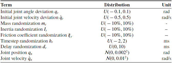
To enhance the generalization ability of the trained policy, domain randomization is applied during the RL process. This approach ensures that the control strategy maintains balance across a range of dynamic models. Parameters such as the mass and inertia of the links, along with simulation factors like sensor noise, initial joint angles, and velocities, as well as timestep and delay, are randomized. The specific details are shown in Figure 3.
At the beginning of each episode, a set of dynamic parameters for the UTPR is randomly sampled from predefined probability distributions and remains fixed throughout the episode. Meanwhile, the system state is initialized based on randomized initial joint angles and velocities drawn from specified distributions. For each timestep within the episode, simulation environment parameters such as timestep size, simulation delay, and sensor noise, as well as motor model parameters, are randomized within predefined ranges.
The distributions of the domain randomization process are provided in Table II. In this context, the notation
 $U(a, b)$
denotes a uniform distribution across the interval
 $(a, b)$
, and
 $\mathcal{N}(\mu , \sigma ^2)$
represents a Gaussian distribution with mean
 $\mu$
and variance
 $\sigma ^2$
. The mass, inertial, and friction coefficient noise are scaled proportionally to their default values, while the other randomization and noise are added directly.
Domain randomization parameters.

Diagram for the sim-to-real strategy.

By integrating motor friction modeling and domain randomization, this study takes into account a broader range of real-world factors that can affect control performance. This approach enhances the feasibility of transferring the RL controller from simulation to the real world and lays a solid foundation for its practical deployment.
4.2. Performance-guided adaptive CL
Although motor model identification and domain randomization greatly facilitate the sim-to-real transfer, the introduction of numerous randomized factors also significantly increases the training difficulty. To ensure the successful learning of a balance control policy suitable for real-world deployment under such conditions, this study further proposes an adaptive CL strategy.
4.2.1. Curriculum stage design
Given the absence of clear quantitative criteria for defining difficulty levels and sequencing among the factors listed in Table II, this study adopts a performance-guided adaptive CL approach. Instead of manually decomposing the task, the training difficulty is dynamically adjusted based on the agent’s current performance. At the start of training, the agent encounters the simplest task setting, where none of the randomized factors are active. As the agent successfully masters this initial task, the factors from Table II are gradually introduced and their intensities proportionally increased. This progression allows the agent to continuously adapt to an environment of rising complexity.
Practically, the difficulty level is controlled by the current training stage
 $S$
, with the magnitude or range of each randomization factor increasing linearly with
 $S$
according to the formula:
 \begin{equation} d(F_i,S) = d_{\text{max}}(F_i) \times \frac {S}{S_{\text{max}}},\quad i\in \{q_r, \dot {q}_r, m_r, I_r, \boldsymbol{\xi }_r, h_r, d_r, q_n, \dot {q}_n\} \end{equation}
Here,
 $d_{\text{max}}(F_i)$
represents the maximum intensity of a given factor
 $F_{i\in \{q_r, \dot {q}_r, m_r, I_r, \boldsymbol{\xi }_r, h_r, d_r, q_n, \dot {q}_n\}}$
, with specific values consistent with those in Table II.
 $S_{\text{max}}$
denotes the maximum number of training stages. The progression of training stages depends on the agent’s balance performance. Specifically, when the UTPR successfully completes the balance task for
 $N_s$
consecutive episodes, the task difficulty advances to the next stage
 $S+1$
, until
 $S$
reaches
 $S_{\text{max}}$
, beyond which it no longer increases.
4.2.2. Linear adaptive CL
The detailed process of linear adaptive CL is shown in Figure 4. Adaptivity is reflected in the fact that task difficulty is not predefined, but rather automatically adjusted based on the agent’s learning performance. This adaptive characteristic allows the learning process to flexibly handle complex randomized environments and avoids the negative effects of introducing complex factors too early or too late.
Flowchart of adaptive curriculum learning.

To evaluate the effectiveness of the proposed linear adaptive CL strategy, this study compares the CSAC-QI training performance under different values of
 $S_{\text{max}}$
, including 0, 1, 2, 5, and 10. Figure 5 shows the learning curves for the five different values of
 $S_{\text{max}}$
, with
 $N_s$
set to 10. When
 $S_{\text{max}}$
= 0, the agent directly faces the most complex task environment and fails to learn any policy, with the total reward per episode remaining at a very low level. When
 $S_{\text{max}}$
= 1, the agent transitions directly from the simplest task to the most difficult one, leading to training failure. For
 $S_{\text{max}}$
= 2, 5, and 10, since the final task is divided into multiple stages, the agent successfully learns a balance control policy in complex environments. Among these,
 $S_{\text{max}} = 10$
achieves the smoothest progression in task difficulty due to the highest number of stages, leading to the best training outcome. Its performance is significantly better than that of
 $S_{\text{max}} = 2$
and marginally better than that of
 $S_{\text{max}} = 5$
.
Learning curves for five different values of
 $S_{\text{max}}$
.

The results above indicate that as
 $S_{\text{max}}$
increases, the convergence speed and stability of the reward also improve, demonstrating the effectiveness of adaptive CL. However, when
 $S_{\text{max}}$
exceeds 5, further increasing the number of stages yields diminishing improvements in training performance. Therefore, in this study,
 $S_{\text{max}}$
= 10 is chosen as an ideal setting. The linear adaptive CL strategy achieves a smooth transition from no domain randomization to full domain randomization by gradually increasing task difficulty, thereby reducing the difficulty of policy learning and the risk of training failure.
5. Experiment
This section verified the performance of the proposed CSAC-QI control strategy for the UTPR’s balance control. The simulation results demonstrate the system’s ability to handle various tasks, such as recovering from joint deviations, controlling the end-effector position, and maintaining balance despite randomization and noise in the simulation platform. The results of real-world experiment show the basic balance capability tested after direct deployment on the UTPR prototype, STANDER.
5.1. Experiment setup
All simulation experiments were conducted on a desktop running Ubuntu 22.04, equipped with an Intel i9-9900K CPU and an NVIDIA GeForce 2,080 Ti GPU. The simulation diagram is shown in Figure 6. The experiments utilized a custom-developed C++ simulation platform, Sire [18], which is based on the Aris dynamics library [25]. The Sire platform has been thoroughly validated, yielding simulation results nearly identical to those of MuJoCo [Reference Todorov, Erez and Tassa39]. Furthermore, Sire offered highly customizable domain randomization and motor friction calculation features, which were crucial for this study. The RL environment, based on the Gymnasium [Reference Towers, Kwiatkowski, Terry, Balis, De Cola, Deleu, Goulao, Kallinteris, Krimmel and KG40] and Sire Python/C++ interface, enabled interaction between the UTPR in the simulation and the RL algorithm or agent. The simulation environment modeled the UTPR with dynamic parameters consistent with those in Table III.
Dynamic parameters in the model of the UTPR.

The simulation was built upon the dynamics equation presented in Eq. (1) and employed the semi-implicit Euler method for numerical integration with a timestep of 1 ms. Consistent with the actual characteristics of the UTPR robot, the maximum joint torque
 $\tau _{max}$
was set to 10
 $\text{N}\cdot \text{m}$
, and each joint’s position constraints were defined as
 $-\pi /2\lt q_1\lt \pi /2$
,
 $-2\lt q_2,q_3\lt 2$
[rad]. Table IV provided an overview of the coefficients used in the reward function, including the weights and scaling factors associated with each component.
Coefficients of reward function with integral term.

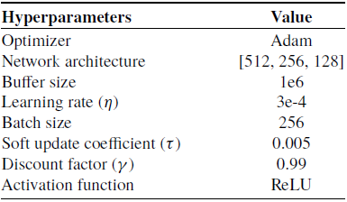
In the simulation experiment, each timestep was configured to 25 ms (with a frequency of 40 Hz), with the maximum simulation runtime set to 10 s, resulting in a maximum of 400 steps. The control policy was trained using the SAC algorithm, with the key hyperparameters detailed in Table V.
Hyperparameters of SAC algorithm.

Diagram for the simulation experiment setup.

To validate the efficacy of the proposed method, three tasks were formulated, each corresponding to different aspects of the control strategy: precision, adaptability, and robustness.
-
1. Task 1: balance control at the upright position with random initial joint angle and velocity deviations;
-
2. Task 2: balance control at various targeted end-effector positions;
-
3. Task 3: balance control with dynamic randomization, sensor noise, and external disturbances.
In Task 1 and Task 2, the experiments only considered the control performance under ideal simulation conditions. In Task 3, due to the incorporation of randomization, the policy was required to maintain balance and stability in 10 consecutive trials to be considered robust under the specified level of randomization or noise.
5.2. Simulation experiments
For comparison, the performance of five control strategies was evaluated: CSAC with quadratic reward (CSAC-QUA), CSAC with absolute value reward (CSAC-ABS), CSAC with quadratic reward and an integral term (CSAC-QI), linear quadratic regulator (LQR), and model predictive control (MPC). LQR and MPC served as baseline algorithms for comparison, with a control frequency of 100 Hz. The experimental results were as follows:
5.2.1. Task 1: Initial joint deviation recovery
Figure 7 illustrates the time-varying joint angles of the UTPR under five control strategies as it recovered from an initial angle of
 $[0.014, 0, 0]$
rad (
 $\approx [0.8, 0, 0]$
deg, which was close to the maximum deviations that the primary MPC could tolerate) in an ideal scenario.
The experimental results of five control methods under task 1. (a) Angle of the first joint changes with time; (b) Angle of the second joint changes with time; (c) Angle of the third joint changes with time.

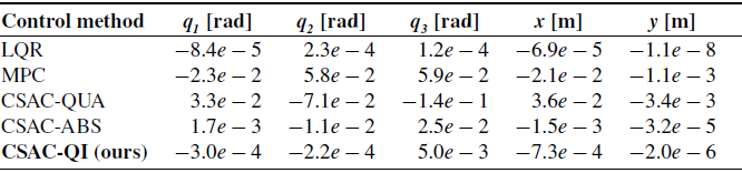
From the joint angle curves, the CSAC methods demonstrated faster control response. According to the steady-state error results in Table VI, LQR demonstrated the smallest errors, followed by CSAC-QI, while CSAC-QUA exhibited significantly larger errors.
Error of joint angles and end-effector at the end of an episode (
 $t=10$
s).

To evaluate the performance of different control strategies to handle initial joint deviations, both the maximum allowable joint position deviation
 $q_1|_{t=0}$
and joint velocity deviation
 $\dot {q}_1|_{t=0}$
were examined.
As summarized in Table VII, CSAC-QI demonstrated significantly higher tolerance to initial joint deviations compared to LQR and MPC.
Tolerance ranges for initial angle and angular velocity deviations at the underactuated joint under different control methods.

Specifically, CSAC-QI successfully handled initial position deviation within a range of approximately
 $[-0.1281, 0.1298]$
rad and initial velocity deviation within approximately
 $[-0.443, 0.463]$
rad/s.
5.2.2. Task 2: Target end-effector position control
The purpose of this experiment is to test the balance control capability of the UTPR in states beyond the vertical upright position, as well as its performance in accurately controlling the end-effector position. Due to the highly nonlinear nature of the UTPR, baseline control methods that rely on linearization assumptions are no longer applicable when balancing in non-vertical states, making it more challenging to achieve stable balance control under such conditions.
To evaluate the performance of the control strategy in reaching specified end-effector target positions, two representative target points, [0.2, 0.4] m and [0.1, 0.5] m, were selected, corresponding to two different control scenarios. The UTPR first computed the joint angles corresponding to each target position by solving the inverse kinematics Eq. (7), and then learned a balance control policy around the target joint configurations.
For the target point [0.2, 0.4] m, the inverse kinematics of the UTPR yields only one solution,
 $\boldsymbol{q}^{*}$
= [0.43003, −0.88035, −0.92856]
 $^T$
rad. The simulation results are shown in Figure 8, where the UTPR reaches the desired state corresponding to the target within approximately 1 s and maintains a stable balanced posture thereafter.
Simulation results of reaching target at [0.2, 0.4] m. (a) Joint torques of the UTPR; (b) Joint angles of the UTPR; (c) Joint angular velocities of the UTPR; (d) Position of the end-effector of the UTPR.

For the target point [0.1, 0.5] m, the inverse kinematics of the UTPR yields two solutions. By numerical methods, the two inverse solutions are obtained as
 $\boldsymbol{q}^{(1)}$
= [0.50227, −1.36818, 0.64436]
 $^T$
rad and
 $\boldsymbol{q}^{(2)}$
= [−0.10736, 0.53134, −1.35839]
 $^T$
rad. The simulation results corresponding to these two inverse solutions are shown in Figures 9 and 10, respectively.
Simulation results of reaching target at [0.1, 0.5] m (first inverse solution). (a) Joint torques of the UTPR; (b) Joint angles of the UTPR; (c) Joint angular velocities of the UTPR; (d) Position of the end-effector of the UTPR.

In both cases, CSAC-QI successfully learns balance control policies and achieves stable balancing at the target positions within 1 s. In contrast, the baseline LQR and MPC methods, due to their reliance on linearization assumptions and the absence of additional balance control designs, are unable to accomplish the target end-effector position control task, further highlighting the superior adaptability of the RL-based approach.
The steady-state errors between the end-effector and the target points for the CSAC algorithm without the QI-form reward function and CSAC-QI are summarized in Table VIII. The table presents the error values in both the
 $x$
and
 $y$
directions for two target points. The CSAC-QI method demonstrated significantly smaller errors compared to CSAC, indicating the QI-form reward improved performance in achieving more accurate end-effector positions at the target points.
Error between the end-effector and the target point at
 $t=5$
s.

Simulation results of reaching target at [0.1, 0.5] m (second inverse solution). (a) Joint torques of the UTPR; (b) Joint angles of the UTPR; (c) Joint angular velocities of the UTPR; (d) Position of the end-effector of the UTPR.

5.2.3. Task 3: Robustness in non-ideal environments
To evaluate the robustness of the control strategies, Figure 11 presents the performance of CSAC-QI, LQR, and MPC in recovering the UTPR from an initial angle of
 $[0.014,0,0]$
rad to the upright position. In this scenario, the model was subjected to a
 $1$
% randomization (the maximum level for primary MPC) of dynamic parameters, with joint position and velocity noise added at levels of
 $\mathcal{N}(0, 0.002^2)$
rad and
 $\mathcal{N}(0, 0.01^2)$
rad/s, respectively. Additionally, at
 $t=5$
s, an external force of
 $1.5$
n was applied in the positive x-direction to the third link of the UTPR for
 $0.1$
s.
The experimental results of three control methods under task 3. (a) Angle of the first joint changes with time; (b) Angle of the second joint changes with time; (c) Angle of the third joint changes with time. When
 $t=5$
s, an external force
 $f_{ext}=1.5$
N for
 $0.1$
s is applied.

Figure 12 illustrates the balancing ability of the proposed CSAC-QI method under extreme conditions. The model was subjected to
 $10$
% dynamic parameter randomization, along with joint position and velocity noise levels of
 $\mathcal{N}(0, 0.004^2)$
rad and
 $\mathcal{N}(0, 0.02^2)$
rad/s, respectively. At
 $t=5$
s, the external force was increased to
 $7$
n in the positive x-direction on the third link of the UTPR. The UTPR successfully recovered from an initial state of
 $[0.1, 0, 0]$
rad (
 $\approx [5.7, 0, 0]$
deg) to the upright position, a result that primary model-based control strategies struggled to achieve.
Simulation results of CSAC-QI under task 3. (a) Joint torques of the UTPR; (b) Joint angles of the UTPR; (c) Joint angular velocities of the UTPR; (d) Position of the end-effector of the UTPR. When
 $t=5$
s, an external force
 $f_{ext}=7$
N for
 $0.1$
s is applied.

In Table IX, the CSAC-QI method demonstrated the highest robustness, handling dynamic randomization up to
 $18.5$
% and managing sensor noise levels of
 $0.051$
rad in joint position and
 $0.282$
rad/s in joint velocity without falling down.
Performance metrics of control methods (consider each factor individually).

5.3. Real-world experiment
In the sim-to-real experiment, the policy network trained in Task 3 was directly deployed onto the UTPR prototype, STANDER, for real execution without any additional tuning or adaptation. The forward inference was conducted using LibTorch [1] (the C++ interface of PyTorch), which enabled the efficient real-time deployment of the trained model on the physical system. The trajectory of UTPR in the real world is shown in Figures 13, and 14 shows the balance process of the STANDER prototype.
Real-world sim-to-real experimental results. (a) Joint torques of the STANDER prototype; (b) Joint angles of the prototype; (c) Joint angular velocities of the prototype; (d) Position of the end-effector of the prototype. Only the results for the first
 $10$
Seconds were shown in the image, and detailed data and video can be found in the supplementary materials.

Control processes on the simulation and physical platforms.

Despite the UTPR prototype’s early stage of development and the absence of advanced sensor filtering algorithms, the system was still able to maintain balance for at least
 $60$
Seconds, with the potential for longer durations if given extended testing periods. This result demonstrated the robustness of the learned control policy and its generalization capability from simulation to real-world application.
5.4. Comparative studies and analysis
To further validate our design choices and compare our proposed method against common alternatives, as suggested during the review process, we conducted two additional sets of comparative experiments in the simulation environment.
5.4.1. Analysis of reward function shape
To investigate the impact of the reward function’s shape on learning performance, we conducted a comparative analysis between the exponential quadratic (L2) reward used in CSAC-QI and a reward function based on Huber loss (with
 $\delta = 0.05$
rad). We evaluated their performance across three levels of task difficulty, defined by the range of initial joint angle deviations. The success rate, defined as the percentage of episodes where the agent maintained balance for the full duration, was used as the primary performance metric.
The results, summarized in Table X, reveal a complex, non-linear relationship between task difficulty and the optimal reward function shape.
Success rates of L2 vs. Huber reward under different initial deviation ranges.

A non-monotonic performance trend was observed. In the easy task, the Huber loss reward held a slight advantage, likely because its more forgiving penalty for moderate errors encouraged effective exploration. However, as task difficulty increased to the medium level (
 $[-0.2, 0.2]$
rad), which represents a critical range for robust balancing, the L2 reward demonstrated a clear advantage. This suggests that the harsher penalty of the L2 loss for larger deviations is crucial for learning effective recovery strategies in this challenging regime.
Interestingly, as the task became extremely hard (
 $[-0.3, 0.3]$
rad), the Huber loss reward once again showed a slight advantage. A plausible explanation is the potential “discouragement effect” of the L2 reward: the extreme penalties for frequent large errors in this regime might suppress exploration, whereas the linear penalty of Huber loss provides a more consistent gradient. Despite this, the L2 form proved superior in the critical medium-difficulty range and, most importantly, the policy trained with L2 loss successfully transferred to the real world, validating its suitability for the target control task.
5.4.2. Performance of hybrid RL + PID strategy
To evaluate the performance of our end-to-end approach against hybrid control strategies, we implemented and tested a representative RL + PID controller in our simulation environment. In this setup, the RL agent outputs target position setpoints, which are then tracked by a low-level PD controller to generate motor torques, following the formulation in Eqs. (18) and (19). For this simulation experiment, the PD controller gains were set to
 $k_p=30$
and
 $k_d=1$
to ensure stable tracking performance.
The simulation results, presented in Figure 15, indicate that the hybrid RL + PID method is capable of learning a stable balancing policy within the simulation environment. The agent successfully learned to stabilize the UTPR from initial deviations, showing convergence similar to the end-to-end method. Although some overshoot is observed during the transient phase, the system eventually converges to the stable upright position.
Simulation performance of the hybrid RL + PID controller on the balancing task. The curves show the joint angles of the UTPR successfully recovering from an initial deviation of
 $\boldsymbol{q}=[0.1, 0, 0]$
rad to a stable upright position.

However, as noted in the methodology design, this approach relies on the assumption that the low-level PID controller can perfectly track the desired trajectories. In our sim-to-real experiments, the policy learned by this hybrid method failed to generalize to the physical prototype due to the reality gap in actuator dynamics and system delays. This contrast highlights the challenge of transferring non-end-to-end policies and underscores the robustness of our proposed end-to-end CSAC-QI strategy, which directly learns torque commands to cope with real-world dynamics.
6. Discussion and conclusion
In the basic Task 1, the joint angle trajectory in Figure 7 demonstrates that the CSAC method reacts faster in recovering from initial joint deviations. Among the CSAC methods with different reward functions, Table VI shows that the CSAC-QI method reduces the error by at least one order of magnitude, achieving results closest to those of LQR. Compared to primary LQR and MPC, the CSAC-QI method outperforms in handling larger initial joint deviations, increasing the range of initial joint angles by at least 447.4% and the range of initial angular velocities by at least 334.3%, as shown in Table VII. In Task 2, the model-free control methods demonstrate excellent target control of the end-effector without additional design. CSAC-QI significantly improves the accuracy of end-effector position control, also achieving smaller errors compared to the CSAC, as shown in Table VIII. These two tasks indicate that incorporating the QI-term in the reward function enhances the algorithm’s performance in achieving precise joint position control for underactuated systems like the UTPR.
In Task 3, by progressively decomposing the task into increasingly challenging subtasks, CSAC successfully guided the robot to converge to a stable reward around the 1400th training episode. This highlights the importance of task decomposition and CL in accelerating convergence, improving efficiency, and reducing the risk of failure during training. As shown in Table IX, compared to the primary model-based method, the CSAC-QI method improves tolerance to dynamic parameter randomization by at least 255.8%, and increases tolerance to joint position noise by at least 155.0% and to joint velocity noise by at least 115.2%. Moreover, in Figure 12, the UTPR successfully maintained balance under extreme randomization, noise, and external disturbances, demonstrating the strong robustness of the CSAC strategy.
Although the CSAC-QI method requires high computational resources during training, once training is complete, the controller requires less than
 $1$
ms of computation per timestep and can be effectively deployed in real-time systems with computational constraints. The experimental results present in Figures 13 and 14 validate the ability of the proposed CSAC-QI method to generalize to the physical UTPR prototype. While the UTPR prototype is still not ideal, the system maintains balance for at least
 $60$
Seconds under real-world conditions. The results highlight the method’s capacity to bridge the sim-to-real gap in underactuated robotic systems, even under non-idealized environmental and hardware constraints.
This paper demonstrates the effectiveness and robustness of the proposed CSAC-QI strategy in controlling the balance of the UTPR. By employing a CL approach to decompose the task into increasingly complex stages, convergence is accelerated and the risk of failure is reduced. To address the issue of inaccurate control by RL controllers in underactuated systems, a penalty term for accumulated joint angle errors is added to the reward function, significantly reducing steady-state errors. Simulation experiments show that CSAC-QI outperforms in handling large initial joint deviations and achieving target end-effector position control. Moreover, CSAC-QI exhibits exceptional robustness under significant dynamic randomization, sensor noise, and external disturbances. To bridge the gap between simulation and reality, domain randomization and motor friction identification provide support for the direct deployment of the control strategy on the UTPR prototype. The UTPR prototype, controlled by the policy network trained using the CSAC-QI method, maintaining balance for at least
 $60$
Seconds under real-world conditions. The sim-to-real experimental results reflect the strong robustness of the proposed controller in underactuated systems. Future research will focus on refining the UTPR prototype and further testing the precise and stable control performance of the CSAC-QI strategy in reality to verify its superiority.
Supplementary material
The supplementary material for this article can be found at https://doi.org/10.1017/S0263574726103282.
Author contributions
Y.F., J.G. and Y.P. conceived and designed the study. Y.F., J.G. and Y.P. developed the methodology. Y.F. and J.G. wrote the software and built the hardware. Y.F., J.G., and D.L. validated the results. Y.F. and D.L. performed the formal analysis. Y.F. and J.G. conducted the investigation. Y.P. provided the resources. Y.F. and J.G. collected the data. Y.F. prepared the original draft of the manuscript. Y.F. and J.G. revised the manuscript. J.C., L.H., Y.Q. and Y.P. reviewed and edited the manuscript. Y.F. created the visualizations. Y.P. supervised the project. Y.P. managed the project and acquired funding. All authors have read and agreed to the published version of the manuscript.
Financial support
This research was funded by the National Key R&D Program of China under Grant 2022YFB4701200, the Science, Technology and Innovation Commission of Shenzhen Municipality under Grant SGDX20220530110804030, JCYJ20220818100417038, and the National Key Laboratory of Aerospace Mechanism under Grant 2024ASM-KFZY01.
Competing interests
The authors declare no conflicts of interest.
Ethical approval
Not applicable.