


1. Introduction
Automatically assessing the quality of buildings is a significant concern of researchers in the field of construction robotics. This evaluation includes crack, evenness, alignment, and hollows. In the field of intelligent perception, numerous autonomous robots are utilized, including wheeled [Reference Yao, Shi, Xu, Lyu, Qiang, Zhu, Ding and Jia1] and legged robots [Reference Seeni, Schäfer and Hirzinger2, Reference Yao, Xue, Wang, Yuan, Zhu, Ding and Jia3]. However, wheeled robots are commonly utilized in construction robotics due to their superior stability during movement. By implementing sensors capable of capturing corresponding defect information, robots can assist workers in resolving these issues. Nonetheless, the detection results of individual sensors are only applicable to themselves and cannot be integrated into the robot system, resulting in the inability to accurately obtain the location and quantity of defects [Reference Yu, Man, Wang, Shen, Hong, Zhang and Zhong4]. Fig. 1 illustrates the construction quality inspection robot we have developed, equipped with a structured light camera(SLC), a thermal camera, and a LiDAR. The SLC is capable of capturing the environmental texture and conducting 3D measurements to effectively detect cracks and flatness. The thermal camera, accurately connected with the SLC through location holes, detects hollow relying on variances in the thermal capacity of building materials. Meanwhile, LiDARs can perceive the indoor environment and generate a prior map for construction robots. Thus, it is essential to appropriately align these sensor data for the construction quality inspection robot by LiDAR-SLC extrinsic calibration.
The total workflow of the quality inspection robot system.

Extrinsic calibration, which refers to the method of aligning different types of data, entails processing data obtained from individual sensors to estimate the relative position and orientation among them. Generally, the calibration procedure involves three essential steps: (1) feature extraction, (2) matching strategies, and (3) optimization methods. Depending on the method of feature extraction, calibration can be classified into two categories: target-based methods and target-less methods. Based on the process of feature extraction, calibration can be classified into two categories: target-less and target-based methods. The primary contrast between the two methods lies in the requirement of a calibration board. Features for the non-target method are gathered from the surrounding environment, whereas the calibration board-based method requires artificial setup to extract reference features.
1.1. Target-less methods
Target-less methods aim to incorporate a range of techniques to extract feature information from the environment and establish the appropriate sensor relationships. The available extrinsic parameters can be determined by projecting two types of features onto the same coordinate system and by minimizing the error between them.
Edge extraction is a popular method for extrinsic calibration due to its simplicity. It combines gradient changes of image pixels with the discontinuity or continuity of the LiDAR point cloud [Reference Zhu, Zheng, Yuan, Huang and Hong5]. Zhang et al. extracted pole line characteristics from images and point clouds and determined the appropriate extrinsic parameters by developing a synthesized cost function in both horizontal and vertical directions [Reference Zhang, Zhu, Guo, Li and Liu6]. They obtained line features from the point cloud and used an adaptive optimization method to calculate the calibration results. Additionally, researchers also explored the use of sensor intensity as a feature. For example, [Reference Zhao, Wang and Tsai7] used the statistical similarity of object surface intensities as feature information and obtained optimal extrinsic parameters for cameras and 3D LiDARs. However, the accuracy of intensity information may not be guaranteed due to environmental factors such as illumination.
Machine learning is a powerful approach for problem-solving due to its capability of handling diverse and numerous features, as well as the continuous development of computer technologies. RegNet [Reference Schneider, Piewak, Stiller and Franke8] and CalibNet [Reference Iyer, Ram, Murthy and Krishna9] are two prominent techniques for joint calibration of LiDARs and camera. RegNet can generate annotated data automatically and use the iterative refinement calibration method to cope with large variances. Nevertheless, this process is time-consuming, and the feature extraction-matching ability is restricted. Conversely, CalibNet incorporated a corresponding loss function into the network to accommodate the point cloud geometry. However, the devised training strategy limited CalibNet’s further development. To address these limitations, LCCNet [Reference Lv, Wang, Dou, Ye and Wang10] was proposed and performed exceptionally well. Additionally, features that are semantically segmented from images and point clouds can be utilized as feature points. Wang et al. [Reference Wang, Nobuhara, Nakamura and Sakurada11] utilized the centroid of semantics with identical labels from image and point cloud data as reference points for the sensors; however, the efficacy of this approach heavily depends on the semantic segmentation outcomes.
1.2. Target-based methods
Target-based methods artificially define features that units such as cameras and LiDARs can recognize as reference points. These marks are utilized to associate the sensors, which subsequently transforms the calibration of extrinsic parameters into a Perspective-n-Points(PnP) [Reference Lepetit, Moreno-Noguer and Fua12] or an optimized problem [Reference Kummerle, Grisetti, Strasdat, Konolige and Burgard13].
1.2.1 Single chessboard
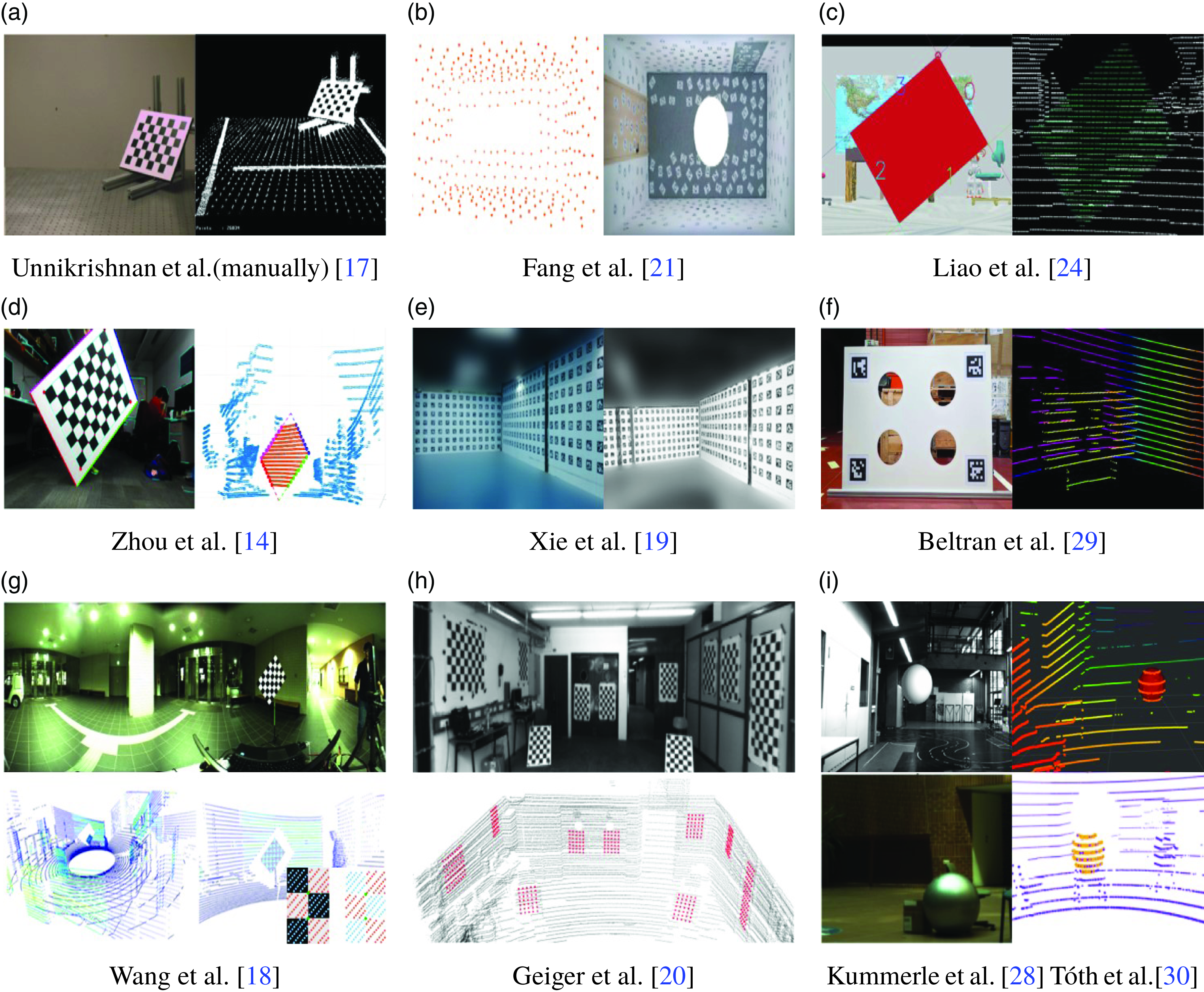
One simple option to obtain a feasible solution is to directly use a single chessboard and employ its geometric constraints [Reference Zhou, Li and Kaess14] or intensity [Reference Koo, Kang, Jang and Doh15]. Q. Zhang et al. [Reference Zhang and Pless16] were pioneers who employed a planar checkerboard for camera and 2D LiDAR calibration, taking into account plane-line correspondences as constraints for the extrinsic parameters. However, this technique fails to achieve proper calibration accuracy because a limited number of constraints from single-frame data are insufficient for calibration, and the unstable accumulation trajectory for multi-frame data produces uncertain results. A chessboard-based calibration algorithm for cameras and 3D LiDARs is presented in Fig. 2(a). They acquire coarse parameters through plane-plane correspondences and employ point-plane constraints to enhance accuracy [Reference Unnikrishnan and Hebert17]. This method entails separate stages of data collection and processing, which requires an continuous user interface throughout the entire process. W. Wang et al. [Reference Wang, Sakurada and Kawaguchi18] utilized the correlation between the intensity of the point cloud and the color of the checkerboard to identify feature points from the detected corner points, as depicted in Fig. 2(g). However, the extrinsic calibration of the panoramic camera and 3D LiDAR sensors is unstable using this approach as the intensity is affected by factors other than color.
1.2.2 Multiple chessboards or markers
Affixing multiple chessboards or markers to an indoor setting is an extension of the calibration board technique. The placement of multiple chessboards or markers [Reference Xie, Shao, Guli, Li and Wang19] within an indoor setting is an extension of the calibration board method. While these techniques require merely a single scene shot, they entail manually attaching the chessboards within the room before calibration can take place. In Fig. 2(h), multiple cameras were associated with 3D range sensors utilizing the normal vectors of multiple affixed checkerboard patterns as features, resulting in acceptable outcomes in a single shot [Reference Geiger, Moosmann, Car and Schuster20]. The panoramic infrastructure, as shown in Fig. 2(b), localizes and connects sensors using the pasted marks and room corners to achieve single-shot calibration [Reference Fang, Ding, Dong, Li, Zhu and Tan21]. Though these methods exhibit simplicity and user-friendliness, their preparation involves significant labor and lacks flexibility. These limitations can make it challenging for dynamic systems that require frequent recalibration or when there are changes in the environment.
1.2.3 Novel calibration board
Various calibration boards with novel shapes have been proposed to generate more robust reference points, such as triangles [Reference Debattisti, Mazzei and Panciroli22], polygons [Reference Park, Yun, Won, Cho, Um and Sim23, Reference Liao, Chen, Liu, Wang and Liu24], circles [Reference Deng, Xiong, Yin and Shan25, Reference Fremont, Rodriguez F. and Bonnifait26], and spheres [Reference Pereira, Silva, Santos and Dias27, Reference Kummerle, Kuhner and Lauer28]. These designs provide distinguishable characteristics for various sensors. For example, a calibration method for binocular and monocular cameras [Reference Beltran, Guindel, de la Escalera and Garcia29], as well as LiDARs, was proposed using a board with four circular holes and markers, as depicted in Fig. 2(f). The appropriate arrangement of the calibration board is crucial for achieving accurate results with this method. T. Tóth et al. [Reference Tóth, Pusztai and Hajder30] employed spherical objects as targets and synchronized the monocular camera and LiDARs with reference points derived from the fitting of point cloud, as shown in Fig. 2(i). Nonetheless, setting up calibration scenes can be a challenging task and may not guarantee high accuracy. For simpler tasks that are not highly demanding in terms of precision, researchers may manually select feature points [Reference Unnikrishnan and Hebert17, Reference Dhall, Chelani, Radhakrishnan and Krishna31]. Although feature points selected manually by these methods are robust, they are still susceptible to human error and lack complete automation.
Classification of target-based methods according to different types of calibration board. Single chessboard: (a) (d) (g); Multiple chessboard or marks: (b) (e) (h); Novel shaped boards: (c) (f) (i). Top/left: 2D image; bottom/right: 3D point cloud.
1.3. Challenges
SLCs are an excellent alternative for quality inspection, as they can provide accurate and detailed information over a range of areas. Therefore, we can effectively utilize this specific attribute to address the extrinsic calibration problem within LiDAR-structured light camera systems. Nevertheless, current calibration techniques mainly focus on conventional cameras, and adapting them to SLCs and LiDARs can cause various issues:
1.3.1 Low-textured environments
Although environmental feature association [Reference Zhu, Zheng, Yuan, Huang and Hong5, Reference Zhang, Zhu, Guo, Li and Liu6] is a convenient method for aligning the cameras and LiDARs, it may not be applicable for SLCs due to low-textured environments and the poor anti-interference ability of the cameras. Consequently, the implementation of existing target-less calibration algorithms based on environmental features, including learning-based methods, may lead to ineffective alignment results.
1.3.2 Human intervention
To achieve accurate and efficient calibration, a single chessboard and its extended methods are insufficient due to significant human intervention, such as attaching marks [Reference Fang, Ding, Dong, Li, Zhu and Tan21] or setting up multiple objectives [Reference Deng, Xiong, Yin and Shan25, Reference Tóth, Pusztai and Hajder30], which renders the calibration process difficult to implement.
1.3.3 Characteristics of SLCs
SLCs are an ideal choice for building quality inspection as they provide dense point cloud information for detecting minor defects in construction. However, SLCs require relatively static conditions in order to successfully capture accurate point clouds. Therefore, employing multiple poses of calibration boards to enhance the accuracy of extrinsic calibration would be an exceedingly laborious process.
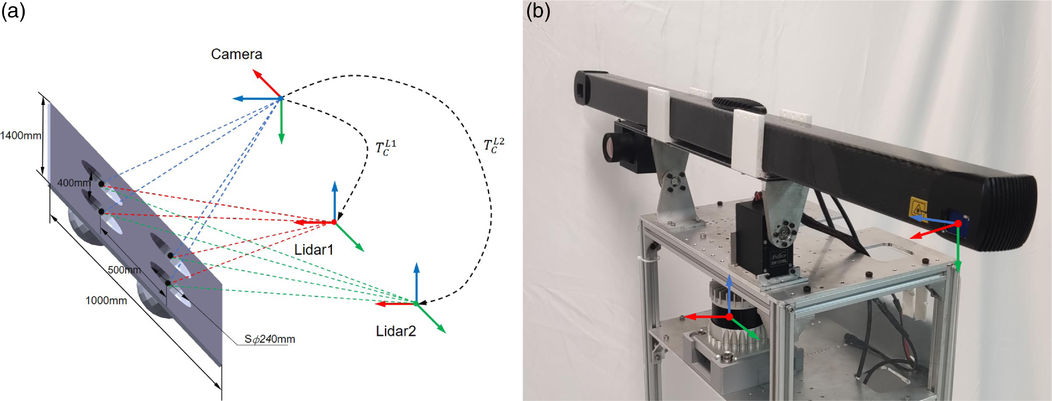
(a) The customized calibration board is placed in the overlapped view of two sensors to provide additional reference points for each sensor pair. (b)The real-world SLC-LiDAR sensors.
1.4. Contributions
Considering the above challenges, we propose a novel calibration method utilizing a custom hemispherical board to spatially align the LiDAR-SLC systems. The evenly distributed centers of the hemispheres on the calibration board serve as reference points for associating the two sensors, as shown in Fig. 3. Meanwhile, the reference points are adjusted to ensure a more precise joint through point-plane and point-point constraints derived from the calibration board. Instead of directly employing Iterative Closest Points (ICP) approaches, registration and optimization strategies are employed separately to estimate extrinsic parameters quickly. Specifically, our contributions can be summarized as follows:
-
1. We propose an automatic method for extracting feature points to calibrate SLCs and LiDARs. This method provides superior anti-interference capability as the feature points are derived by the fitted sphere centers, rather than corners or boundary points.
-
2. We introduce an enhanced calibration board with geometric constraints that improves the accuracy of extracting feature points. Additionally, the calibration can be completed with just a single board position, minimizing human intervention as much as possible.
-
3. We validated the advantages of proposed calibration algorithm through a comprehensive series of simulations and real experiments, being suitable for construction robotics applications.
The remainder of this manuscript is organized as follows: Section 2 describes the proposed calibration method in detail. In order to validate the accuracy and robustness of the algorithm, we conducted a set of simulations and real-world experiments in Section 3. Finally, Section 4 presents a summary of the research conducted in this paper, as well as a prospective analysis of future research.
2. Methodology
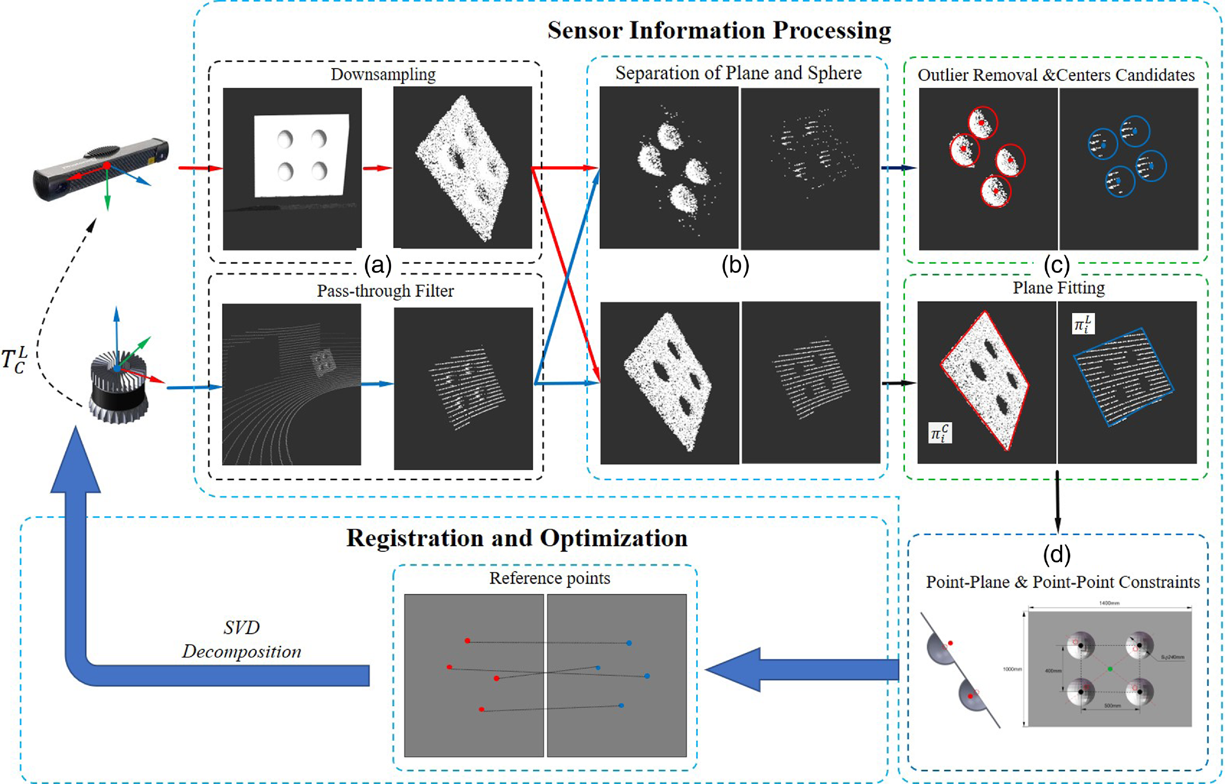
Our calibration approach comprises two main parts: (i) sensor information processing and (ii) registration and optimization. The former step involves collecting raw data from the Structured Light Cameras(SLCs) and LiDARs, and extracting the designated features through several processing steps. The latter consists of aligning the extracted reference points and performing an appropriate optimization process to determine the optimal extrinsic parameters. The pipeline of the calibration methodology is illustrated in Fig. 4: The sensor data processing can be roughly divided into four stages: downsampling and filtering, plane and spherical segmentation, outlier removal, and candidate point optimization and adjustment. These stages provide effective reference points for the subsequent optimization.
The pipeline of our calibration method.
2.1. Problems formulation and assumption
The extrinsic calibration problem involves finding the relative position and orientation of a camera and a LiDAR sensor mounted on a common platform. This can be achieved by estimating a transformation matrix
 $T_{L}^{C}$
, which aligns the LiDAR and camera coordinate frames. The goal of the calibration process is to minimize the distance between the corresponding points in the two frames.
The four spherical centers, derived from our custom calibration board as shown in Fig. 3(a), serve as the reference points. Our calibration board is a
 $1000\times 1400 mm$
rectangle with four hemispheres distributed symmetrically at a position of
 $400\times 500 mm$
. These hemispheres, which have a diameter of 240 mm, efficiently gather information from the sensor and enable accurate fitting of the reference points.
 $p_{i}^{C}$
and
 $p_{i}^{L}$
are the reference points, where
 $C$
and
 $L$
denote the camera and LiDAR’s coordinate system. The extrinsic calibration problem can be described by the following formula:
 \begin{equation} P^{C} = R_{L}^{C}P^{L} + t_{L}^{C} \end{equation}
where
 $T_{L}^{C}=\left [R_{L}^{C};\; t_{L}^{C} \right ]$
,
 $P^{C}= \left \{ p_{1}^{C}, p_{2}^{C},\cdots \right \}$
,
 $P^{L}= \left \{ p_{1}^{L}, p_{2}^{L},\cdots \right \}$
, and
 $R_{L}^{C}$
and
 $t_{L}^{C}$
are the rotation and translation parameters that describe the relative pose of the LiDAR from the camera frame. SLCs capture three-dimensional geometric information, including points, shapes, surface colors, and other attributes in space. These data can be represented in three modalities: RGB-texture, Depth-map, and Point cloud. Here, high-precision point cloud information is chosen as input, eliminating the need to consider the camera’s intrinsic parameters, which facilitates subsequent optimization processes.
To solve for
 $T_{L}^{C}$
, we need to find the values of
 $R_{L}^{C}$
and
 $t_{L}^{C}$
that minimize the distance between the corresponding reference points in the two frames. This can be formulated as an optimization problem, where we minimize the sum of the squared distances between the corresponding points:
 \begin{equation} \min \sum _{i}^{N} \left \|p_{i}^{L} - T_{L}^{C}p_{i}^{C} \right \|^{2} \end{equation}
Upon solving the optimization problem, the transformation matrix
 $T_{L}^{C}$
can be determined, which means that the extrinsic calibration between SLCs and LiDARs is completed.
2.2. Sensor information processing
The primary objective of this step is to extract the four centroids of the predefined hemisphere and optimize the adjustment of the hemisphere centers by applying geometric constraints derived from the calibration board, thus obtaining precise reference points. This step comprises four main components: filtering and downsampling, spherical and planar segmentation, spherical fitting, and geometric constraints for candidate centers. To enhance clarity in this section, the following symbols have been defined:
 $P_{\{ \},\{ \}}^{\{ \}}$
represents a point cloud cluster, where the top right corner
 $\{\}$
denotes the corresponding camera or LiDAR coordinate system and the bottom left corner
 ${\left \{ \right \},\left \{ \right \}}$
indicates which point belongs to the spherical or planar point cloud.
 $[n;d]$
and
 $\pi ^{\left \{ \right \}}$
represent planar models, where
 $n$
and
 $d$
respectively denote the normal vector of the plane and a point on the plane.
 $[p, R]$
represents a spherical model, where
 $p$
and
 $R$
respectively represent the center and the radius of the sphere.
2.1. Filtering and downsampling
The sensors capture raw data from various sources, including the calibration board, floor, and wall. As the feature points are derived from the calibration board, we apply pass-through filtering to the original data to preserve the board
 $P_{b}^{L}$
and
 $P_{b}^{C}$
, as demonstrated in Fig. 4(a). It is noteworthy that the threshold of the pass-through filter should be adjusted for varying situations. Nevertheless, sparse sampling is essential for cameras because they generate a large number of high-precision point cloud. Since high-precision dense point cloud has been chosen as the camera data, sparse sampling is essential to ensure optimal performance. Additionally, the dense point cloud is uniformly divided into small cubes
 $\tau _{sample}$
to preserve the geometric characteristics of the calibration board. The geometric center of the cube is chosen to represent the point cloud within the small cube, which prevents errors generated by downsampling.
2.2. Spherical and planar segmentation
The calibration board’s point cloud is subjected to segmentation to decompose it into two segments: a planar point cloud
 $P_{p}$
and a spherical point cloud
 $P_{s}$
as shown in Fig. 4(b). The planar model of the calibration board
 $\pi ^{c}$
and
 $\pi ^{l}$
, is generated through the Random Sample Consensus method(RANSAC), with the model’s parameters represented by
 $[n_{p}^{C};d_{p}^{C}]$
and
 $[n_{p}^{L};d_{p}^{L}]$
respectively. The planar point cloud
 $P_{p}$
comprises of points located within the threshold
 $\delta _{plane}$
of the model, while the spherical point cloud
 $P_{s}$
contains all remaining points. The spherical point cloud will have some unexpected outliers due to threshold values and the presence of noise, which is detrimental to subsequent classification and spherical center fitting accuracy. Therefore, statistical filtering is employed to eliminate outliers, which are defined as points with an Euclidean distance greater than one standard deviation from the mean, to generate a clear spherical point cloud.
2.3. Spherical fitting
In order to simplify the process of fitting reference points, it is recommended that we perform Euclidean clustering on the clear spherical point cloud. Setting the Euclidean clustering threshold
 $\delta _{cluster,s}$
at an appropriate level will lead to the creation of four-cluster point clouds
 $p_{s},_{j}\in P_{s},j \in \left \{1,2,3,4 \right \}$
, each of which corresponds to one of the four hemispheres on the calibration board. Subsequently, the spherical models
 $[p_{c,j};R_{j}]$
can then be obtained by separately spherical fitting with RANSAC method and a tolerable threshold
 $\delta _{sphere}$
. These candidate reference points are the spherical centers represented by
 $p_{c,j}$
, as seen in Fig. 4(c).
2.4. Geometric constraints for candidate centers
The sensor-derived data invariably contain noise due to various environmental and sensor factors. Furthermore, the point clouds generated by repetitive LiDARs on a hemisphere consist of only a few lines, resulting in a lower density compared to that of SLCs. This also impacts the fitting of the candidate reference points. These two aspects can cause a substantial deviation between the final calibration result and the actual value.
Geometric constraints on calibration board. (a) The fitted centers are projected onto the plane of calibration board; (b) Adjustment of the distance from the projected points to the approximate point of the center of the rectangle.
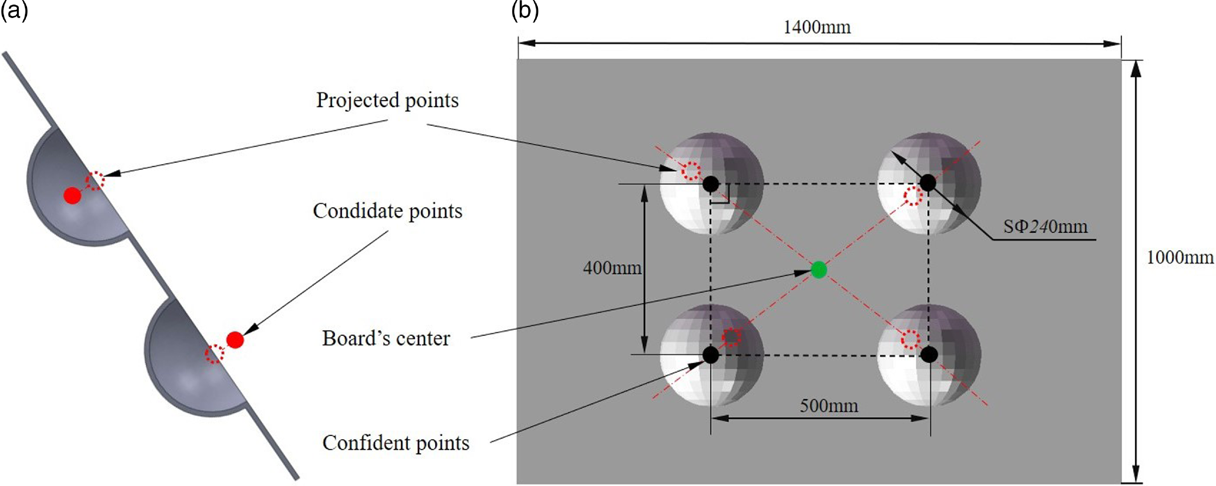
Therefore, it is essential to utilize the calibration board’s available characteristics to optimize the candidate spherical centers in Fig. 4(d). Since the hemispherical surfaces are located on the calibration board’s plane, it is reasonable to project the candidate centers onto the plane, as illustrated in Fig. 5(a). The fitted candidate points are indicated by red solid circles, and the points projected onto the calibration board are represented by dashed circles. Depicted in Fig. 5(b) is the standard geometric arrangement of the four hemispheres, which implies that the spherical centers are equidistant from the calibration board’s center. We determine the center of the calibration board by taking the average of the four projected points. Subsequently, each candidate spherical center is adjusted in the direction of the board’s center until it reaches the actual value. Fig. 5(b) shows the selected calibration board with a green dot representing its center and the black dots indicating updated confidence points. Finally, the black dots
 $\pi ^{c}\left (p_{c,j}^{C} \right )$
 $\pi ^{l}\left (p_{c,j}^{L} \right ), j \in \left \{1,2,3,4 \right \}$
serve as the reference points that we require.
2.3. Registration and optimization
The second stage aims to determine the rigid body transformation
 $T_{L}^{C}$
between the cameras and LiDAR coordinate systems by utilizing the reference points obtained in the previous steps. Since the above procedures rely on single-frame data, it is possible to accumulate
 $N_{acc}$
frames for a single calibration board position. The sets of sphere centers acquired from the point clouds can serve as reference points between the two sensors. The loss function can be established easily by referring to the problem definition described previously:
 \begin{equation} \mathop{\arg \min }\limits _{R,t}\sum _{i=1}^{4 \cdot N_{acc}} \sum _{j=1}^{4}\left \| \pi ^{l}\left (p_{c,j}^{L} \right ) - R \pi ^{c}\left (p_{c,j}^{C} \right ) - t\right \|_{2}^{2} \end{equation}
where
 $R^{T}R=I$
, the rigid body transformation from LiDARs to cameras, denoted as
 $T_{C}^{L}$
, can be described by a rotation matrix
 $R\in \mathbb{R}^{3\times 3}$
and a translation vector
 $t\in \mathbb{R}^{3}$
. The estimation of the transformation matrix between
 $p_{i}^{L}$
and
 $p_{i}^{C}$
is typically achieved using the widely used ICP method. However, the customized calibration board has unique characteristics that enable us to properly sort the sphere centers based on their inclination angles from the origin of the coordinate system, ensuring that the points of
 $p_{i}^{L}$
and
 $p_{i}^{C}$
are appropriately associated. Once the association mentioned above is established, we can determine the optimal values for
 $R$
and
 $t$
via singular value decomposition of the loss function defined in Equation (3). This approach not only obviates the necessity of an initial guess and iterative optimization but also improves the efficiency of the calibration algorithm.
3. Experiments
3.1. Experimental setup
Our proposed algorithm is evaluated both on the simulation and real-world datasets. The simulated sensor suit is built on the Gazebo [Reference Koenig and Howard32] that incorporates sensor models with actual parameters. It consists of simulated 16-beam, 32-beam, 64-beam LiDARs, and a SLC. For the real-world experiments, we conducted experiments in various environments using our mobile platform designed for building quality inspection, which is equipped with an Ouster-64 LiDAR and a Photoneo scanning camera. Table I presents the sensors utilized in our experiment along with their associated parameters.
The sensors’ parameters in the experiments.

3.2. Performance evaluation
To enhance the representation of the calibration algorithm’s accuracy, we compare the acquired extrinsic parameters with the ground truth (GT). The calibration error consists of two parts, rotation error and translation error, which are specifically expressed as follows [Reference Geiger, Moosmann, Car and Schuster20]:
 \begin{equation} \begin{split} & e_{t} = \left \| t - t_{g} \right \|_{2} \\[5pt] & e_{r} = \angle \left ( R^{-1} R_{g} \right ) \\ \end{split} \end{equation}
where
 $t_{g}$
and
 $R_{g}$
are the GT derived from the settings of the sensors in the simulated environment.
 $t_{g}$
is generated by the translation vector
 $\left (t_{x}, t_{y}, t_{z} \right )^{T}$
, while the rotation matrix
 $R_{g}$
is represented as a combination of roll, pitch, and yaw angles (
 $\varphi _{x}, \theta _{y}, \phi _{z}$
).
 $e_{t}$
represents the Euclidean distance between the measured value and GT, while
 $e_{r}$
is the minimum rotation error on the three axes.
3.3. Calibration results on simulated data
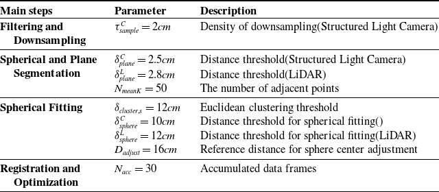
We first verify the LiDAR-frame camera calibration with simulated data. In our experiments, we selected three different resolutions of LiDARs for extrinsic calibration with the SLC. The setting parameters for the main steps of our method, mentioned in the second 2, are shown in Table II.
The setting parameters of our algorithm.
In order to evaluate the effectiveness of our method, we conducted two types of experiments in a simulated environment: 1) single-sensor experiments and 2) synthetic experiments. The former was intended to examine the accuracy of the extracted reference points by changing the location of the calibration board. The second experiment provided a comprehensive evaluation of the algorithm, focusing on the accuracy and robustness of the calibration results. We also compared our method with the algorithm proposed by C. Guindel et al. [Reference Beltran, Guindel, de la Escalera and Garcia29], using ROS implementation. For the fairness of the experiment, the sensors were substituted with SLCs and LiDARs of varying resolutions to assess the applicability of the algorithm. This means that we can compare the performance of different algorithms under the same environment and sensor conditions. In simulation experiments, the GT can be easily obtained from Gazebo.
3.3.1. Single-sensor experiments
In this section, we aim to analyze the precision of the fitted spherical centers for individual sensors by varying the rotation angle of the calibration board. The relative position from LiDAR to SLC is assumed to be (0.1, 0.2, 0.5, 0, 0,0), which corresponds to
 $\left (t_{x}, t_{y}, t_{z} \right )$
and
 $\left (\varphi _{x}, \theta _{y}, \phi _{z} \right )$
, respectively. Additionally, the center of the calibration board is placed at coordinates
 $\left (2.2, 0, 1.8 \right )$
. This location is randomly selected from the overlap, because as long as the camera and LiDAR are within overlap, the results will be similar. The calibration board is tilted along the y-axis by 0 to 45 degrees and rotated along the z-axis from −45 to 45 degrees, with a 5-degree interval between each trial, as shown in Fig. 6.
Fig. 7 shows the Euclidean distance error between the fitted spherical centers and the actual ones at each corresponding angle. The proposed method provides more accurate reference points than the compared algorithm in both the camera and LiDAR’s coordinate systems. It is worth noting that the compared algorithm’s reference points deviate greatly when the rotation angle of the calibration board exceeds 30 degrees. This implies that the proposed algorithm can effectively find reference features regardless of the placement of the calibration board. Importantly, the camera’s data yields a more stable spherical center position than that of LiDAR’s at varying rotation angles. This can be attributed to the fact that the LiDAR’s point cloud on the hemispheres is often sparse, consisting of only a few lines. Furthermore, rotation of the calibration board may cause some lines to become unstable and, in turn, impact the subsequent fitting of spherical centers. Fig. 8 illustrates the translation and rotation errors at each position corresponding to Fig. 7. The trends for both errors are similar, indicating that the proposed method is capable of improving the precision of the fitted spherical centers. This, in turn, leads to more accurate calibration results and significantly enhances the performance of the proposed method.
(a) and (b) represent the rotation of the calibration board around the y-axis and the z-axis.

Euclidean error of the centers in single frame. (a)(c) and (b)(d) demonstrate the error in the LiDARs and camera systems.

The calibration result error at different rotation angles.

3.3.2. Synthetic experiments
Accuracy test
The objective of this experiment is to assess the accuracy of the proposed method relative to a comparative algorithm by testing different positions. We selected SLCs and 64-layer LiDARs as sensors for their ability to generate proper point clouds for the application algorithms. We assessed the effectiveness of our approach across ten distinct relative settings between the two sensors, accounting for both translation and rotations. Table III depicts the settings of each calibration pattern. The initial position where both sensors have a clear view of the calibration board is designated as setting 1. The parameters
 $t_{x},t_{y},t_{z},\varphi, \theta, \phi$
describe the GT values of the SLC with respect to the LiDARs. Settings 2 to 5 and settings 6 to 8 involve only rotation or translation between the two sensors. Complicated scenarios have also been considered in the experiment, such as settings 9 and 10, where the rigid transformations of the two sensors combined both rotations and translations.
Table III presents the quantitative experimental results of our proposed method and the comparative algorithm obtained under ideal conditions without noise. The proposed method proved to be effective across all experimental settings. The translational and rotational errors consistently remained below 1 cm and 0.1 degrees, respectively. Conversely, the comparative algorithm produced unsatisfactory results, displaying significant errors during settings 3 and 9, as well as being unable to complete calibration during setting 5. These experimental results provide evidence of the superiority of our proposed method over the comparative algorithm, even in complex scenarios.
In order to present the error reduction achieved by the proposed algorithm in a more intuitive way, we validated the experimental results by conducting a reprojection experiment. Fig. 9 shows the reprojection outcomes for settings 1, 2, 6, and 9, which represent four different relative pose scenarios: the initial position, pure rotation, pure translation, and rotation plus translation. The white and red point clouds in the figure correspond to the cameras and LiDAR data. The degree of overlap between two point clouds indicates the accuracy of calibration. A higher degree of overlap corresponds to a smaller reprojection error, and therefore higher precision in the calibration results.
The results of setting 1 are displayed in Fig. 9(a)(e). The figures reveal that the proportions and shades of the two colors do not show a noticeable difference, suggesting that performance of both methods is similar to each other. Fig. 9(b)(f) reveals the outcomes of setting 2. The re-projection color of the proposed method is darker than the contrast algorithm, which indicates superior performance. The figures for setting 6, namely Fig. 9(c)(g), illustrate that the calibration board of contrast algorithm is lighter in the lower right corner, indicating a higher level of error compared to the proposed method. Fig. 9(d)(h) demonstrates the results obtained for setting 9. Specifically, the contrast algorithm calibration board shows a significant white area in the upper right corner. However, the proposed method continues to yield satisfactory performance. The re-projection results can fundamentally correspond to the errors in Table III, which provides an intuitive confirmation of the proposed algorithm’s accuracy.
Robustness test
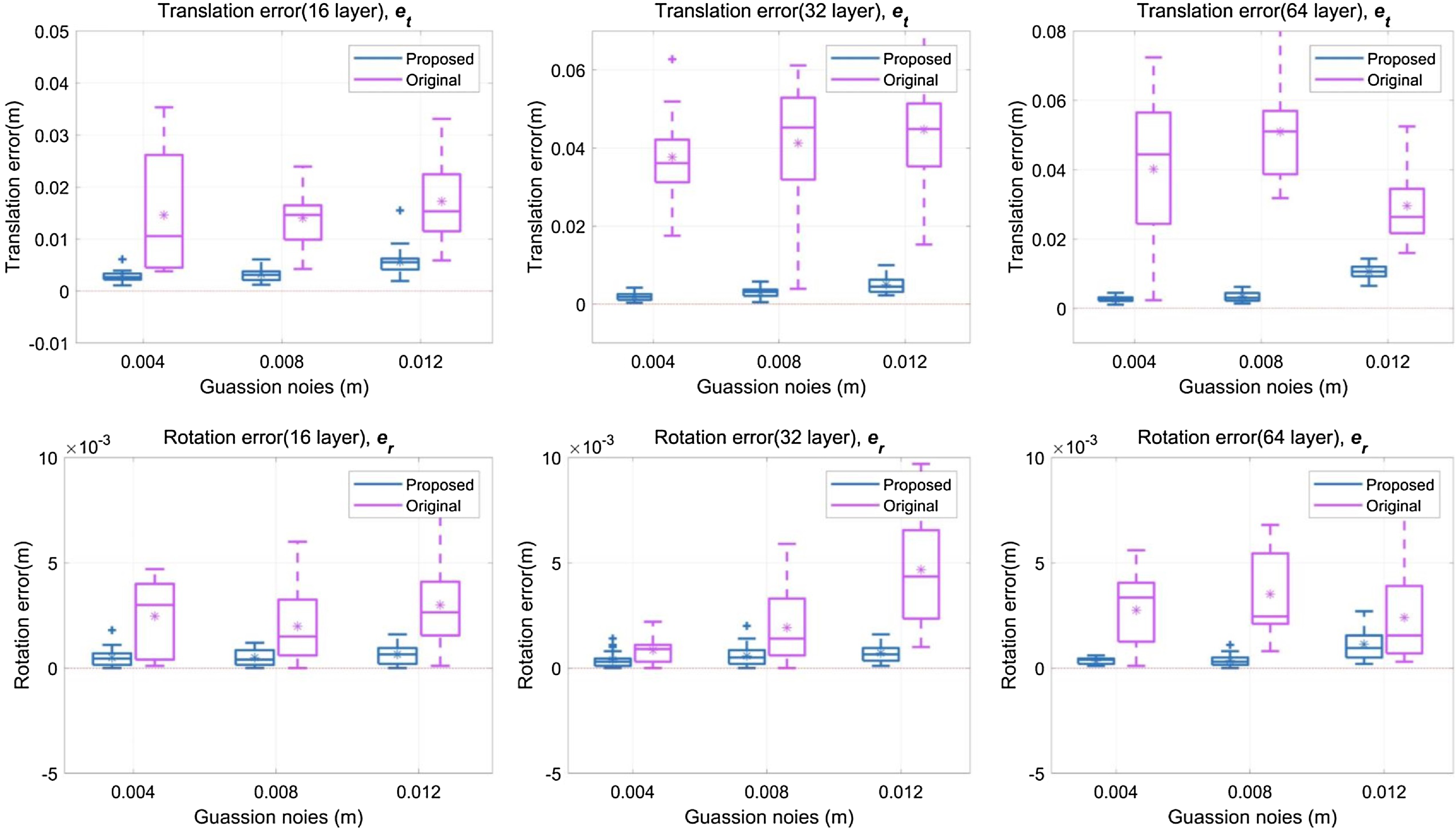
We also evaluate the robustness of our algorithm by introducing Gaussian noise to the sensor data. The installation of these two sensors is situated in more challenging locations, specifically at the 10th setting, where these sensors assume a more complex relative pose. Additionally, we assessed the case of SLC and other different resolution LiDARs, such as VLP-16, HDL-32, and HDL-64. We simulate real-world scenarios by adding Gaussian noise
 $\textit{N}\left (0, \delta _{0}^{2} \right )$
to the sensor measurements.
Each set of experiments was performed 20 times due to the variation in calibration results after adding noise to the sensor information. A statistical analysis of the data is shown in Fig. 10. Our experimental results demonstrate that our proposed method outperforms the comparison method in both translation and rotation errors. Specifically, the results from the proposed method are shown in the blue boxplot of Fig. 10. The mean of this method is closer to the zero baseline, with most of the data clustering around this value. In contrast, the red boxplot displays results from the compared method, with a larger spread of data and a mean further from the zero baseline. These differences indicate that our proposed method is more robust in terms of both translational and rotational errors. As the noise levels increase, the proposed algorithm consistently generates reliable output, while the comparison algorithm exhibits significant deviations.
The sensors’ parameters in the simulation experiments.

The reprojection results of LiDARs to SLC are evaluated under four experimental settings. (a)(b)(c)(d) and (e)(f)(g)(h) are the reprojections from LiDARs to SLC under setting 1, 2, 6, and setting 9, respectively; (a)(b)(c)(d) are the qualitative results of proposed method and (e)(f)(g)(h) are the qualitative results of compared method.

The calibration results of the cameras and LiDARs are presented for various levels of noise, including 0.004m, 0.008m, and 0.012m.
3.4. Calibration results on real-world data
This section tests the proposed method in two real-world scenarios that represent the two most common types of scenes occurring in architectural settings, as shown in Fig. 11. The first scenario (S01) is a narrow-cluttered corner with other objects such as wall, prefabricated components, chairs, and aluminum profile racks, which affect the extraction of board information. The second scenario (S02) is a spacious and well-organized room, with little obstacles or interference. In this study, we conducted practical experiments to compare the proposed method with two other algorithms mentioned in the references [Reference Zhou, Li and Kaess14, Reference Beltran, Guindel, de la Escalera and Garcia29]. These particular algorithms have gained popularity in the open-source community due to their potential to effectively calibrate camera with a LiDAR. To present a comprehensive analysis of our method, we employed a combination of qualitative and quantitative approaches to examine and interpret the calibration results.
The real-world experiment scenarios.

The reprojection of LiDAR points onto the image in S01: our algorithm (green), Zhou et al. (red) and Guindel et al. (yellow).

Fig. 12 and Fig. 13 show the reprojection results of the extrinsic parameters in two different scenes. To enhance the visibility of the reprojection results, we individually projected the results of calibration methods onto each board. The reprojection error of the extrinsic parameters was assessed by examining the overlap between the calibration board’s point cloud and the corresponding image. Notably, our algorithm’s projected point cloud (colored green) demonstrates a closer alignment to the position of the calibration board in comparison to the other two methods. We consider that this is mainly caused by the discontinuity of the point cloud, resulting in the inaccuracy of directly obtained boundary feature points. In contrast, our method indirectly obtains feature points by fitting the point cloud, independent of its discontinuity. In addition, Fig. 12(d)(e)(f) and 13(d)(e)(f) illustrate the point cloud (colored blue) that falls within the calibration board in the reprojection results. A greater proportion of the board point cloud that is occupied by the blue region indicates a more accurate calibration result. The proportion of the blue region in all three methods further emphasizes the superiority of our algorithm over the other two methods.
The reprojection of LiDAR points onto the image in S02: our algorithm (green), Zhou et al. (red) and Guindel et al. (yellow).

For qualitative experiments, as it is unfeasible to determine the exact rigid body transformation between sensors, we adopt the approach developed by Jiao [Reference Jiao, Chen, Wei, Wu and Liu33] to compute a “pseudo-GT.” This is achieved by manually selecting corresponding 3D-3D point pairs and utilizing the ICP algorithm. Table IV displays the errors of the extrinsic parameters obtained by various calibration algorithms based on the computed pseudo-GT. We randomly conducted three sequences of experiments for each scenario illustrated in Fig. 11, using a randomized approach. The results of the six sequences in the table clearly indicate that our algorithm demonstrates more accuracy and robustness in comparison to the other two contrast algorithms. It is worth noting that although Guindel’s method can sometimes yield acceptable results, its outcomes are often unstable and even fail to calibrate. One possible explanation for this is the method’s limited capability to consistently and effectively remove point cloud that does not belong to the calibration board, leading to the inaccurate extraction of edge features.
4. Conclusion
This paper proposes a novel approach with a customized board to calibrate extrinsics between Structured light cameras(SLCs) and LiDARs, which considers fitted sphere centers as feature points. This method can significantly reduce human intervention and utilize the geometric constraints of the calibration board to extract features accurately. The proposed method has been validated through a combination of simulation and real-world experiments, demonstrating performance well with accuracy and robustness.
However, the proposed method is limited to sensors that are capable of providing 3D geometric information and may not be compatible with ordinary cameras. In future research, we can enhance the universality of the calibration algorithm by integrating an optimal number of QR codes onto the calibration board, thereby incorporating other sensors into the calibration framework.
The translation and rotation error in the real-world experiments.

Author contribution
The ideas, methodology, and experimental validation of this work were proposed and implemented by Yangtao Ge and Chen Yao. All the studies and experiments were supervised by Jing Wu. Zirui Wang provided theoretical and technical support in the calibration method and simulation experiments. Wentao Zhang and Haoran Kang raised a series of questions regarding the initial ideas, providing necessary support for further improvement. Huang provided assistance to revise the methodology and conclusion sections, as well as conducting practical experiments with “pseudo-ground truth”. Zhenzhong Jia provided valuable suggestions for improving the paper’s structure and offered suitable experimental scenarios and sensors for practical experiments.
Financial support
This material is based upon work supported by the National Science Foundation of China 62203205, #U1913603, the Guangdong Natural Science Fund-General Programme under grant no. 2021A1515012384 and Technology and Innovation Commission of Shenzhen Municipality under grant no. ZDSYS20200811143601004.
Competing interests
The authors declare no conflicts of interest exist.
Ethical standards
Not applicable.



