Introduction
The congestion of the electromagnetic spectrum and the demand of high data rates devices tend to push the microwave applications to higher frequencies. Recent researches focus on the V-band (40–75 GHz) where various applications are developed like radar, security, medicine, indoor communications, and the 5 G [Reference Ulaganathan, Eibert, Baheti, Jungmaier, Trotta and Eisenberg1–Reference Scott-Hayward and Garcia-Palacios6]. Especially, the 7 GHz unlicensed band around 60 GHz is of great interest for secured broadband communications [Reference Rappaport, Murdock and Gutierrez7–Reference Smulders, Yang and Akkermans9]. Reaching such high frequencies allows achieving wireless data rates of few Gbits/s [Reference Yong and Chong10].
These mass-market applications must be cost-effective, compact, and reproducible while ensuring reliable performance. Within this context, BiCMOS appears as one of the most interesting technology [Reference Urushihara, Takahashi, Kobayashi, Motozuka, Irie, Shirakata and Takinami8, Reference Floyd, Valdes Garcia, Reynolds, Natarajan, Liu, Gaucher, Nakano and Katazama11, Reference Tillack12]. Moreover, it fits with the increasing demand on systems-on-chip that removes the drawbacks of circuits’ interconnections, thanks to a full integration [Reference Urushihara, Takahashi, Kobayashi, Motozuka, Irie, Shirakata and Takinami8, Reference Song, Kang, Tian, Wu, Li, Guo, Ban, Liu, Tang, Liu and Yang13–Reference Liu and Rojas15].
In the telecommunication context, an efficient spectrum discretization is a major challenge; hence, bandpass filtering is a key topic. Filters compatible with systems-on-chip are either planar filters or substrate-integrated waveguide filters. The latter technology exhibits the better quality factor while being much bulkier [Reference Senior, Rahimi and Yoon16]. Concerning planar filters, they can be really compact and easy to implement but they usually exhibit a low-quality factor (<20) [Reference Nan, Mouthaan, Xiong, Shi, Rustagi and Ooi17–Reference Ma, Mou and Yeo24]. To optimize the transmission response while keeping compact size, pseudo-elliptic structures are very interesting. Hence, the presence of transmission zeros in the vicinity of the passband strongly increases the out-of-band rejection while minimizing the filter order, and therefore the insertion loss [Reference Yang, Skafidas and Evans20–Reference Ma, Mou and Yeo24].
This work focuses on ring resonators, a pseudo-elliptic structure introduced in [Reference Wolff25]. This filter topology is usually side-coupled and the associated synthesis is presented in [Reference Mohd Salleh, Prigent, Pigaglio and Crampagne26]. Nevertheless, an easier coupling of the ring filter by direct accesses is presented in [Reference Franc and Prigent27]. The present work presents the full synthesis of the direct coupling ring filter, for an easy and quick design step. Theory section details the ring filter synthesis as well as its technological limitations. An improvement of the synthesis is then proposed to bypass those constraints by the use of capacitive loads along the ring. In 60 GHz filters design section, several second-order 60 GHz ring filters are designed to highlight the synthesis possibilities. They are implemented using the 130 nm BiCMOS technology provided by IHP microelectronics [Reference Tolunay Wipf, Göritz, Wietstruck, Tillack, Mai and Kaynak28]. Finally, Benchmark section presents a benchmark of 60 GHz integrated filters.
Theory
Nominal ring filter synthesis
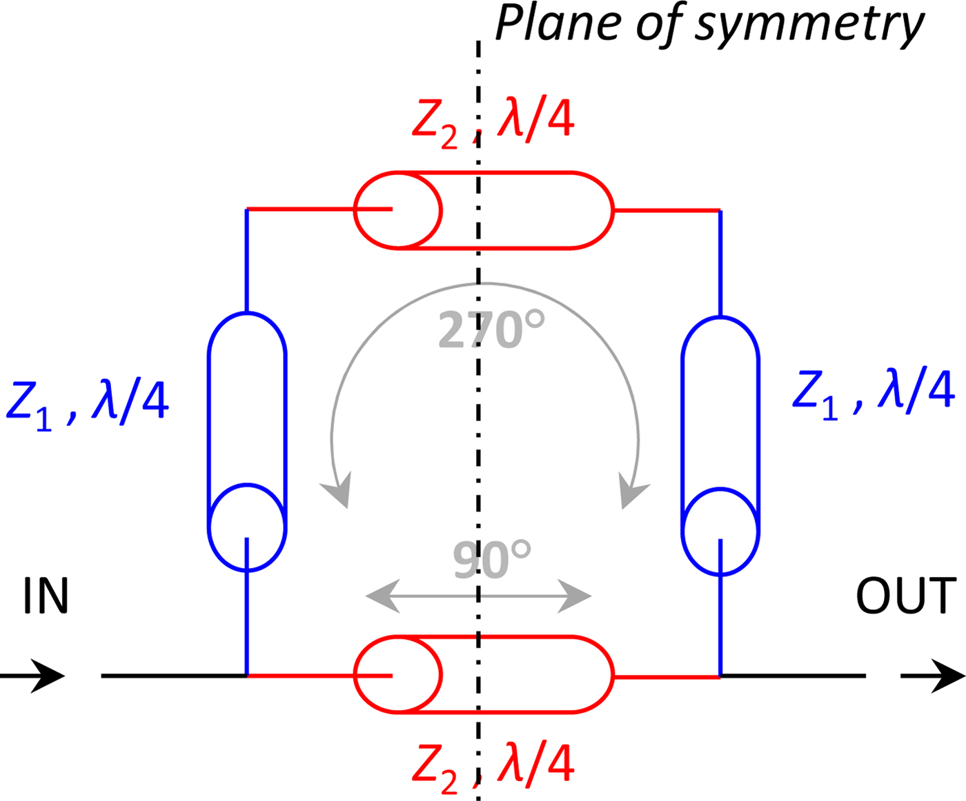
The basic ring resonator is a one wavelength-long cell with direct feeds, as depicted in Fig. 1. This topology exhibits a symmetrical quasi-elliptic frequency response, which is controlled by the characteristic impedance values Z 1 and Z 2 [Reference Franc and Prigent27].
Nominal ring filter schematic.

The proposed synthesis aims at determining the impedance ratio r z = Z 2/Z 1 and the characteristic impedance value Z 1, that fit with the requirement in terms of center frequency (f c), low-frequency transmission zero (f TZ), and in-band return loss (y).
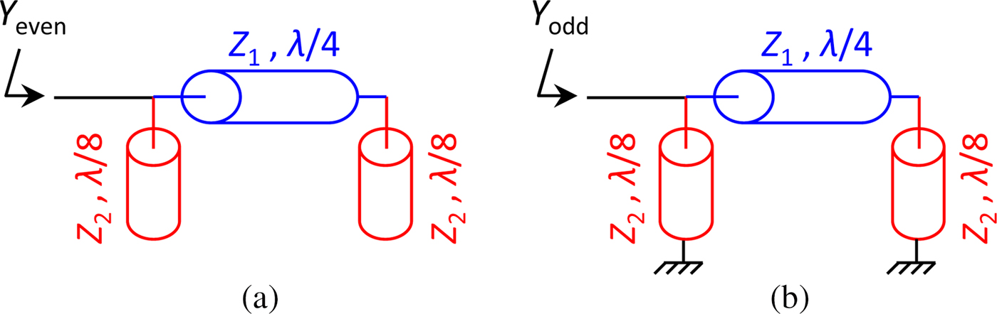
With symmetry consideration, the even- and odd-mode analysis is applied. Based on the equivalent schematics presented in Fig. 2, the even- and odd-mode impedances are, respectively, given by equations (1) and (2).
 $$Y_{even}(\,f) = jY_1 \cdot \left[ {\displaystyle{1 \over {r_z}}\tan \theta _2 + \displaystyle{{\tan \theta _1 + {1 / {r_z \cdot \tan \theta _2}}} \over {1 - {1 / {r_z \cdot \tan \theta _1\tan \theta _2}}}}} \right],$$
 $$Y_{odd}(\,f) = jY_1 \cdot \left[ { - \displaystyle{1 \over {r_z}}\cot \theta _2 + \displaystyle{{\tan \theta _1 - {1 / {r_z \cdot \cot \theta _2}}} \over {1 + {1 / {r_z \cdot \tan \theta _1\cot \theta _2}}}}} \right],$$
where θ 1 and θ 2 are defined by (3) and (4) with f c the center frequency of the filter.
 $$\theta _1(\,f) = \displaystyle{\pi \over 2} \cdot \displaystyle{\,f \over {\,f_c}},$$
 $$\theta _2(\,f) = \displaystyle{\pi \over 4} \cdot \displaystyle{\,f \over {\,f_c}}.$$
Equivalent schematics for (a) the even-mode and (b) the odd-mode impedance calculation.

Thereby, one can calculate the transmission parameter S 21, with Y 0 the normalization admittance (5).
 $$S_{21}(\,f) = \displaystyle{{\Gamma _{even} - \Gamma _{odd}} \over 2} = Y_0 \cdot \displaystyle{{Y_{odd} - Y_{even}} \over {\left( {Y_0 + Y_{even}} \right) \cdot \left( {Y_0 + Y_{odd}} \right)}}.$$
Control of the low transmission zero frequency
At the low transmission zero frequency f TZ (<f c), S 21(f TZ) = 0. This leads to the resolution of Y odd(f TZ) − Y even(f TZ) = 0, with the impedance ratio r z as the unknown variable:
 $$\eqalign{& \displaystyle{{1} \over {r_z}}\cot \theta_{2_{TZ}} + \displaystyle{{1} \over {r_z}}\tan \theta_{2_{TZ}} - \displaystyle{{\tan \theta_{1_{TZ}} - 1/r_z\cot \theta_{2_{TZ}}} \over {1 + 1/r_z\tan \theta_{1_{TZ}}\cot \theta_{2_{TZ}}}} \cr & \quad + \displaystyle{{\tan \theta_{1_{TZ}} + 1/r_z\tan \theta_{2_{TZ}}} \over {1 - 1/r_z\tan \theta_{1_{TZ}}\tan \theta_{2_{TZ}}}} = 0,}$$
where  $\theta _{1_{TZ}} = \theta _1(f_{TZ}) \le {\pi / 2}$ and
 $\theta _{2_{TZ}} = \theta _2(f_{TZ}) \le \pi /4$.
After calculation, a quadratic equation depending on 1/r z appears (7). Its resolution finally leads to (8). Since r z represents an impedance ratio, only the positive solution is considered.
 $$\left( {\displaystyle{1 \over {r_z}}} \right)^2 - \displaystyle{{2\cot \theta _{1_{TZ}}} \over {\tan 2\theta _{2_{TZ}}}} \cdot \displaystyle{1 \over {r_z}} - \left( {1 + 2{\cot} ^2\theta _{1_{TZ}}} \right) = 0,$$
 $$r_z = \left[ {\cot \theta _{1_{TZ}}\left( {\cot 2\theta _{2_{TZ}} + \sqrt {2 + {\tan} ^2\theta _{1_{TZ}} + {\cot} ^22\theta _{2_{TZ}}}} \right)} \right]^{ - 1}.$$
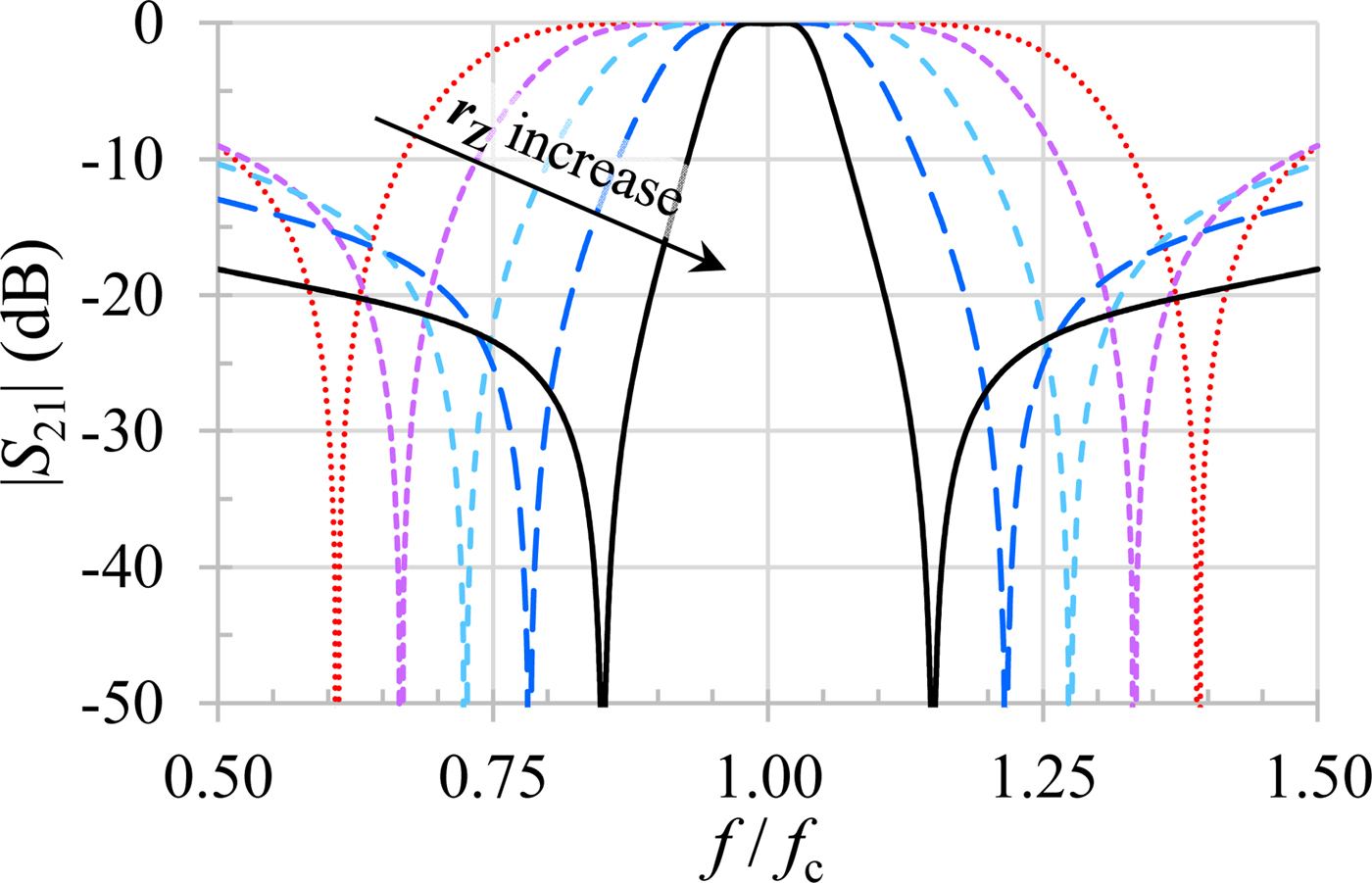
Figure 3 illustrates the electric response of the filter when the ratio r z varies. Only the transmission zero frequencies are affected by an r z change.
Dependence of the electric response with r z = Z 2/Z 1. (r z varies from 0.5 to 0.9, the return loss is set to 20 dB.)

Passband matching control
At the center frequency, the even- and odd-mode admittance expressions are as follow:
 $$Y_{even}\left( {\,f_c} \right) = - jY_1 \cdot \left( {{{r_z - 1} / {r_z}}} \right) = - jY_1 \cdot B,$$
 $$Y_{odd}\left( {\,f_c} \right) = jY_1 \cdot \left( {{{r_z - 1} / {r_z}}} \right) = jY_1 \cdot B,$$
with B defined as B = r z − 1/r z.
Finally, the filter transmission at the center frequency can be written as:
 $$S_{21}\left( {\,f_c} \right) = \displaystyle{{2jY_0Y_1B} \over {Y_0^2 + Y_1^2 B^2}}.$$
By imposing y the return loss, the passband ripple x is such as:
 $$x = \sqrt {1 - {10}^{ - y/10}}. $$
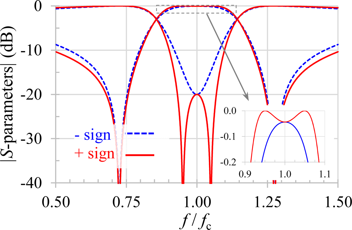
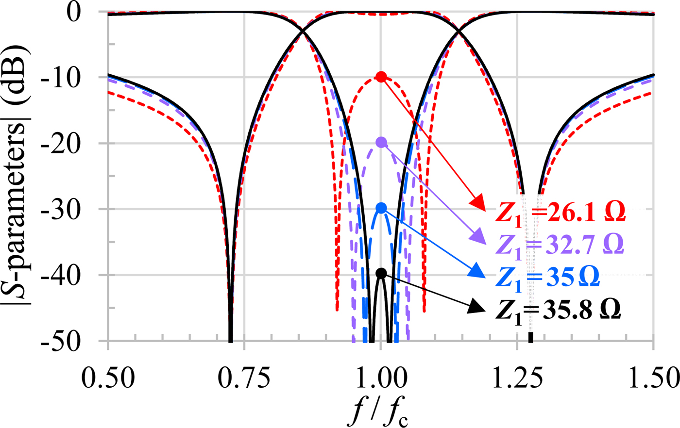
By equaling the modulus of (11) and (12), a quadratic equation appears with Y 1 as unknown variable. Its resolution leads to two solutions for the value of Z 1 (13). The one with the minus sign corresponds to an overcoupled filter response (Fig. 4); therefore, the solution with the plus sign is preferred.
 $$Z_1 = \left[ {\displaystyle{{Y_0} \over {x \cdot \left \vert B \right \vert}} \cdot \left( {\,1 \pm \sqrt {1 - x^2} \,} \right)} \right]^{ - 1}.$$
Electric response with the two Z 1 solutions of equation (13). (The low transmission zero frequency equals 0.725·f c, thus, the impedance ratio r z is 0.7.)

Figure 5 illustrates the control of the in-band return loss with Z 1 for a given low transmission zero frequency (0.725·f c), setting impedance ratio r z to 0.7. The bandwidth (that is only controlled by the transmission zero frequency, i.e. r z) is the same for all the simulations presented in Fig. 5.
Dependence of the electric response with Z 1 value. (The impedance ratio r z is set to 0.7.)

Limitation
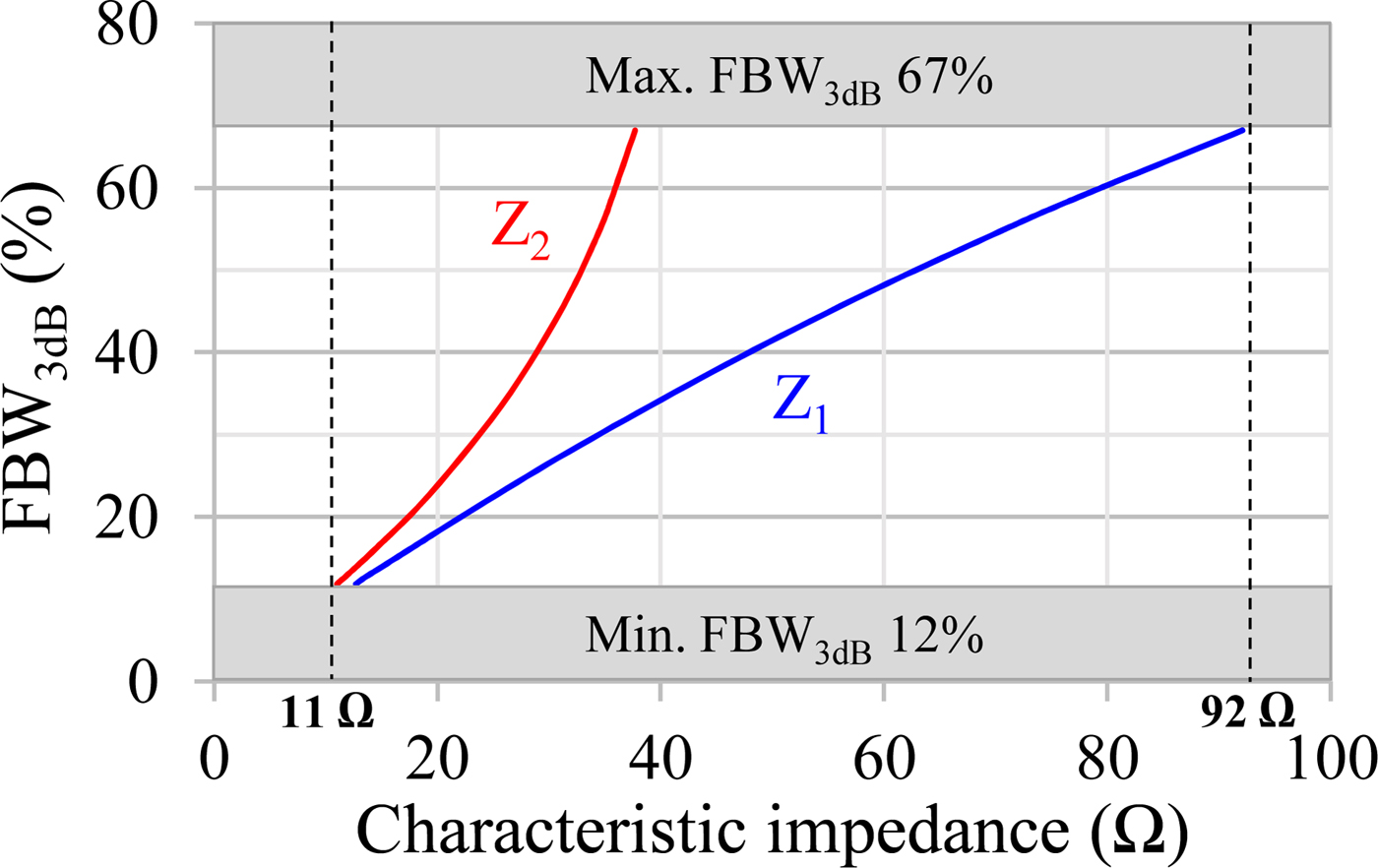
As the impedance ratio directly implies the low transmission zero frequency, it also sets the bandwidth. Thus, for a given technology, the extent of the achievable bandwidth relies only on the characteristic impedance range. For instance, Fig. 6 depicts the achievable bandwidth as a function of the impedance values Z 1 and Z 2. If an impedance range from 11 to 92 Ω is considered, the achievable 3 dB fractional bandwidth (FBW 3dB) varies from 12 to 67%. Thereby, this topology is dedicated to filters with medium to relative wide bandwidth. (Note that the considered impedance range relies on the BiCMOS 130 nm microstrip technology that will be presented later in this paper.)
Achievable 3 dB fractional bandwidth around 60 GHz as a function of the characteristic impedances Z 1 and Z 2.

Capacitive-loaded ring filter synthesis
Bandwidth reduction
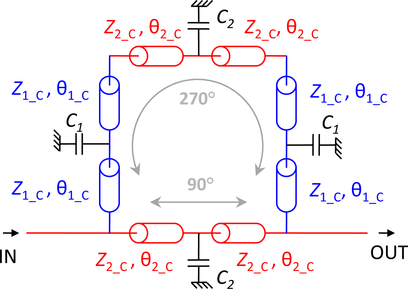
In order to reduce the achievable bandwidth, an evolution of the topology is presented using capacitive loading. Each side of the ring is loaded at its center by a capacitor as shown in Fig. 7.
Capacitive-loaded ring filter schematic.

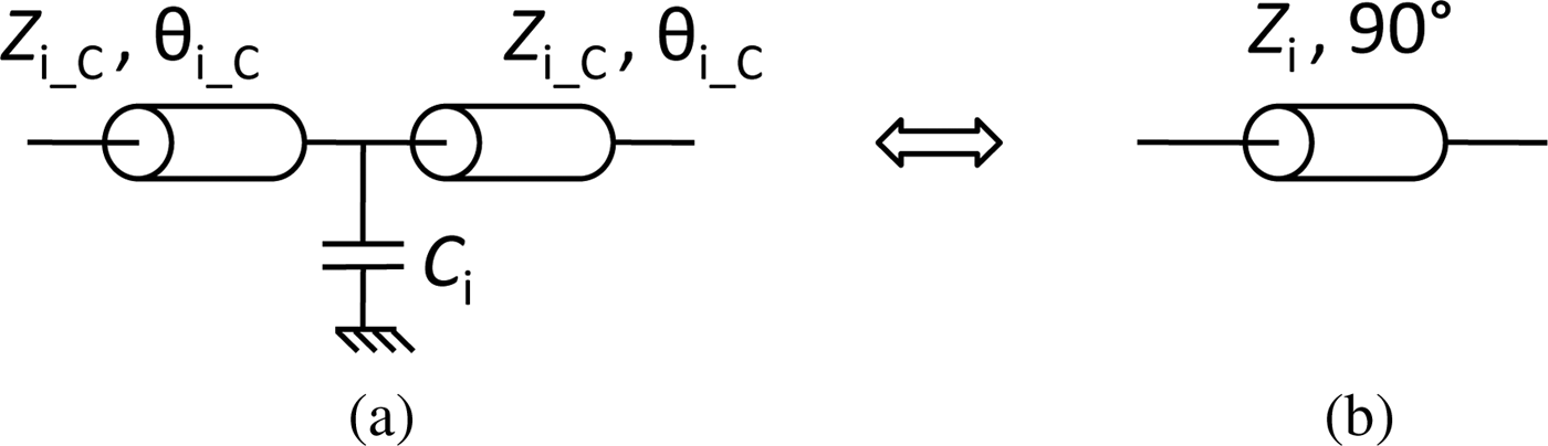
Considering the equivalent networks depicted in Fig. 8, the ABCD matrix of each circuit can be easily determined, Z i_C being the characteristic impedance of the loaded transmission line and θ i_C its electrical length. Comparing the ABCD matrix, equations (14) and (15) appear with ω c = 2π f c.
 $$\cos \left( {2\theta _{i\_C}} \right) - \displaystyle{{Z_{i\_C}C_i\omega _c} \over 2}\sin \left( {2\theta _{i\_C}} \right) = 0,$$
 $$Z_{i\_c}\sin \left( {2\theta _{i\_C}} \right) - \displaystyle{{Z_{i\_C}^2 C_i\omega _c} \over 2}\left[ {1 - \cos \left( {2\theta _{i\_C}} \right)} \right] = Z_i.$$
(a) A capacitive-loaded transmission line and (b) its equivalent conventional transmission line model.

Equation (14) directly gives the required electrical lengths θ i_C (16).
 $$\theta _{i\_C} = \displaystyle{1 \over 2}\arctan \left( {\displaystyle{2 \over {Z_{i\_C}C_i\omega _c}}} \right).$$
The resolution of (15), knowing expression (16), leads to:
 $$Z_{i\_C} = \displaystyle{{Z_i} \over {\sqrt {1 - Z_iC_i\omega _c}}}.$$
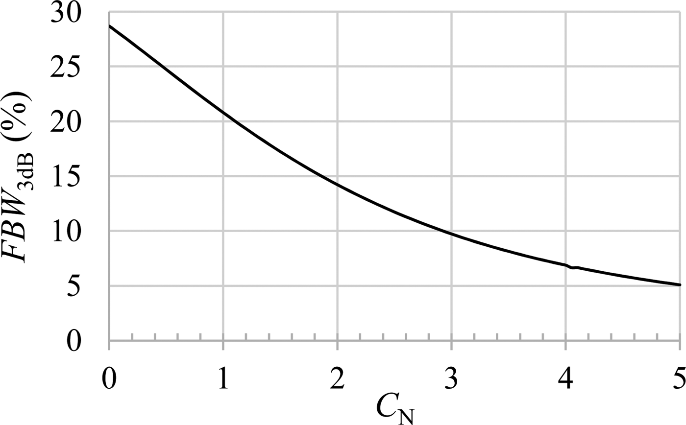
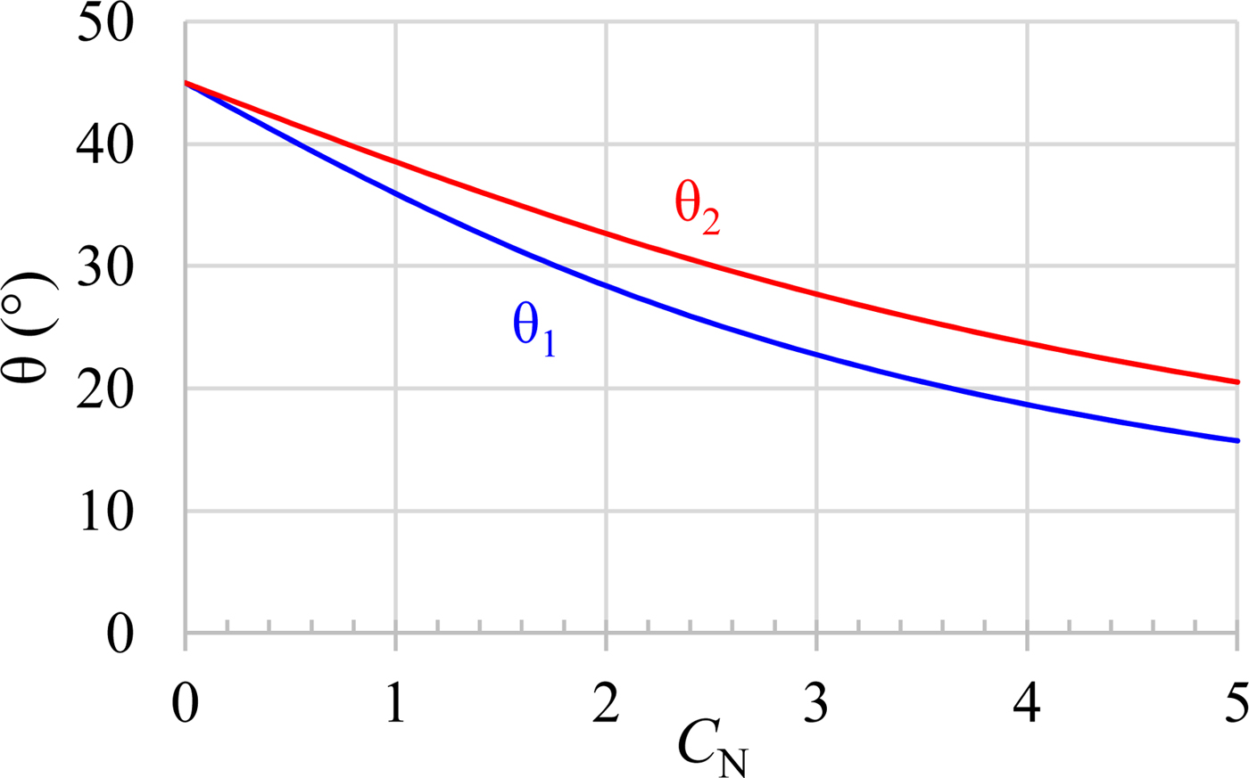
Figures 9 and 10 display the bandwidth and electrical length variations versus normalized capacitor value(C N = Z 0Cω c). The nominal circuit corresponds to C equal to zero; then the capacitive loading is applied with four identical capacitors (C 1 = C 2 = C) while forcing the impedance values to those determined by the nominal synthesis (Z i_C = Z i). As shown in Fig. 9, the higher the capacitor value, the lower the fractional bandwidth. Hence, for a given technology, the capacitive-loaded topology allows reaching lower bandwidths than the nominal one. Moreover, the electrical lengths decrease (see Fig. 10), thus strongly minimizing the size of the filter.
A 3 dB fractional bandwidth as a function of the capacitive loading for C 1 = C 2 = C and given values of Z 1_C and Z 2_C corresponding to the nominal synthesis applied with f TZ = 0.725·f c and y = 20 dB (i.e. Z 1_C = Z 1 = 32.7 Ω and Z 2_C = Z 2 = 23 Ω).

Electrical lengths as a function of the capacitive loading for C 1 = C 2 = C and given values of Z 1_C and Z 2_C corresponding to the nominal synthesis applied with f TZ = 0.725·f c and y = 20 dB.

Design versatility
In terms of implementation, this capacitive-loaded topology offers a high flexibility since the design requires four values {C 1, Z 1_C} and {C 2, Z 2_C}. With these degrees-of-freedom, several filter topologies can be designed to meet the specifications with respect to the technological constraints (available capacitances or characteristic impedances) and the targeted specifications (surface miniaturization or minimization of the insertion loss).
60 GHz filters design
In this section, six second-order filters are presented to validate the previous synthesis with and without the capacitive loads.
Technology
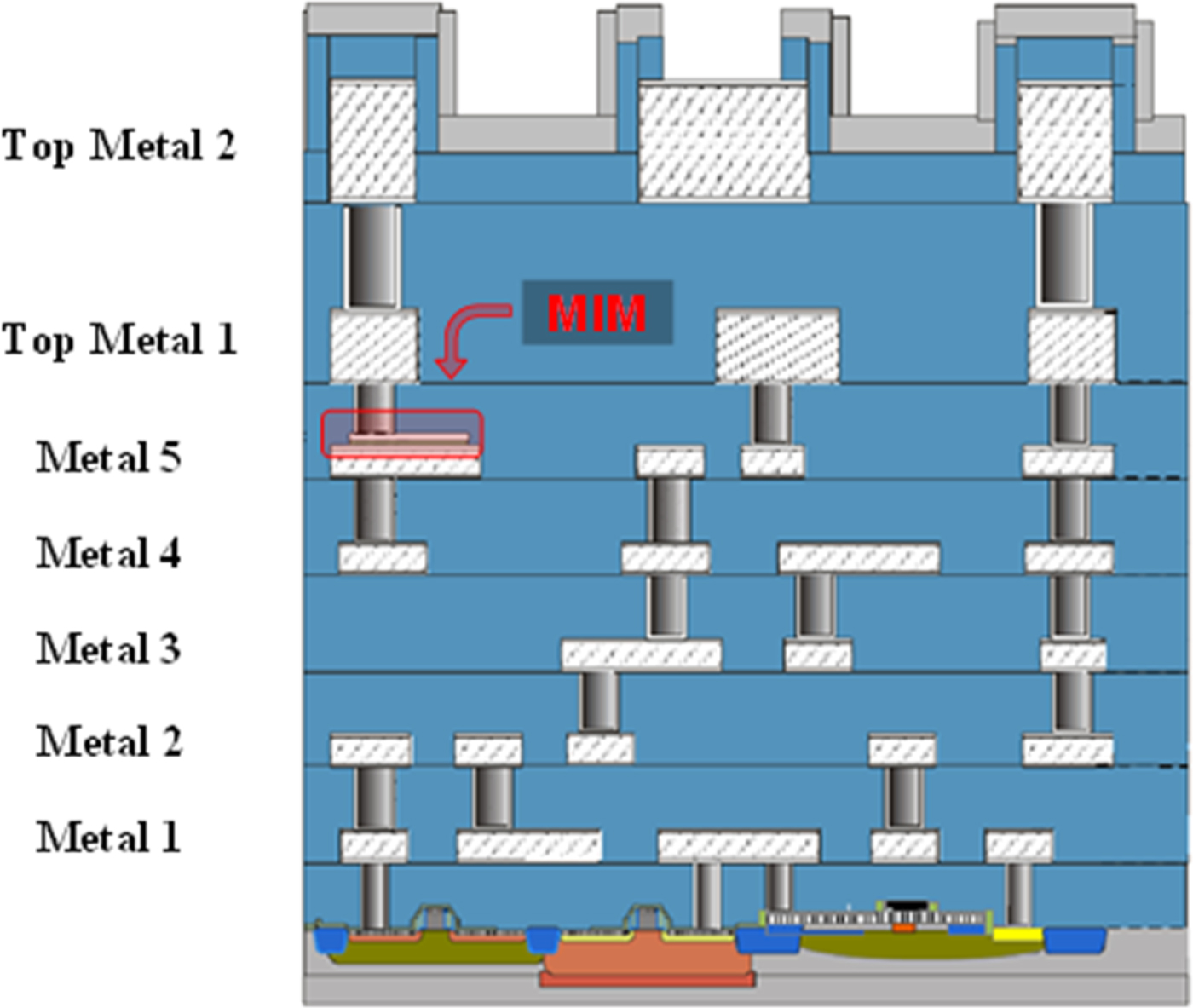
All the realized circuits have been implemented in the IHP's 130 nm SiGe BiCMOS technology presented in Fig. 11. The stack is made of seven aluminum layers including two thick top metals all of them drown in the SiO2. The via holes between layers are made of tungsten and a Si3N4 passivation layer covers the whole die. The process also includes MIM capacitors.
IHP's 130 nm SiGe BiCMOS Back-End-of-Line.

Thin film microstrip transmission lines are used in this work. The lowest layer, metal 1, is used as ground plane and the highest and thickest one, top metal 2 (3 µm-thick), is used as signal line. This allows both decreasing the conductive losses and getting a large impedance range.
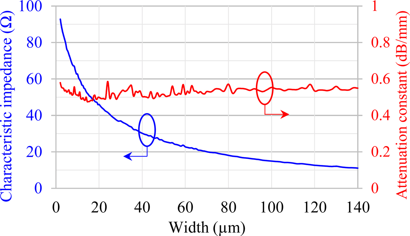
Figure 12 shows the 60 GHz simulated impedance and attenuation constant values versus the transmission-line width. The characteristic impedance range is (11 Ω; 92 Ω). The highest value is set by the top metal 2 width limit (2 µm) given by the design rules. The lowest reachable impedance is 11 Ω for a 140 µm signal width. Larger microstrips might be considered but, for realistic applications, a reasonable shape factor has to be kept between the width and the quarter-wavelength (660 µm at 60 GHz) so that the transitions remain negligible. The simulated attenuation constant hardly depends on the value of the characteristic impedance and remains lower than 0.6 dB/mm at 60 GHz.
A 60-GHz simulated characteristic impedance and attenuation constant for microstrip transmission lines implemented in IHP 130 nm BiCMOS.

Nominal ring filters
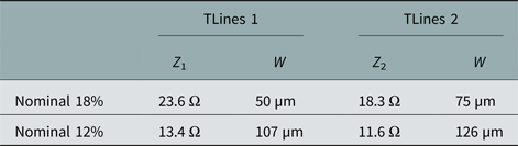
As seen in the theoretical part ( ‘Theory’ section), the lowest impedance sets the narrowest bandwidth. Hence, theoretically, considering the lowest 11 Ω impedance, the FBW 3dB is limited to 12%. In this part, two 60 GHz nominal ring filters (Fig. 1) are proposed with 18 and 12% FBW 3dB. They are composed of quarter-wavelength transmission lines whose characteristic impedances given by the synthesis are summarized in Table 1. Both ring filters are simulated and slightly optimized using the finite-element-method-based software Ansys HFSS™.
Characteristic impedances and associated microstrip widths of the λ/4 transmission lines composing the nominal ring filters

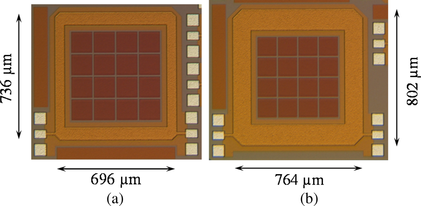
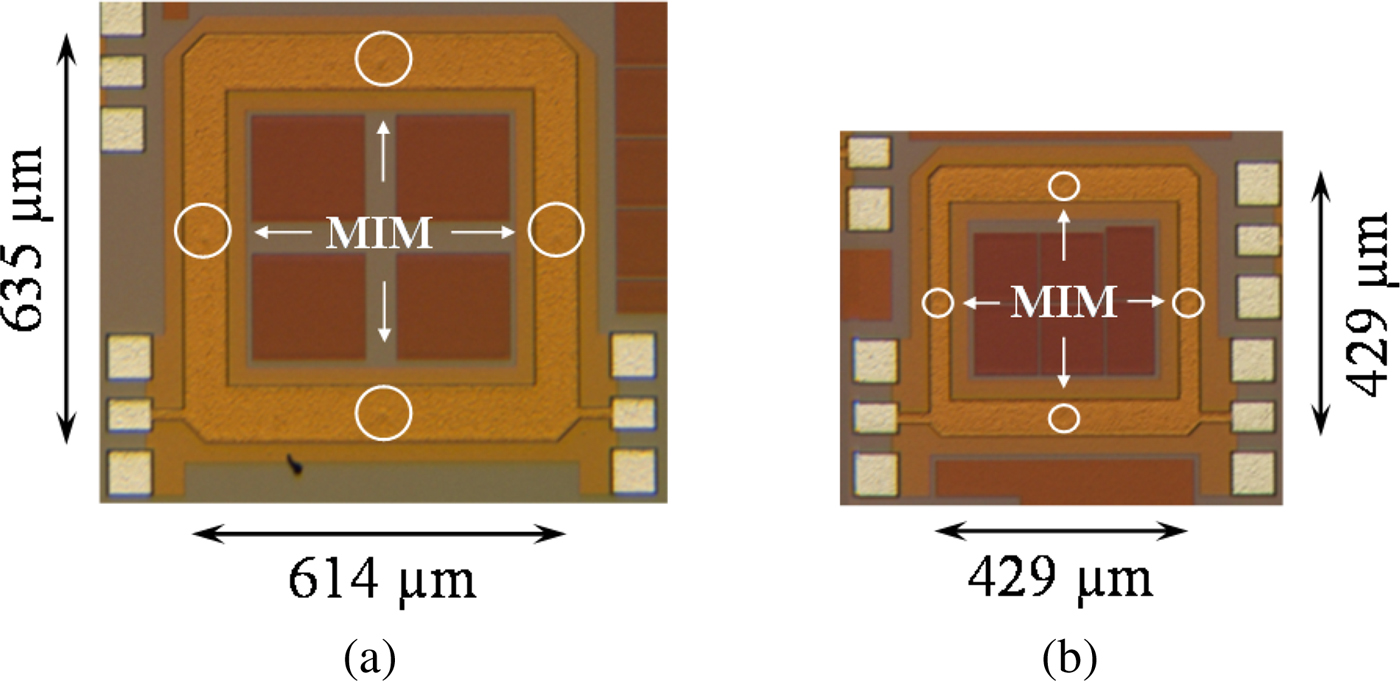
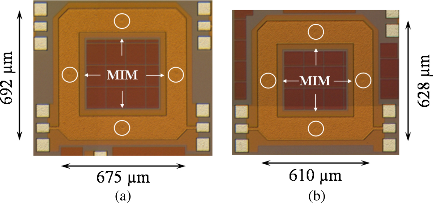
The circuits’ photographs are shown in Fig. 13. Excluding the access lines and RF-pads, the filter footprint is 0.51 mm2 for the 18% FBW 3dB resonator while the 12% FBW 3dB resonator requires a 0.61 mm2 area. (The metal squares in the center of the ring are dummies required to pass the technology density rules.)
Photographs of the nominal ring filters: (a) 18% FBW3dB filter and (b) 12% FBW3dB filter.

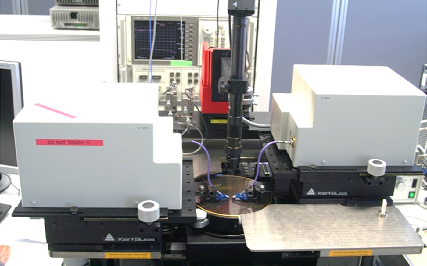
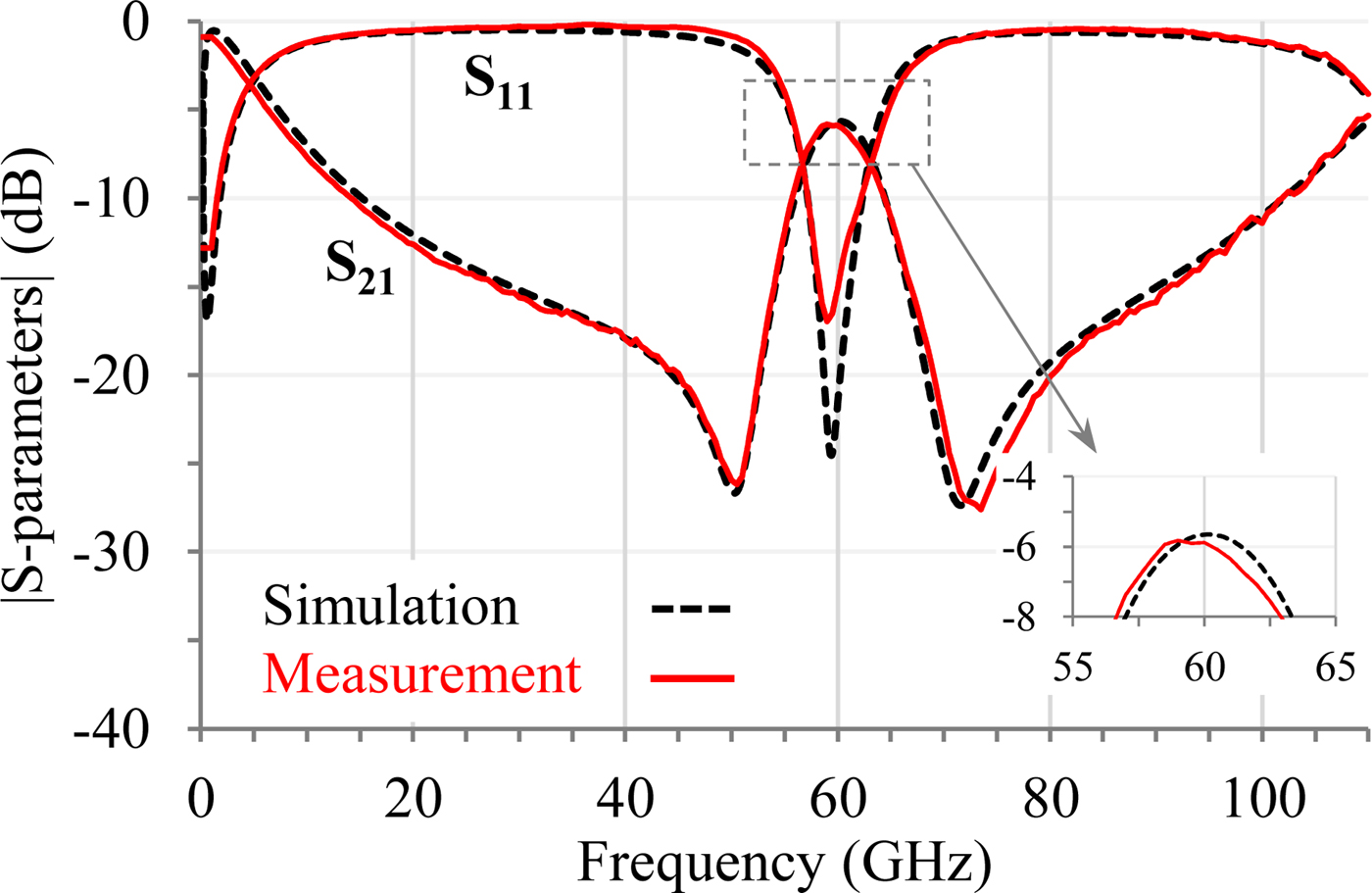
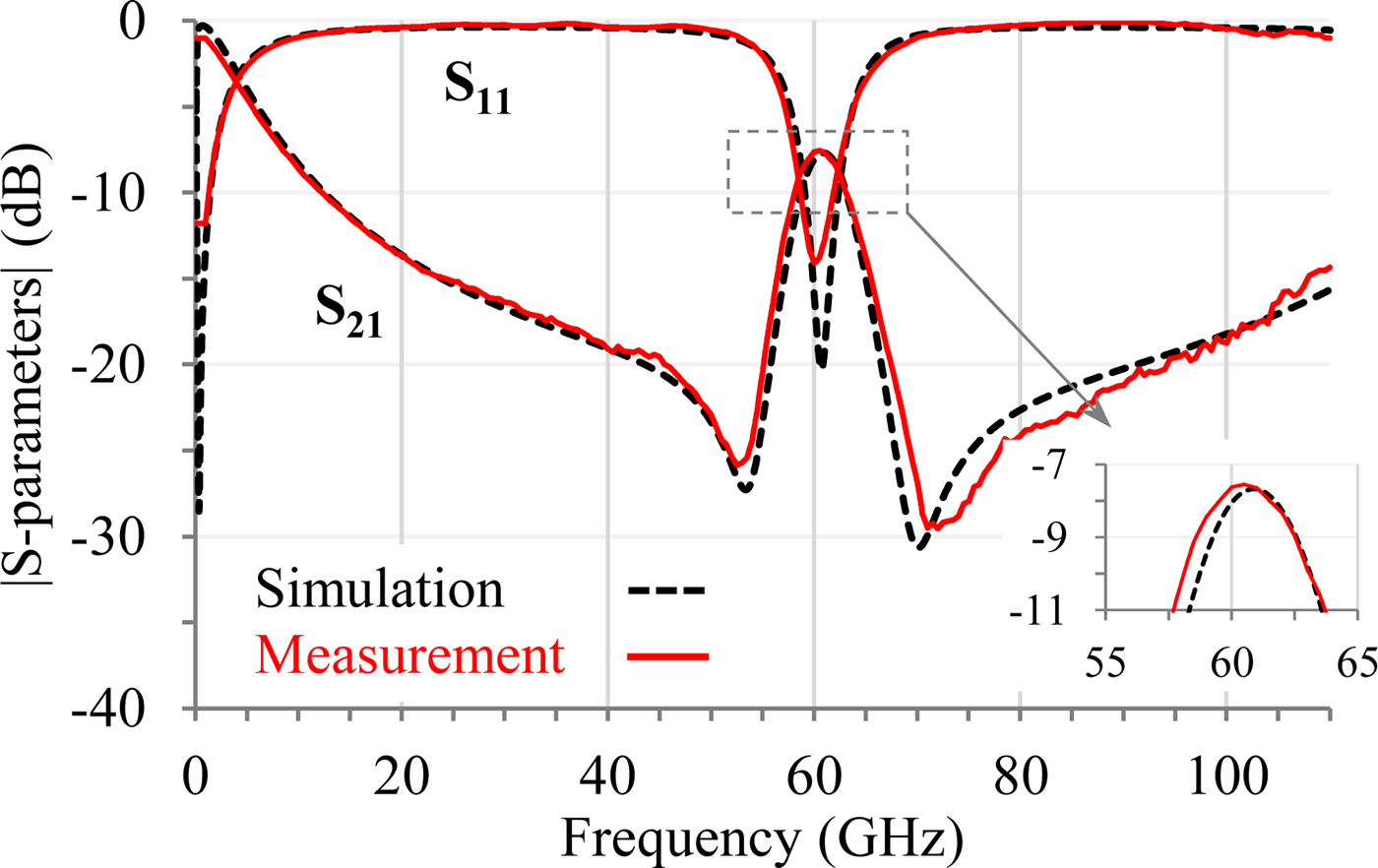
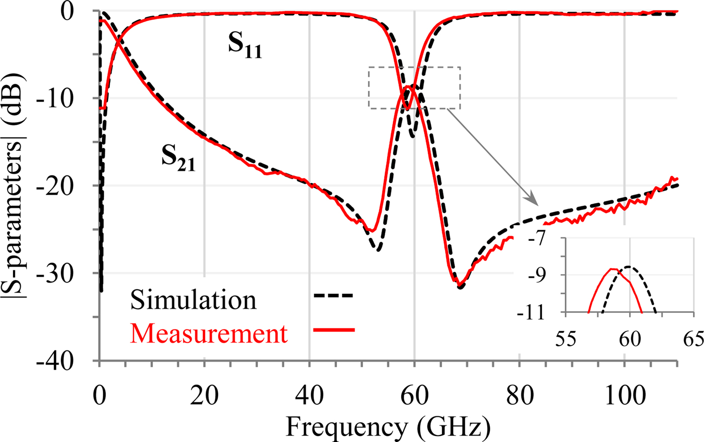
The measurements of these filters were carried out up to 110 GHz with the setup shown in Fig. 14. All measurements, obtained after de-embedding using on-wafer TRL calibration kit [Reference Engen and Hoer29], are in a very good agreement with the simulation results, see Figs 15 and 16.
On-wafer measurement setup.

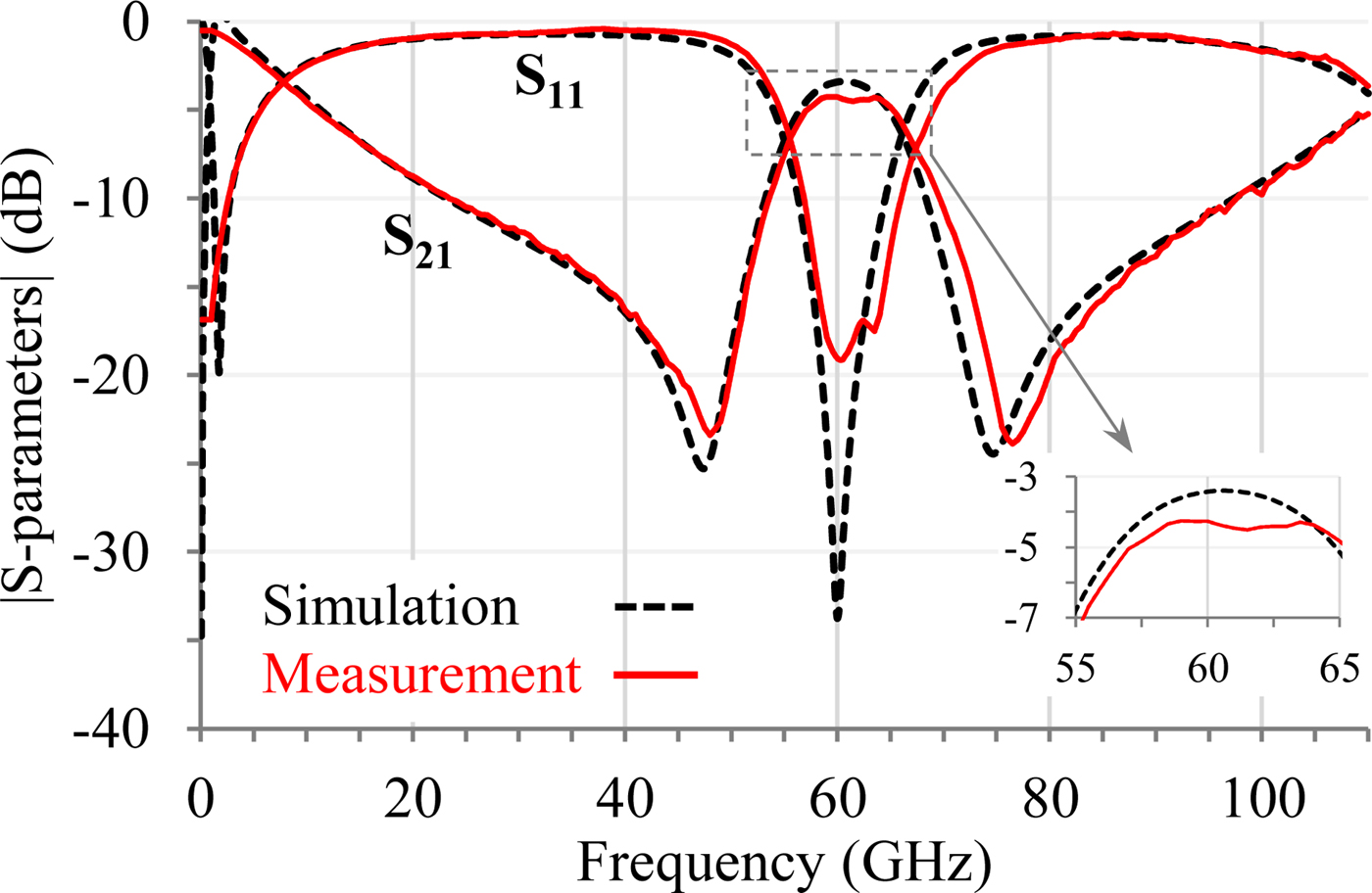
Simulated and measured S-parameters of the 18% FBW3dB nominal ring filter.

Simulated and measured S-parameters of the 12% FBW3dB nominal ring filter.

Figure 15 displays the 18% FBW 3dB nominal ring results. The simulation predicts a 3.4 dB insertion loss, while the measurements exhibit 4.3 dB for a 20.1% FBW 3dB, which is slightly enlarged compared with the expected 18%. The measured center frequency is shifted by 1 GHz to higher frequencies and the matching level is very good (>18 dB).
In Fig. 16, the measurement fits very well with the simulations on the whole frequency band: The measured FBW 3dB is 12.5% compared with the 12% expected by the simulation, and the measured insertion loss is 5.8 dB compared with the simulated 5.7 dB.
The very good agreement between the simulation and the measurement results proves the high reliability of the nominal synthesis and the high level of confidence and accuracy of the design models. Actually, as no modification on the synthesis values has been done (except negligible changes to take the corners electromagnetic effects into account), it is very convenient for designers to use and target filters with given technical specifications.
The main limitation of this nominal synthesis is the very low required impedances for narrow-band filters (see Fig. 12). For instance, the filter with 12% FBW 3dB of Fig. 13(b) requires microstrips as large as 126 µm, i.e. λ/20, which is bulky and not convenient for the design. So, next part will focus on the capacitive-loaded ring filter synthesis that allows the designer to easily reach narrower bandwidths.
Capacitive-loaded ring filters
Using the capacitive-loaded ring filter synthesis presented in Capacitive-loaded ring filter synthesis section, four filters were designed at 60 GHz (schematic Fig. 7 with the same capacitors, i.e. C 1 = C 2 = C). For comparison purposes with the nominal one, two filters were designed to get a 12% FBW 3dB with two different capacitor values. Then, to push the limit of narrow bandwidth, two 8% FBW 3dB filters were designed. They also differ in terms of the used capacitances. All capacitances obtained with the synthesis were implemented with metal–insulator–metal capacitors available in the process.
12% capacitive-loaded ring filter
Two 12% FBW 3dB filters were designed with either capacitances of 88.5 fF or 140 fF. All the electrical properties from the synthesis as well as the physical dimensions are summarized in Table 2. The two ring filters are shown in Fig. 17. The one using 88.5 fF capacitors has a surface area of 0.39 mm2 and the one with 140 fF capacitors requires both thinner and shorter transmission lines and only requests 0.18 mm2.
Photographs of the capacitive-loaded 12% FBW3dB ring filters with (a) 88.5 fF and (b) 140 fF capacitors.

Twelve percent FBW 3dB capacitive-loaded ring filters electrical and geometrical properties at 60 GHz

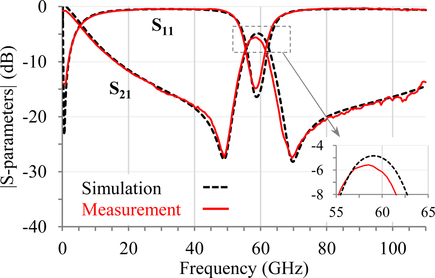
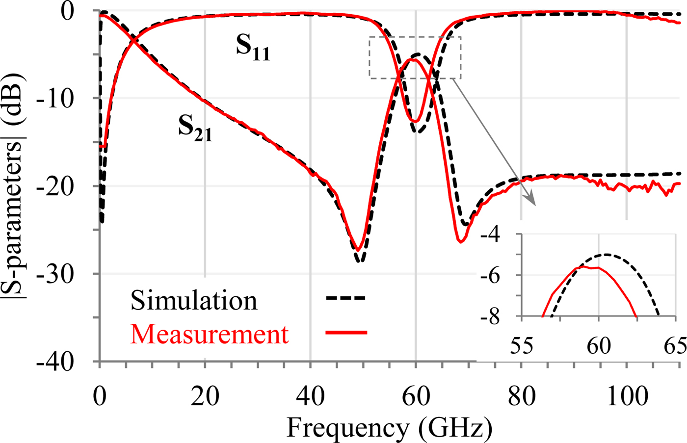
The measurement and the simulation results of these 12% FBW 3dB capacitive-loaded ring filters are shown in Figs 18 and 19. In both cases, the measured center frequency, return loss, and FBW 3dB agree very well with the simulation results. The measured insertion loss is 5.6 dB, whereas the nominal filter exhibits 5.8 dB insertion loss for identical bandwidth.
Simulated and measured S-parameters of the 12% FBW3dB ring filter loaded with 88.5 fF capacitors.

Simulated and measured S-parameters of the 12% FBW3dB ring filter loaded with 140 fF capacitors.

With almost similar electrical performance, the 12% FBW 3dB capacitive-loaded topology is much more compact than the nominal one. Moreover, the higher the capacitance is, the stronger the miniaturization is (up to a factor 3.4 with 140 fF capacitors).
Those results also highlight how efficient the proposed synthesis is. Actually, this double synthesis (with and without capacitors) allows a very high flexibility for the designer. Hence, for a given specification, the designer can choose either to use a nominal topology without capacitors (e.g. if not available in the technology) or to implement capacitive-loaded ring to target a specific miniaturization in adjusting the capacitor values.
Narrow-band capacitive-loaded ring filters
The miniaturization purpose is a great advantage of the capacitive-loaded topology. Nevertheless, another strong benefit is to allow reaching narrow bandwidths that cannot be achieved with the nominal structure.
As previously mentioned, according to the technological limitations in the 130 nm BiCMOS process, the 3 dB bandwidth of the nominal ring filter topology has a lower limit of 12%. To bypass this limitation, 8% FBW 3dB ring filters at 60 GHz are realized with the capacitive loads and associated synthesis. Two filters are implemented with two capacitance values to compare the electrical performance and validate the synthesis in different cases.
All the electrical and dimension characteristics are given in Table 3. The capacitive-loaded ring filter with an 88.5 fF capacitance requires a 0.47 mm2 surface area while the circuit using a 160 fF capacitance has an on-chip area of 0.38 mm2 (Fig. 20). Once again, the measurements and simulations (Figs 21 and 22) are in a very good agreement. For the 88.5 fF loaded ring, the insertion loss reaches 7.7 dB and the return loss 14 dB, whereas the 160 fF loaded ring filter exhibits an 8.7 dB insertion loss and an 11 dB return loss.
Photographs of the capacitive-loaded 8% FBW3dB ring filters with (a) 88.5 fF and (b) 160 fF capacitors.

Simulated and measured S-parameters of the 8% FBW3dB ring filter loaded with 88.5 fF capacitors.

Simulated and measured S-parameters of the 8% FBW3dB ring filter loaded with 160 fF capacitors.

Eight percent FBW 3dB capacitive-loaded ring filters electrical and geometrical properties at 60 GHz

This section is a complete application of the nominal and capacitive-loaded ring filter synthesis. The validation is carried out on moderate-band 60 GHz filters with 3 dB fractional bandwidth of 18, 12, and 8%. It highlights the high flexibility of the topology depending on both the expected size reduction and the technology (e.g. capacitors available or not, which capacitor values).
It is also worth mentioning that the direct synthesis application gives directly good electromagnetic performance (no tuning and no post-simulation are required). Moreover, it also confirms the very good reliability of the BiCMOS process.
Benchmark
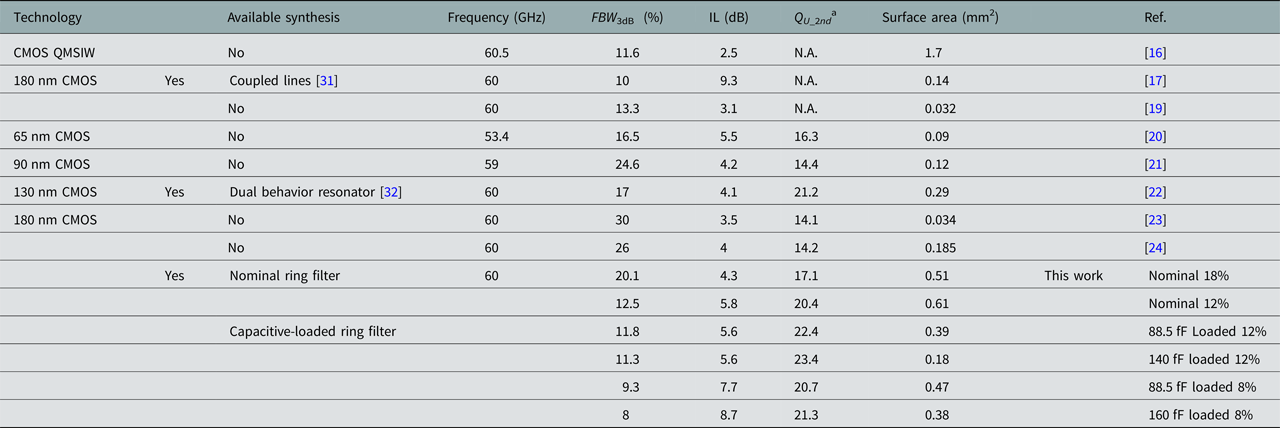
In this section, a benchmark is performed between several 60 GHz bandpass filters implemented in various CMOS technologies, see Table 4. Medium bandwidths are considered and a special attention is given to determine if those filters are fully dimensioned based on a published synthesis. In addition, they are compared in terms of required surface area and electrical performance. To take both the insertion loss and the bandwidth into account, a quality factor calculation is made with the approximation (18), introduced by Cohn in [Reference Cohn30]. Since the g k are the coefficients of the n th order Butterworth polynomial, this approximation is accurate for filters showing a Butterworth response. Hence to fairly compare the filters presented in Table 4, the quality factor is calculated only for pseudo-elliptic second-order filters, i.e. having a good rejection on both sides of the passband. (Those do not present a Butterworth electric response but no accurate approximation exists in this particular case.) For second-order filters, the approximation of (18) becomes (19).
 $$Q_u = 4.343 \cdot \displaystyle{{\sum\limits_{k = 1}^n {g_k}} \over {IL \times FBW_{3dB}}},$$
 $$Q_{u\_2^{nd}} = \displaystyle{{14.8} \over {IL \times FBW_{3dB}}}.$$
Medium band CMOS bandpass filters around 60 GHz

a Q U_2nd is calculated only for second-order pseudo-elliptic responses.
The quarter-mode substrate-integrated waveguide filter in [Reference Senior, Rahimi and Yoon16] shows the lowest loss but also the largest footprint reported in Table 4. The lumped-element-based bandpass filter in [Reference Vanukuru19] displays very interesting electrical performance and is really compact but, without transmission zeros close to the passband, its out-of-band rejection is not sharp enough and reaches only 10 dB at 90 GHz.
Among the quasi-elliptic response, the solutions presented in [Reference Yang, Skafidas and Evans20, Reference Lu, Yeh and Wei21, Reference Chen, Yeh and Chuang23, Reference Ma, Mou and Yeo24] exhibit similar electric performance since their quality factors are between 14.1 and 16.3. They differ in surface area, the filter of [Reference Chen, Yeh and Chuang23] being the most compact with only a 0.034 mm2 footprint. Even if the solution of [Reference Lu, Yeh and Wei21] is based on a thorough analysis reported in [Reference Lei and Wang33], none of those filters is based on a synthesis, i.e. the electrical properties are not directly given by the targeted technical specifications.
Finally, three solutions designed with a full synthesis remain: [Reference Nan, Mouthaan, Xiong, Shi, Rustagi and Ooi17] is based on coupled lines design, [Reference Franc, Pistono, Gloria and Ferrari22] uses dual behavior resonators, and the filters of the present paper. The 60 GHz conventional coupled lines filter of [Reference Nan, Mouthaan, Xiong, Shi, Rustagi and Ooi17] is more compact than the present work, but the associated insertion loss is the highest referenced in this state-of-the-art and it is not pseudo-elliptic so difficult to truly compare with others. In [Reference Franc, Pistono, Gloria and Ferrari22], low losses are measured thanks to both a compact slow-wave structure and copper metal layers. This leads to a good 21.2 quality factor. The present work, implemented with aluminum metal layers, exhibit quality factors ranging from 17.1 to 23.4. As the highest value is obtained for the loaded solution with high capacitances, it also presents the advantage to be quite compact.
Conclusion
The synthesis for direct access ring filter is detailed. The characteristic impedances of the quarter-wavelength transmission lines are fully determined with the targeted electrical response defined with the center frequency, the low-frequency transmission zero, and the return loss level. To decrease the achievable bandwidth, capacitors are added in the filter topology and the synthesis is therefore updated. This evolution leads to a miniaturization and to an important versatility of the synthesis as various degrees-of-freedom can be adjusted by the designer.
Finally, the two syntheses are implemented at millimeter-wave in a 130 nm BiCMOS technology. Two nominal ring filters are measured at 60 GHz: the first exhibits an 18% FBW 3dB for a 4.3 dB insertion loss and the second has 5.8 dB of insertion loss for a 12% FBW 3dB. To highlight the flexibility of the capacitive-loaded filter synthesis, two 12% FBW 3dB filters with different capacitances are characterized. They exhibit very similar electrical responses as the nominal topology but are much more compact (up to a factor 3.4). Finally, to push the limit of low bandwidth, two capacitively loaded filters with different capacitor values are implemented to reach an 8% FBW 3dB.
Acknowledgement
The authors would like to thank Christian Wipf and Barbaros Cetindogan, IHP (Germany), for their assistance and the on-wafer measurements.
 Pedro Rynkiewicz received the M.Sc. degree in electrical and signal processing engineering from ENSEEIHT, Toulouse, France in 2014. He is currently pursuing a Ph.D. degree in electronics at the Laplace, Toulouse University, Toulouse, France. He studied solutions for tunable cavity filters and tunable manifold with the CNES, Toulouse, France. Now, his research focuses on planar filter tunability. His main problematic is to realize filters which are tunable in both frequency and bandwidth.
 Anne-Laure Franc received the engineer and M.Sc. degrees from the Cergy-Pontoise University, Paris, France, in 2008 and the Ph.D. degree from the Grenoble University, France, in 2011. In 2012, she had a postdoctoral position with the Darmstadt University, Germany and she held a temporary lecturer and research assistant position in the Grenoble-Alpes University, Grenoble, France in 2013. Since September 2013, she has been an assistant professor with the University of Toulouse, France. Her research interests focus on tunable microwave components.
 Dr. Fabio Coccetti has a MS degree in Electrical Engineering from the University of Perugia, Perugia, Italy and the PhD title in High Frequency Engineering at the Lehrstuhl für Hochfrequenztechnik at the Technische Universität München (TUM) in Munich Germany, in 1999 and 2004 respectively. In 2000 he has been visiting scientist, at the University of Michigan. From 2004 to 2016 he worked as associate research scientist at the Laboratoire d’Analyse et d’Architectures des Systèmes at the Centre National de la Recherche Scientifique (LAAS-CNRS) in Toulouse, France. From 2008 to 2016 he joined the company Elemca SAS, as RF-Microsystems devices and circuits expert and R&D project manager. In 2014 Dr. Coccetti co-founded RF-Microtech France SAS, a company based in Toulouse of which he has been general manager from May 2016 to February 2018. Starting from March 2018 he is with the Institute of Technology Antoine de Saint Exupéry in Toulouse France. His competences range from design and optimization, to reliability analysis of frequency agile circuits (MEMS, ferroelectric, …) for microwave and millimetre devices for wireless communication and sensing.
 Matthias Wietstruck received his Diploma in Microsystems Technology in 2009. Since 2010 he is with IHP Microelectronics, Germany. Since 2015 he is leading the group “Heterointegration of Devices and Technologies”. His research interest is in the field of Through-Silicon Vias for monolithic and heterogeneous integration, interposer technologies for mm-wave packaging applications and temporary/permanent wafer bonding.
 Christian Wipf joined the Technology Department of IHP in 2005 and has received his M.Sc. in Electrical Engineering from the University of Technology, Cottbus, Germany, in 2008. He is working in the field of characterization of electronic devices and circuits up to and above 100 GHz within the Technology Department. Furthermore he is designing high voltage control circuitries for MEMS matrix applications.
 Selin Tolunay Wipf received her B.S degree from the Electronics Engineering program of Sabanci University, Istanbul, Turkey in 2010 and her M.S degree from the Electrical and Electronics Engineering Department of Bogazici University, Istanbul, Turkey in 2012. She joined IHP in 2012 and has been working on the RF optimizations of the MEMS devices for the mm-wave applications. Since 2015, she is a member of the ‘Heterointegration of Devices and Technologies' group of IHP with a focus on the RF design, optimization and characterization of the RF-MEMS switches above 100 GHz applications.
 Dr. -Ing Mehmet Kaynak received his B.S degree from Electronics and Communication Engineering Department of Istanbul Technical University (ITU) in 2004, took the M.S degree from Microelectronic program of Sabanci University, Istanbul, Turkey in 2006 and received the PhD degree from Technical University of Berlin, Berlin Germany in 2014. He joined the technology group of IHP Microelectronics, Frankfurt (Oder), Germany in 2008. From 2008 to 2015, he has led the MEMS development at IHP. Since 2015, he is the department head of Technology at IHP. Dr. Kaynak is being affiliated as Adjunct Professor at Sabanci University, Turkey.
 Gaetan Prigent was born on december 2, 1973 in Lannion, France. He received his Ph.D. degree in electronic from the University of Brest, France, in 2002. He was with the Laboratory for Electronics and Telecommunication Systems (LEST), Brest, France until 2004. Since 2004, he has been with the Electronic Laboratory, Institut National Polytechnique de Toulouse (INPT), Toulouse, France. In 2009, he joined the Laboratory for Plasma and Energy Conversion (LAPLACE). In 2011, he has obtained the peer accreditation to supervise research. In 2018, he joined the LAAS-CNRS laboratory, University of Toulouse, France. He is currently an Associate Professor of electronics with the National Polytechnique Institute of Toulouse (INPT), France. He is the head of the 3EA (Electronics, Electrical Energy and Automatics) department at the ENSEEIHT engineering school, Toulouse, France. His research principally concerns the design of passive microwave devices, especially planar filters for millimeter- and submillimeter-wave applications beyond 100-GHz He is working toward the design of MEMs-based tunable circuits and systems integrated is silicon-based technologies (Si-BCB, Si membranes, SOI, BiCMOS, SiGe). His research activities also concern the development of novel filter topologies and associate synthesis.